DoorBird D11 Series Installation Manual
Ip video door station
Hide thumbs
Also See for D11 Series:
- Installation manual (36 pages) ,
- Manual (10 pages) ,
- Connection manual (6 pages)
Table of Contents
Advertisement
Quick Links
Advertisement
Table of Contents

Related Manuals for DoorBird D11 Series


Summary of Contents for DoorBird D11 Series
- Page 1 Page 2-19 Installation Manual IP Video Door Station D11x Series Seite 20-37 Installationsanleitung IP Video Türstation D11x Serie Page 38-54 Manuel d‘installation Interphone vidéo IP Série D11x Páginas 55-71 Manual de instalación Videoportero IP Serie D11x D11x VERSION 2.3, MIN. HW 2.0...
- Page 2 You can always find the most up-to-date version of the shocks. installation manual on www.doorbird.com/support To make things easier we use the term “device” for • Devices with 110-240 V connection: The device the product “IP Video Door Station D11x series”...
- Page 3 as inside a refrigerated area or in front of an air conditioner. WARNING ̵ Places subject to steam or smoke (e.g. near • Before turning on power, make sure wires are heating or cooking surfaces). not crossed or shorted. If not, fire or electric ̵...
- Page 4 • On devices with intercom or built-in speaker found to comply with the limits for a Class B or built-in microphone or signal transmission digital device, pursuant to part 15 of the FCC functions, keep the wires more than 30 cm Rules.
- Page 5 Transportation When transporting the device, use the original NOTICE packaging or equivalent to prevent damage to the device. Warranty Information For information about the device warranty, see www.doorbird.com/warranty...
- Page 6 COMPONENTS* 1x Main Electrical Unit 1x Back-housing with 1x Installation manual 1x Quickstart guide with call button(s) wall-mounting bracket with Digital Passport and front panel 1x Drilling template 1x Waterproof A4 laser 1x Power supply unit (mains adapter) printer paper for labelling with up to four country-specific adapters name plates 1x RJ45 Adapter...
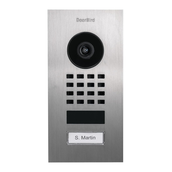
- Page 7 DEVICE WITH 2 CALL BUTTONS Front Inside WIFI 1) Front panel 11) Diagnostic-LED 2) HDTV Video Lights up a few seconds after 3) Security screws connecting the device to power 4) Light Sensor 12) Main Electrical Unit For night-vision mode 13) Screw connection terminal 5) Bluetooth transceiver 14) Gasket...
-
Page 8: Installation
The flush-mounted model may differ optically. VIDEOS Need help with the installation? Be sure to watch our installation videos which can be found on http://www.doorbird.com/support Each individual step of the installation is clearly documented in the videos. INSTALLATION All the steps below should be carried out carefully by a competent adult, taking into consideration any applicable safety regulations. - Page 9 DISMANTLING THE EXISTING SWITCHING OFF POWER DOORBELL Switch off the power to all wires leading to Should there already be a doorbell or door station on the assembly location, i.e. the door chime, the exterior wall of the house, please remove it. electric door opener, power supply unit for the video door station etc.
-
Page 10: Disassembling The Front Panel
Important note for cavity mounting (e.g. in pedestals and mailboxes): To protect the electronic units, please ensure that the technical components are protected against dripping and running water caused by condensate or entering the mounting space through openings. To protect the electronic units, ensure that the mounting space inside is not accumulating water. Sufficient air circulation must be ensured, as well as unobstructed drainage of water at the base of the installation. - Page 11 D1101V D1102V D1101KH Pull the front panel with attached Main Electrical Pull the front panel with attached Main Electrical Pull down the front Unit out of the mounting Unit out of the mounting housing (backbox). panel. housing (backbox). 4.2 MOUNTING Lead all cables and wires you want to connect to the device through the mounting housing.
-
Page 12: Network Connection Options
Install a network cable (which is plugged into a network switch / router “DoorBird 2-Wire Ethernet PoE Converter with Internet access) from the inside of your building to the assembly A1071”, sold separately. It allows you to location. -
Page 13: Connecting The Device
, we recommend to use a PoE-Switch with PoE Standard Injector (e.g. DoorBird Gigabit PoE Injector A1091), use a CAT.5 cable or IEEE 802.3af Mode A or an appropriate higher in accordance with the PoE standard IEEE 802.3af Mode A. - Page 14 COM 1 CB 2 Max 24V Max 0V 15VDC 0 A (NO) LAN/POE CB 1 R1 R1 E1 E1 V- V+ Port Description LAN/POE The device does not have an integrated standarized RJ45 socket to ensure ... • that the device rests as flat as possible on the wall. •...
- Page 15 You can configure the default state of the relay (open/close) via the DoorBird App. These ports can be used to connect e.g. an electric door opener. The device does not supply power to the connected device.
-
Page 16: Activate The Device
ASSEMBLE THE DEVICE TO THE MOUNTNG HOUSING (BACKBOX) Assemble the front panel with the attached Main Eletrical Unit carefully using the orange (Torx+Pin) screw driver provided. D1101V D1102V D1101KH Turn the safety screws clockwise until they are firmly tightened. Tighten the safety screws by hand only (less than 5 newton meter [Nm]), otherwise the Main Eletrical N OT IC E Unit housing may be damaged. -
Page 17: Downloading And Installing The App
For information, terms and If you use WiFi for connecting the device to your conditions see www.doorbird.com/api Internet Router, first go to the DoorBird App > ”WiFi Setup“ and follow the instructions. DOORBIRD CONNECT If you have finished the WiFi setup or have connected... - Page 18 Stainless Steel Only high-quality stainless steel is used for all available DoorBird door stations. However, high-quality stainless steel can also rust, as approx. 70 % of stainless steel is made of iron. Rust resistance is only achieved by a protective layer (also called passive layer), which covers the iron like a skin.
-
Page 19: Troubleshooting
(loose contact). If the problem still exists, please check if your PoE-Switch / PoE Injector supports the PoE Standard IEEE 802.3af Mode A, see also www.doorbird.com/poe If the device is to be supplied with power by a DIN-rail power supply, switch on the DIN-rail... -
Page 20: Legal Notes
Since the products and software of General remarks Bird Home Automation GmbH are not explicitly customer-specific 1. DoorBird is a registered trademark of Bird Home Automation products, a customer cannot deny an automatic update if the GmbH.
Need help?
Do you have a question about the D11 Series and is the answer not in the manual?
Questions and answers