Table of Contents
Advertisement
Quick Links
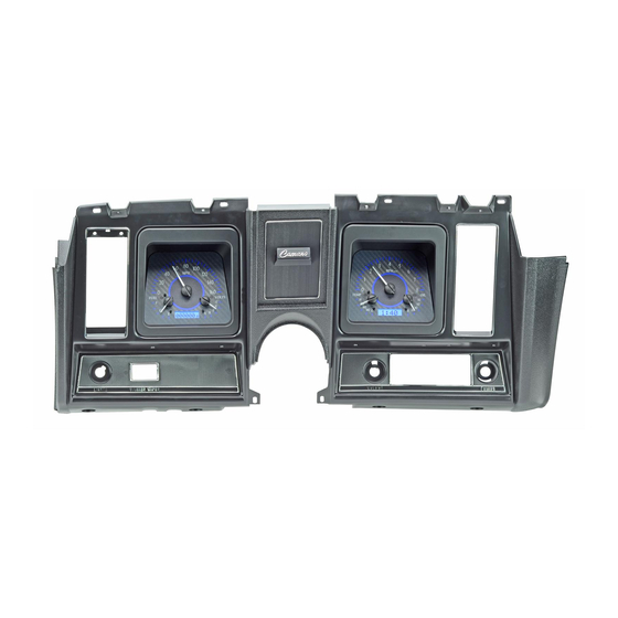
Your new VHX-69C-CAM kit will include:
VHX Displays
(shown with protective film)
Two CAT5 Cables
(To connect Displays to
Control Box)
Installation
1. You may be able to access all of the fasteners with the dash carrier installed, removing the entire
assembly may not be necessary. First, remove the clear lenses from the front. Next, remove the
original gauge internals; they are held into the housing with nuts from the backside. The
discarded pieces should match the photo below:
VHX-69C-CAM
Dakota Digital VHX Instrument Installation
For '69 Chevy Camaro systems
Foam Tape
10-32x1" Mounting Screws w/
nylon washers
10-32x1.5" Mounting Screws
w/ nylon shoulder washers
Installation Manuals
Control Box
Universal Sensor
Pack
Manual # 650318
Advertisement
Table of Contents

Related Manuals for Dakota Digital VHX-69C-CAM


Summary of Contents for Dakota Digital VHX-69C-CAM
- Page 1 VHX-69C-CAM Dakota Digital VHX Instrument Installation For ‘69 Chevy Camaro systems Your new VHX-69C-CAM kit will include: Installation Manuals VHX Displays (shown with protective film) Control Box Universal Sensor Pack Foam Tape 10-32x1” Mounting Screws w/ nylon washers Two CAT5 Cables 10-32x1.5”...
- Page 2 2. Once the original gauge internals have been removed, there are two reflectors (one on each side) inside the housing that need to be removed for clearance of the new VHX gauges (see photo). 3. Now, remove the light bulbs and indicator light panels. Since these functions are built into the VHX system, you can rewire the indicator wires to the control box to retain the desired indicators.
- Page 3 5. Begin with the speedometer installation first; located in the left side opening in the factory dash. Cut three pieces of the supplied foam tape, 2” long. Install foam strips on the top and sides of each opening about ½” down from the face of the housing.
- Page 4 WRONG!!!! Cable will get pinched by the pull block Bezel flush with housing once fully seated in housing and cable properly routed 8. Using the two provided 10-32 x 1.5” screws and nylon shoulder washers, secure the speedometer assembly to the housing. Start the screws into the back of the factory housing and into the pull-block on the back of the gauge assembly.
- Page 5 Mounting screws Cable routed through indicator light opening 10. Both cables should be routed through the stock indicator light opening; the system is ready for re- installation into the dash if it was removed. 11. As the system is installed, route both CAT5 cables to the control box and connect them to two of the three jacks on the control box.
- Page 6 12. Display installation is complete, refer to the main manual for wiring instructions to complete the VHX installation. 4510 W. 61 St. N., Sioux Falls SD 57107 Phone: (605) 332-6513 Fax: (605) 339-4106 www.dakotadigital.com dakotasupport@dakotadigital.com Manual # 650318...
-
Page 7: Important Note
Analog / Digital Gauge System INSTALLATION AND OPERATION MANUAL Please read this before beginning installation or wiring. IMPORTANT NOTE! This system has an odometer preset option that is only available for the first 100 miles of operation. See odometer preset section (pg 26) for instructions and setup information. - Page 8 Thank you for purchasing a VHX system from DAKOTA DIGITAL. VHX is a loose acronym for Vehicle Hybrid Instrument Systems. Representing the latest electronic dashboard technology for the street rodder, car, and truck enthusiast alike, the VHX system combines modern digital electronics with a traditional look to give the driver up-to-date and accurate information on the operation of his or her vehicle.
- Page 9 TYPICAL VHX DISPLAY LAYOUTS Speed/LCD1 Message Center Tach/LCD2 Message Center Speed/LCD1 Message Center Tach/LCD2 Message Center Speed/LCD1 Message Center Tach/LCD2 Message Center Speed/LCD1 Message Center Tach/LCD2 Message Center MAN 650314:D...
-
Page 10: Care And Cleaning
Never open the system or attempt to remove the needles as the calibration of the instrument system could be thrown off. All systems are calibrated and tested before they leave Dakota Digital. The clear lens on the front of the VHX system can be cleaned with a mild soap and water solution or common glass cleaners. - Page 11 ECU/ECM Check Engine High Beam Output Wire DISPLAY PANEL Connect to tail light circuit, LED backlights will turn on when termianl has +12V DAKOTA DIGITAL Left Turn Transfer Case GSS UNIT Right Turn Signal Wire Tail Light Signal Wire Switch...
-
Page 12: Terminal Descriptions
TERMINAL DESCRIPTIONS FUEL LEVEL SENSOR GROUND OUTPUT FUEL - FUEL LEVEL SENSOR INPUT FUEL SND FUEL LEVEL SENSOR POWER OUTPUT FUEL + TO DISPLAY CONNECTOR OIL PRESSURE SENSOR GROUND OUTPUT OIL - (Doesn't matter which one) OIL PRESSURE SENSOR INPUT OIL SND OIL PRESSURE SENSOR POWER OUTPUT OIL +... - Page 13 To avoid having to locate a compatible connection, a Dakota Digital BIM-01-1 may also be used with most 1996 or newer OBDII compliant computer systems to provide a tachometer reading.
- Page 14 Dakota Digital supplies a 3-wire sensor for most of its kits; SEN-01-5. If you are using this sensor, the WHITE wire is the speed signal; connect to SPD SND. The RED and BLACK wires in the cable are power and ground (5V DC) and their connection is discussed in SPD + and SPD -.
- Page 15 WHITE/BLUE connects to the ADJ SND. *This terminal should not be used for grounding any other sensors or devices as damage to the control box will occur. If not using a Dakota Digital DIM-1, this terminal should be left open.
- Page 16 WTR – This is the ground reference used for 2-wire water temp sensors. This will connect to the BROWN or BLACK wire from the Dakota Digital SEN-04-5. The BLUE or RED wire will connect to the WTR SND terminal. ***DO NOT connect this terminal to any other devices OIL + This terminal is used to supply power to Dakota Digital pressure sensor SEN-03-8.
- Page 17 This output is not typically used. It is a low current +12V supply for powering solid state fuel sensors. Currently, it does not have an application for any Dakota Digital fuel level sensors. ***This terminal should not be used with a typical resistive type fuel sensor. For most applications, leave this terminal open.
- Page 18 The GEAR terminal is used for the gear shift indicator. The indicator is built into every system, but will not light up unless a Dakota Digital GSS-1000/2000/5000 gear shift sending unit is connected or a Dakota Digital BIM-01-1 with a compatible electronic transmission is used, telling the system what gear the transmission is in.
- Page 19 This jack is used to connect bus expansion modules (BIM). Do not attempt to plug in any other device to this jack or damage to the control box will occur. This connector should be left open, unless using a Dakota Digital product designed for it. Operation is discussed with BIM units purchased separately from Dakota Digital.
- Page 20 SETTING UP THE CONTROL BOX Below is the list of setup menus. You must have SW1 wired to enter setup, SW2 will be used in some menus as well; descriptions of each menu are below. Pay close attention to Setup menus and options as incorrect settings will cause faulty readings on the displays. Main Menu Sub Menu Description____________________...
- Page 21 You can also read the speed signal with the use of a bus interface module (BIM). Dakota Digital offers a BIM that will allow you to read the speed signal from an ECU if you are installing the system in a vehicle equipped with the OBDII port or a drive train from a newer vehicle;...
- Page 22 Auto Cal (AUTO) This menu is used to calibrate the speed signal by driving a measured mile. Start this procedure with the vehicle stopped at the beginning of a known measured mile. Shut the car off, press and hold SW1 and turn the key on and start the car then release the switch to get into setup once the car is running.
-
Page 23: Tachometer Setup
If “Bus” is selected for the sender type, the speed signal should be coming into the AUX I/O port through the use of a BIM module. The adjustment ratio ranges from 75 – 125% on this setting. It is assumed that the signal from the external device is the correct pulse rate, so there are only provisions for slight adjustment. - Page 24 Press and hold SW1 while turning the key on. Release the switch. Press and release SW1 to get to the “TACH” setup menu. Press and hold the switch until “TACH ENGINE” is displayed to enter the tach setup menus, then release SW1. Now you can press and release the switch to scroll through the tach sub-menus, “ENGINE”...
- Page 25 Temp sensor setup (SENDER) This menu is used to set the temp sensor type. Dakota Digital only offers one temp sensor for this system, it is SEN-04-5, 100-300 F(40-150 C), 1/8” NPT threads. You can use bushings to adapt the sensor to various locations.
- Page 26 This can be used for a diagnostic tool if you are having trouble or feel that the reading is incorrect. For the Dakota Digital SEN-04-5 the resistance decreases as temperature increases. Typical values for the Dakota Digital SEN-04-5 sensor are:...
- Page 27 OIL PRESSURE SETUP Dakota Digital only offers one pressure sensor for this system, SEN-03-8, 0-100 psi solid state sensor with 1/8” NPT threads. The Oil Pressure setup allows you to set up a low pressure warning point that will cause the message display to flash the oil pressure reading whenever the value is lower than the warning set point.
-
Page 28: Fuel Setup
FUEL SETUP The control box can read seven common fuel level sender resistance values. If your sender is not shown in the table below, the system can be programmed to read a custom sender. The table below shows the seven pre-programmed senders and their respective empty and full resistance values. -
Page 29: Lighting Setup
You can even enable the back lights during the day if you wish so that the tic marks and needles are always lit. If you are using the separately purchased DIM-1 kit from Dakota Digital, the dim brightness level doesn’t matter; when the DIM terminal has power applied to it, you have total control of the night brightness level with the twist of a knob. -
Page 30: Display Setup Menu
Release the switch to go on to the next menu. BUS INTERFACE MODULE SETUP The bus interface modules (BIM) are an add-on product to Dakota Digital instrumentation systems. They allow you to add auxiliary gauge functions, such as fuel pressure, vac/boost, trans temp, etc., right into the system without having to add additional gauges. - Page 31 Secondary indicator setup (indicators) This menu will allow you to select where the indicators are displayed and if you want them shown in the face of the system, light only, or if you would like them also displayed in the LCD1 message center as well as the face so they are more visible in two locations.
-
Page 32: Information Menu
INFORMATION MENU The information menu, “ “ “ “ INFO” is used to display software code information should you have any troubles; this information can be useful for troubleshooting as well as verifying the current speedometer calibration value if using the normal speed input (SPD SND). To view the version of software your instrument system has, press and hold SW1 while turning the key on. - Page 33 LCD MESSAGE CONTRAST ADJUSTMENT MENU In some cases, mainly in systems where the message center would be mounted further apart from one another or at different angles in the dash, you may want to adjust the contrast of the LCD for better visibility. By default the contrast is set about midway and this setting should be acceptable for most applications, but you can change it for individual preference.
- Page 34 Speed/LCD1 message displays DESCRIPTION ODOMETER Odometer reading (0-999,999) Trip A odometer reading (0-9999.9) A MILES Trip B odometer reading (0-9999.9) B MILES KM/H Alternate speed unit conversion GEAR (with optional GSS-2000) Gear shift position indicator SERVIC (when enabled) Distance to next service (0-9,999, or ---- when past due) ENGINE Check Engine indicator Brake Warning indicator...
-
Page 35: Troubleshooting Guide
Do not use a battery charger to power the system. The control box may have Contact Dakota Digital’s service an internal problem department with a description of the problem. System does not turn on... - Page 36 Symptom Possible Problem Solution ----------------------------------------------------------------------------------------------------------------------------------- The tachometer reading The tachometer signal wire is Check the connections at both is incorrect. loose or broken. ends of the wire. The engine cylinder setting is Refer to the “Tach Setup” section incorrect. of the installation manual. The speedometer will The speed signal is not Check that all speed sending...
- Page 37 Symptom Possible Problem Solution ----------------------------------------------------------------------------------------------------------------------------------- The fuel gauge reads The control box may be set for Refer to “Fuel Setup” backwards, incorrectly, the wrong type of fuel sender. section of the installation manual or does not change. to ensure that the settings match your fuel sender.
- Page 38 Symptom Possible Problem Solution ----------------------------------------------------------------------------------------------------------------------------------- The Check Engine The Engine Control Module Connect a bulb with one wire to indicator stays on (ECM) needs to see the keyed power and the other to all of the time. load of a light connected to it. the CHECK ENG terminal.
- Page 39 This Warranty is in lieu of all other expressed warranties or liabilities. Any implied warranties, including any implied warranty of merchantability, shall be limited to the duration of this written warranty. No person or representative is authorized to assume, for Dakota Digital, any liability other than expressed herein in connection with the sale of this product.
- Page 40 MAN 650314:D...
Need help?
Do you have a question about the VHX-69C-CAM and is the answer not in the manual?
Questions and answers