Table of Contents
Advertisement
Quick Links
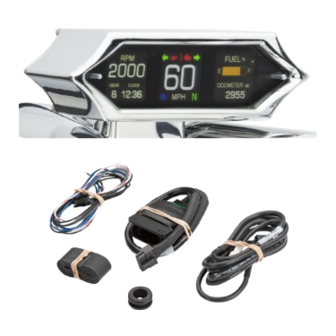
MODEL MLX-9X14 series
HARLEY CAN SPEEDOMETER/TACHOMETER
(Only for H-D CAN bus motorcycles)
.
Please read this before beginning installation or wiring
IMPORTANT NOTE!
This gauge has an odometer preset option that is only available one time
within the first 100 miles (160 km) of operation. See ODOMETER PRESET MENU for instructions.
MAN #650778A
Advertisement
Table of Contents

Related Manuals for Dakota Digital MLX-9X14 Series


Summary of Contents for Dakota Digital MLX-9X14 Series
- Page 1 MODEL MLX-9X14 series HARLEY CAN SPEEDOMETER/TACHOMETER (Only for H-D CAN bus motorcycles) Please read this before beginning installation or wiring IMPORTANT NOTE! This gauge has an odometer preset option that is only available one time within the first 100 miles (160 km) of operation. See ODOMETER PRESET MENU for instructions.
-
Page 2: Table Of Contents
TABLE OF CONTENTS Mounting Page 2 Wiring Page 3 Display Features Page 6 Operations Page 7 Setup Menu Page 8 Setup Steps Page 10 Trouble Shooting Page 18 Warranty Page 20 MOUNTING A mounting bracket must be purchased for your application. ❖... -
Page 3: Wiring
Wiring Diagrams Plug layout in back of gauge The interface harness allows the stock H-D CAN bus harness to adapt to the MLX-9x14 Wire color of accessory plugs looking into the plug with the wire. A 6-pin input harness is for the optional Oil pressure and Oil temp sensors (supplied). MAN #650778... - Page 4 OPTIONAL MBM HARNESS 394184 MBM harness interfaces direct to Dakota Digital Motorcycle Bus interface Modules ADDITIONAL AND OPTIONAL INPUTS 6 PIN CONNECTOR 3942165 GRAY wire Optional oil pressure sensor signal (SEN-1039) BLACK wire (bottom row) Optional oil pressure sensor ground (SEN-1039)
- Page 5 White wire from sensor OPTIONAL OIL TEMPERATURE To read oil temp of the engine, the Dakota Digital part number SEN-1043 or SEN-1044 must be used. The SEN-1043 is a one-wire sender with 1/8” NPT threads. ➢ Connect the terminal on the end of the sensor to the indicator harness BLUE wire.
-
Page 6: Display Features
SYSTEM FEATURES INDICATORS INFORMATION DISPLAYS There are 5 reading locations available to display information. They are labeled LEFT TOP, LEFT BTM, CENTER, RIGHT TOP, RIGHT BTM, respectively. The center location has 3 selectable readings that can be displayed, speed, tach or gear. The other locations can show any of the information readings listed below. -
Page 7: Operations
Operation, Clock Set, Service Reset FUNCTION SWITCHES The function switches seen on the face of the gauge serve multiple purposes. • In normal operating mode, the switches can change what is displayed on the outer LCDs. • They can also reset a tripmeter mileage, or performance data. •... -
Page 8: Setup Menu
Programming SETUP MENU The MLX 9X14 series can also be setup using the Apple© or Android ‘Dakota Digital Motorcycle’ app. The gauge MUST be in setup before using the app, (only Android must be paired before opening the app). The function switches are used to enter setup mode. - Page 9 Main Menu Sub Menu Description OIL PSI Enable/Disable option oil pressure reading LOW WARNING Set low warning point TEST Display sender voltage for troubleshooting BACK Turn Oil PSI option off BACK __________________________________________________________________________________________________________ FUEL SENDER Disable option fuel level reading HD 2004 Early H-D, 73-to-10-ohm sender HD 2011 DYNA 11...
-
Page 10: Setup Steps
Entering Setup Setup can be entered by a couple of means: ➢ Press and hold either switch and turn the power on. ➢ Hold both switches at the same time after the power is on. ➢ For LEARNING Gears, engine must be running while in setup mode. Entering setup for gear learning –... - Page 11 Setup Menus - continued DIAGNOSTICS - Diagnostics mode for checking/clearing trouble codes • The “run/kill” switch on the bike MUST be ON prior to running diagnostics. • When “> DIAGNOSTICS” is displayed, hold either switch until “RELEASE” is displayed, and release the switch. •...
- Page 12 SPEED - Speed setup menu • Tap either function switch until “> SPEED” is displayed. • When “> SPEED” is displayed, hold until “RELEASE” is displayed, and release the switch. • The selectable options are: “ADJUST”, “UNIT”, “SERVICE RESET”, “PRESET ODO”, or “BACK”. •...
- Page 13 • The display options are “SEN-1043”, “SEN-1044” and “BACK”. • Tap either switch to match to the optional sender you purchased from Dakota Digital. • Press and hold either switch on the selection, until “RELEASE” is displayed, and release. HIGH WARNING High oil temperature warning setup •...
- Page 14 OIL PSI - Engine oil pressure setup menu • Only valid when optional SEN-1039 pressure sender is purchased from Dakota Digital. • When “> OIL PSI” is displayed, press and hold either switch until “RELEASE” is displayed, and release. •...
- Page 15 FUEL - Fuel level setup menu (continued RANGE TO EMPTY Distance to empty (fuel) setup ❖ The range to empty option will calculate an estimate of miles until empty with true fuel senders. Will NOT work with Dyna or Sportster models. ❖...
- Page 16 DISPLAYS - Message display option menu ❖ Refer to graphic on page 6 for indicator and message locations. • When “> DISPLAYS” is displayed, press and hold either switch until “RELEASE” is displayed, and release. • The display will show “LEFT TOP”, “LEFT BTM”, ”CENTER”, “RIGHT TOP”, RIGHT BTM”, “MBMs”, or “BACK”. •...
- Page 17 GEAR - Gear indicator setup ❖ No gear indication will show until programming is done. ❖ Gear readout will display with clock on the LCD location of your choice. ❖ This feature will work with various transmissions up to seven speed models. ❖...
-
Page 18: Trouble Shooting
Troubleshooting guide Problem Possible cause Solution Gauge will not light up No battery power on stock Red/Orange wire Inspect stock harness Check battery fuse Test Brown wire on DD 12 pin for volts No ground on stock Black/Green wire Inspect stock harness Test Blue wire on DD 12 pin for ground No CAN data from ECU Verify ECU is operational... - Page 19 NOTES: MAN #650778...
-
Page 20: Warranty
SERVICE AND REPAIR DAKOTA DIGITAL offers complete service and repair of its product line. In addition, technical support is available to help you work through any questions or problems you may be having installing one of our products. Please read through the Troubleshooting Guide. There, you will find the solution to most problems.
Need help?
Do you have a question about the MLX-9X14 Series and is the answer not in the manual?
Questions and answers