Table of Contents
Advertisement
Quick Links
Please read this before beginning installation or wiring.
POWER
Connect the red wire from the main harness to accessory power from the ignition switch. In addition to
powering the display system, this is also where the low voltage detection circuit monitors the electrical system
voltage.
A good quality, solid state ignition switch should be used. The contacts on a mechanical "bar" switch can
bounce due to the vibration and cause the system to momentarily loose power and reset itself.
Never connect this to a battery charger alone. It needs to have a 12 volt battery connected to it. Battery
chargers have an unregulated voltage output that will cause the system to not operate properly.
GROUND
The black wire is the main ground for display system. This should be connected directly to the negative
cable on the battery. Connecting to a tank or frame ground can cause a weak or intermittent ground connection. A
poor ground connection can cause improper or erratic operation.
NEUTRAL, TURN SIGNAL & HIGH BEAM INDICATORS
The right turn, left
turn, and high beam indicators
are activated by 12 volts at
their respective hook-up wires.
The right turn signal
wire is green, the left turn
signal wire is orange, and the
high beam wire is purple.
These can be connected to
the same wires that the
indicator lights are connected
to. The display system wire
colors may not match the wire
colors in your electrical wire
harness.
The neutral indicator
is activated when the blue wire is grounded. Connect this wire to the neutral switch or to the negative side of the
neutral indicator light. When the indicator is activated, an N will be lit up to the right of the speedometer.
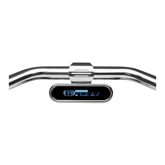
TRIP RESET & FUNCTION SWITCH
The push button switch is found on the front face of the display. To reset the trip mileage, press and hold
the switch in. Pressing the switch while turning power on will enter the setup menus.
MODEL HLY-6000
BAR MOUNT
Speedometer/TACHOMETER
INFORMATION SYSTEM
Advertisement
Table of Contents
Troubleshooting

Related Manuals for Dakota Digital HLY-6000


Summary of Contents for Dakota Digital HLY-6000
- Page 1 MODEL HLY-6000 BAR MOUNT SPEEDOMETER/TACHOMETER INFORMATION SYSTEM Please read this before beginning installation or wiring. POWER Connect the red wire from the main harness to accessory power from the ignition switch. In addition to powering the display system, this is also where the low voltage detection circuit monitors the electrical system voltage.
- Page 2 SPEEDOMETER Failure to calibrate the speedometer may cause your odometer mileage to increase very rapidly. The speed input connector plugs into the speed sensor to tell how fast you are traveling. On cable driven applications, the external sensor connects to the speedometer cable and provides the electric signal. The sensor is normally bolted directly to the bottom of the speedometer, but can also be remote mounted.
- Page 3 TACHOMETER The tachometer is used by connecting the yellow wire from the main harness to the negative side of the coil or to an ignition module tach output. The tachometer is adjustable for 1 – 15 cylinder settings. The 1 cylinder setting is used for single-fire ignition systems without a buffered tach output.
- Page 4 MOUNTING A mounting bracket must be purchased for your application. Some of the current brackets are: BKT-5001 1” bar mount, BKT-5002 flat triple-tree mount, BKT-5003 35° triple-tree mount, BKT-5004 1-1/4” bar mount, BKT-5005 1- 1/2” bar mount, and BKT-5006 1” riser bar mount. The bar mount brackets can be used for above-the-bar mounting or below-the-bar mounting.
- Page 5 This control module does NOT plug directly into the stock connector on 2004 and newer motorcycles. The typical color code for the stock wiring harness is provided to help in wiring. Dakota Digital does not guarantee that this is correct for all models and should only be used for reference. Not all wires will be found in all bikes.
- Page 6 Troubleshooting guide. Problem Possible cause Solution Gauge will not light up Red wire does not have Connect to a location that has power. power. Black wire is not getting Connect ground to a different location. a good ground. Display is not connected to Check cable between display and controller.
- Page 7 1-10 volts ac (make sure the meter is set to AC volts and not DC volts for this check). WARRANTY All DAKOTA DIGITAL instruments are warranted free of defects in material and workmanship for 2 years from the date of purchase. In the event of a problem with one of our products within the warranty period, DAKOTA DIGITAL will replace or repair the instrument at no charge.
Need help?
Do you have a question about the HLY-6000 and is the answer not in the manual?
Questions and answers