Table of Contents
Advertisement
Quick Links
Advertisement
Table of Contents

Subscribe to Our Youtube Channel
Summary of Contents for Daikin MC707PVM
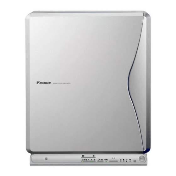
- Page 1 OPERATION MANUAL MODEL MC707PVM PHOTOCATALYTIC AIR PURIFIER...
-
Page 2: Table Of Contents
It is the function of quickly decomposing odor and harmful gas by generating oxidative high-speed electron within the air cleaner. (It is safe because high-speed electron is generated and Model MC707PVM disappeared within the system.) Required power supply 1ø220-240V (Streamer discharge fizzes but it is not abnormal.) -
Page 3: Safety Precautions
Safety Precautions • • Keep this manual where the operator can easily find them. Do not use outdoors or where exposed to direct sunlight. • Direct sunlight can weaken remote controller signal reception Read this manual attentively before starting up the unit. sensitivity and discolor the casing. -
Page 4: Names And Operation Of Each Part
Names and Operation of each Part Main unit Front Shock-absorbing material (cardboard) Be sure to remove the shock-absorbing material before operating. (page 5.) Pleated filter Rear 1 Front panel 14 Air inlet 2 Main unit display 15 Remote controller storage slot (page 4.) Shows operation status. - Page 5 Main unit display 1 Air intake for dust sensor 4 Automatic operation indicator (yellow) Air is taken in from here and the dust sensor detects the dirty state Lit during automatic operation. of the air. 5 Airflow rate indicator (green) (page 7.) 2 Clean monitor (Dust) Lit by the set airflow rate setting.
-
Page 6: Preparation Before Operation
Preparation Before Operation Remote controller setup Remote controller • Do not drop or place the remote controller in water. 1. Remote controller (Damage may occur.) preparations • Do not press the remote controller buttons with sharp objects. • Battery is already set in the remote (Damage may occur.) controller but the remote controller •... - Page 7 Attaching the bio-antibody filter 3. Attach the pleated filter. • Remove the pleated filter from the bag. 1. Remove the pre-filter. Pleated filter The side with the three • Remove by pulling out in front while holding the tabs on top of the holes goes up.
-
Page 8: How To Operate
Preparation Before 4 When you want to quickly clean the air Press the “ ” [TURBO] button. Operation • A high airflow rate will quickly remove any dirtiness in the air. • This is convenient to use when cleaning. 5 When you want to remove pollen Press the “... -
Page 9: Care And Cleaning
Care and Cleaning Cleaning chart Cleaning the air inlet for the dust/odor sensor For cleaning, remove each part in the number order. • Clean dusts clogged in For restoring each part, follow the opposite order. the air inlet for the dust/ CAUTION odor sensor. - Page 10 Care and Cleaning Cleaning the pre-filter NOTE It is recommended to clean the pre-filter every two weeks. • Securely close the panel. Failing to do so may cause activation of 1. Remove the front panel. the safety switch and out of unit operation. •...
- Page 11 Replace a pleated filter 5) Insert the pleated filter into the left and right hooks. (Replace the pleated filter when the “replace indicator” on the main unit display turns on or blinks.) 6) Secure the pleated filter with the tape. turn on 1.
- Page 12 Care and Cleaning Clean the plasma ionizer 3. Remove the bio-antibody filter. • Remove the bio-antibody filter from hooks (2 locations) at top of (If “cleaning sign” on the main unit display blinks) the plasma ionizer. Top hooks (2 locations) Blink CAUTION •...
- Page 13 Contents 1) Ionizing frame 2) Ionized wire 3) Streamer discharger 4) Opposing pole plate Remove each part. (page 11.) (page 11.) (page 11.) Vacuum dusts on the surface with a cleaner. Vacuum Caution • Do not remove the screws on the ionizer or streamer discharger. Breakdown may result. Soak in water or warm water with liquid mild detergent.
- Page 14 Care and Cleaning 3) Ionizing frame CAUTION • Clean off the resin part with a soft cloth. • Use a cotton bud to wipe off dirt of odd-shaped area where • When cleaning the unit, be careful not to cut your hands with the your finger does not reach.
- Page 15 Assembling the plasma ionizer 1. Attach the opposing pole plates. 2. Attach the streamer discharger. 1) Securely insert the opposing pole plate into the hooks (2 locations 1) Insert bottom of the streamer discharger to the ionizer frame. in the middle) of the plasma ionizer. Insert downward 2) Attach the opposing pole plate while opening the knobs (one at a 2) Insert top of the streamer discharger.
- Page 16 Care and Cleaning Cleaning the deodorization catalytic unit NOTE • Vacuum dusts with a • If the operation of 4. is not performed, the unit will not return to cleaner without normal operation mode. If the operation of 4. is performed, during removing from the the settings, the settings will not be correct.
-
Page 17: Frequently Asked Questions
Frequently asked questions Question Answer 1. The dust sensor does not This is due to dusts built up in the dust sensor. change from the red (green) Vacuum dusts from the air inlet with a crevice nozzle of a cleaner and then manually operate the unit for lamp. - Page 18 MEMO / English...
- Page 19 3P167171-3E M05B114C (0608) HT...


Need help?
Do you have a question about the MC707PVM and is the answer not in the manual?
Questions and answers