Table of Contents
Advertisement
Quick Links
Advertisement
Table of Contents

Related Manuals for Flintec FT-111


Summary of Contents for Flintec FT-111
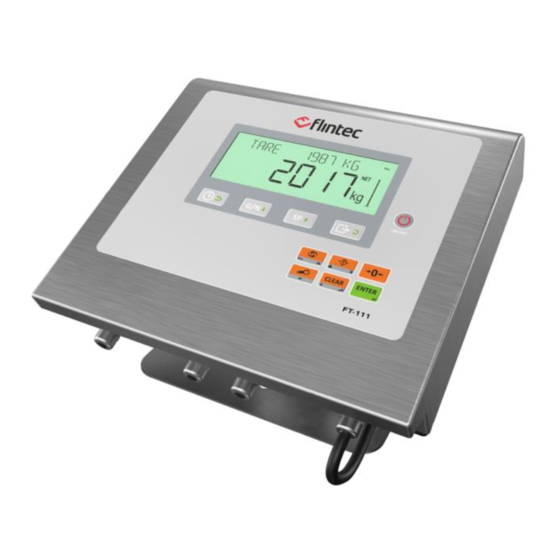
- Page 1 FT-111 User Manual FT-111 Weighing Indicator User Manual Flintec www.flintec .com...
-
Page 2: Table Of Contents
Step 3: Open the Housing / Close the housing ....................... 19 Step 4a: Analogue Load Cell Connection ......................... 19 Step 4b: Digital Load Cell Connection (Only FT-111 D) ..................20 Step 5: RS 232C Serial Ports ............................21 Step 6: RS 485 Serial Port ............................. 22 Step 7: Ethernet TCP/IP .............................. - Page 3 11.9.4 Profibus DP Data Structure ............................102 11.10 Profinet ....................................103 11.10.1 Electrical Connection ..............................104 11.10.2 Data Format ................................104 11.10.3 Profinet Parameters ..............................105 11.10.4 GSDML Configuration .............................. 105 FT-111, User Manual Rev. 2.0.0, June 2022 Page 3 of 137...
- Page 4 Powerlink Data Structure ............................118 Appendix 1 Data Structure Profibus, Profinet, EtherNET/IP, EtherCAT, CC-Link, Powerlink ......................119 Appendix 2: Data Structure CANopen ............126 14 Error Codes ........................135 FT-111, User Manual Rev. 2.0.0, June 2022 Page 4 of 137...
-
Page 5: Safety Instructions
Flintec reserves the right to revise this manual and alter its content without notification at any time. Neither Flintec nor its affiliates shall be liable to the purchaser of this product or third parties for damages, losses, costs, or expenses incurred by purchaser or third parties because of: accident, misuse, or abuse of this product or unauthorized modifications, repairs, or alterations to this product, or failure to strictly comply with Flintec operating and maintenance instructions. -
Page 6: Introduction
Digital inputs and outputs of the instrument can be programmed as a Remote IO on the fieldbus. This feature The scales equipped with FT-111 weighing terminal can be used in all kinds of industrial areas up to harsh, wet, and hygienic environments with its fast and efficient cleaning that was designed and built according to the international guidelines. - Page 7 500 Ω (current output) Min load resistance 10 kΩ (voltage output) Profibus DPV1 (optional) Data rate Up to 12000 kbit/s with automatic baud rate detection GSD file Generic GSD-file provided FT-111, User Manual Rev. 2.0.0, June 2022 Page 7 of 137...
- Page 8 Line, Tree, Star or Daisy-chain topology depending on physical media Switched Ethernet transmission with shielded twisted pair cables and RJ-45 Installation connectors. Isolation Galvanically isolated bus electronics Response speed Up to 4 ms. response delay after read/write commands. FT-111, User Manual Rev. 2.0.0, June 2022 Page 8 of 137...
- Page 9 Sizes ( W x H x D ) Wall type : 260 x 200 x 64 mm ( Weight 2,3 kg ( 5,07 lb ) Packing sizes Weight packed 3,2 kg ( 7,05 lb ) FT-111, User Manual Rev. 2.0.0, June 2022 Page 9 of 137...
-
Page 10: Housing
This kit can be used to install the weighing terminal on to the desk or to the wall. Its mounting dimensions and adjustment angles are shown below. Mounting part Side view Rear part of indicator FT-111, User Manual Rev. 2.0.0, June 2022 Page 10 of 137... - Page 11 This kit can be used to install the weighing terminal on to the column of the platform. Its mounting dimensions and adjustment angles are shown below. Mounting part Side view FT-111, User Manual Rev. 2.0.0, June 2022 Page 11 of 137...
-
Page 12: The Front View And Key Functions
RONT IEW AND UNCTIONS Figure 3.1 Front view of FT-111 ISPLAY The bright and wide-angle LCD display of the FT-111 is shown below. FT-111, User Manual Rev. 2.0.0, June 2022 Page 12 of 137... - Page 13 Announces the weight value is in the centre of zero range. Announces the weighing is not stable. After stabilization of the weighing, this symbol disappears. Announces the keys are locked. Announces the battery charging level. FT-111, User Manual Rev. 2.0.0, June 2022 Page 13 of 137...
-
Page 14: Keypad
3.2 K EYPAD The keys and the key functions of FT-111 in usage are: On: Press the key to switch on the weighing terminal. Page 28 Off: Press the key more than 2 seconds to switch off the instrument. Page 30, Date &... -
Page 15: Installation
For cable connections of different thicknesses, as seen in Figure 4.1 there are 3 interlocking gaskets with different diameters, indicated as B, C, and D, inside the glands used in the FT-111 weighing terminal. Depending on the thickness of the cable, remove the gaskets B and C respectively, pass the cable through the gland and tighten it. -
Page 16: Electrical Connection Recommendations
If the energy condition of your plant is not good enough, prepare a special power line. The quality of your plant grounding will provide weighing accuracy and the safety of FT-111. If grounding of your plant is not good enough, prepare a special power line and grounding. -
Page 17: Installation Steps
Before starting the installation, Select the weighing terminal location. Refer to recommendations in the previous section. 2. Prepare the Protective Earth (PE) cable to grounding the FT-111 housing. The protective earth should be as good as possible for scale reliability. - Page 18 Install the small part of the kit Assemble the kit as seen in the Install the weighing terminal to to the column. picture. the kit with 4 pcs M5 x 15 mm screws. FT-111, User Manual Rev. 2.0.0, June 2022 Page 18 of 137...
-
Page 19: Step 3: Open The Housing / Close The Housing
Figure 4.6. In 4-wire installations the sense and excitation pins with the same polarity should be short circuited at the connector side. If you have junction box in your system, use 6 wire cable between FT-111 and the junction box, and short circuit these pins at junction box for better performance. -
Page 20: Step 4B: Digital Load Cell Connection (Only Ft-111 D)
Connect the load cell cable shield to the housing (recommended to increase the EMC immunity against disturbances) or shield pin of the load cell connector. Step 4b: Digital Load Cell Connection (Only FT-111 D) The digital load cell wiring should be made carefully before energizing to avoid FT-111D and load cells from damages. -
Page 21: Step 5: Rs 232C Serial Ports
Step 5: RS 232C Serial Ports FT-111 weighing terminal has 2 x RS232C serial ports on the main board which are galvanically isolated from other circuitry to increase the EMC immunity. RS232C serial ports are named as RS232C-1 and RS232C-2 in set up menu and as Int 1 and Int 2 on the electronic board. -
Page 22: Step 6: Rs 485 Serial Port
Step 6: RS 485 Serial Port FT-111 weighing terminal has a RS485 serial port on the main board. The use of this galvanically isolated serial port and its specifications are described in the Table 4-4 and its pin configuration is shown in Table 4-5. -
Page 23: Step 8: Usb Port
Figure 4.12 - HUB connection The PC connection cabling is done via a cross cable as shown below. IP address blocks and gateway address of FT-111 and PC should be the same in cross connection. Figure 4.13 - PC connection with cross cable Important note: Disconnect IndFace2x software before Ethernet interfacing. -
Page 24: Step 9: Alibi Memory
Step 9: Alibi Memory (option If you install the alibi memory to the main board, order Alibi memory SD card from Flintec or dealer. The alibi memory SD card should be inserted into the SD1 card slot which is between load cell terminal and metal box of the analogue digital converter. -
Page 25: Step 12: Scale Setup And Calibration
You may start to use the scale for weighing after setting it up and calibration. We recommend testing your peripheral interfaces before starting to use the scale in your application. FT-111, User Manual Rev. 2.0.0, June 2022 Page 25 of 137... -
Page 26: Installation Of Optional Boards
If you need additional gland, Install Ex-gland which is supplied together with option board to instead of a blind plug. 8. Install cables to the option board as described in the related sections. FT-111, User Manual Rev. 2.0.0, June 2022 Page 26 of 137... -
Page 27: Cleaning
Disconnect the instrument from power source before start cleaning for your safety. Cover the open glands. FT-111 Weighing Terminal is designed for using in wet, hygienic, and harsh environment. To maintain the instrument, never use harsh abrasive cleaners or solvents. Wipe the instrument with a soft cloth slightly dampened with warm soapy water or with mild detergent. -
Page 28: Functions
UNCTIONS ASIC UNCTIONS Switching on The instrument will be switched on after pressing the power on / off key. FT-111 will start weighing operation after announcing the name and software version, load date and display testing. Switching off The instrument will be switched off after pressing the power on / off key for more than 2 seconds. [ - OFF - ] message appears short time on the display before power off. -
Page 29: Advanced Functions
Printout format can be selected from parameter 161. Flintec PC software is used to program EPL printout data and download into the instrument for free programming the data output or for label printing including barcode. Refer to page 51, and 42 for details. - Page 30 Key lock FT-111 has a capability to lock the keys to avoid unauthorized person´s interfering. The key(s) which would be locked are programmed in the setup at sub-block 34- . Lock the keys: Press key for more than 2 seconds. [PASSWORD: ] prompt appears on the display.
-
Page 31: Backup And Restore (With Sd Card)
IMPORTANT NOTE: To back up FT-111 , use an SD card with 16Gb maximum and formatted as FAT32. For on the PC. Set-up and calibration data of the FT-111 can be copied to an SD card to back up the instrument. After restoring this data to the instrument, you may go on operation without entering any data. -
Page 32: Setup, Backup And Restore Via Indface2X Software
2. PC to FT-111 connection can be done in two ways. a. Direct connection via RS232/485/Ethernet/USB b. Via local area network. If PC and FT-111 are connected to the same local area this connection can be made. After Ethernet connection enter the IP number of FT-111 to the terminal program. -
Page 33: Digital Inputs And Outputs
Digital inputs and outputs are set to their functions in sub-blocks 35- and 36-. Digital inputs can be programmed for zeroing, taring, print etc. in sub-block 35-. Digital outputs can be programmed for the different functions as described below. FT-111, User Manual Rev. 2.0.0, June 2022 Page 33 of 137... -
Page 34: Digital Inputs
S AIN Free set point of absolute indicated weight The digital output is activated with comparing the set point value and absolute indicated weight value as shown in the figure below. FT-111, User Manual Rev. 2.0.0, June 2022 Page 34 of 137... - Page 35 The digital output is activated with comparing the set point value and absolute net weight value as seen below. S NET Free set point of net weight The digital output is activated with comparing the set point value and net weight value as seen below. FT-111, User Manual Rev. 2.0.0, June 2022 Page 35 of 137...
- Page 36 Digital outputs which are not used at this mode can be programmed freely to any other function. For example, if SP5 is not needed to control, it can be programmed to the zero range to produce empty signal. FT-111, User Manual Rev. 2.0.0, June 2022...
- Page 37 The digital output is activated at the displayed weight value is stable. Error The digital output is activated when any Error is announced on the display. Remote Output of the PLC via fieldbus or BSI FT-111, User Manual Rev. 2.0.0, June 2022 Page 37 of 137...
- Page 38 4. Repeat from step 2 for entering following set points. 5. The FT-111 returns to the operation after displaying set point 5 and entering its value, 6. Press key to return operation at any step.
-
Page 39: Rs232 And Rs485 Data Outputs
If you transmit ASCII codes of P(print), Z(zero), T(tare) or C(clear) letters to the serial port of FT-111; it will act like the related key is pressed. -
Page 40: Fast Continuous Data Output
PC or to any host. The data output structure is; CN: 71 G: 3.007kg T: 1.001kg N: 2.006kg *ALB: 3 13 3 13 3 13 4 12 FT-111, User Manual Rev. 2.0.0, June 2022 Page 40 of 137... - Page 41 1.675 kg Gross/Tare/Net * Thank you * 3.097 kg weights * Thank you * 26F1 Includes only Gross or 26F2 Includes Gross or Gross\ Net weight value Tare\Net weight values FT-111, User Manual Rev. 2.0.0, June 2022 Page 41 of 137...
-
Page 42: Epl Format
Figure 7.1- Sample of the label printout of FT-111 which is designed in EPL format. If the label design can be saved into the printer, the default of EPL format of FT-111 can be transferred to the printer to print a designed label. The default of EPL format is as;... -
Page 43: Programming And Calibration
ROGRAMMING AND ALIBRATION You will find the programming and calibration procedure of FT-111 weighing terminal in this section. The arrows on the lower right corner of the keys under the display indicate the function of the keys in programming menu. The basic meanings of these keys are;... -
Page 44: Entering To The Programming And Calibration
[ WAIT ] message appears on the display for a little while, and the weighing terminal returns to the weighing mode. WARNING: Do not forget to switch off the instrument and bring the calibration DIP switch position to the FT-111, User Manual Rev. 2.0.0, June 2022 Page 44 of 137... -
Page 45: Programming And Parameters
ROGRAMMING AND ARAMETERS FT-111 weighing terminal is programmed under the seven main blocks in the programming menu which are serial interface, configuration, application, scale, calibration, metrology, and diagnostic. Main blocks in the programming menu are displayed like [1-- INTERFACE ] and sub-blocks are displayed like [11- RS232C-1 ]. -
Page 46: [1-- Interface] Interface Block
MBLH Modbus RTU Low-High format Press key to select output format different than Flintec´scontinuous data format while the selection is CONT in the information display. Available functions are seen on the weight display after pressing key sequentially. Press key after selecting the data format. - Page 47 Modbus RTU High-Low format MBLH Modbus RTU Low-High format Press key to select output format different than Flintec continuous data format while the selection is CONT in the information display. Available functions are seen on the weight display after pressing key sequentially.
- Page 48 Modbus RTU High-Low format MBLH Modbus RTU Low-High format Press key to select output format different than Flintec continuous data format while the selection is CONT in the information display. Available functions are seen on the weight display after pressing key sequentially.
- Page 49 High speed continuous data output BSI format for PC, PLC interface Press key to select output format different than Flintec continuous data format while the selection is CONT in the information display. Available functions are seen on the weight display after pressing key sequentially.
- Page 50 Modbus TCP High-Low format MBLH Modbus TCP Low-High format Press key to select output format different than Flintec continuous data format while the selection is CONT in the information display. Available functions are seen on the weight display after pressing key sequentially.
- Page 51 [ 15D DELAY : 050 format data. Remote IP address. (Client mod) If FT-111 Ex2 is to be connected to a remote device automatically [ 15E REMOTEIP : 000 either at startup or when exiting the programming menu IP address of the device must be entered.
- Page 52 [ 177 LF AFTE : +4 Line feed after printout (Press key to change ) + = Forward , - = Backward Example: -2 means 2 line feed backward. FT-111, User Manual Rev. 2.0.0, June 2022 Page 52 of 137...
- Page 53 Page 101 [ 191 FORMAT : INTG Data format of the Profibus FT-111, User Manual Rev. 2.0.0, June 2022 Page 53 of 137...
- Page 54 SUB MASK : 000 Subnet mask address of Ethernet port. Default is 255.255.255.000 [ 195 GATEWAY : 253 Gateway address. Default is 192.168.16.253 [ 19A MAC ADR MAC address AA:BB:CC:DD:EE:FF FT-111, User Manual Rev. 2.0.0, June 2022 Page 54 of 137...
- Page 55 : INTG Data format of the Powerlink INTG Signed 32 bit integer, no decimal point implied. FLOA 32 bit float, decimal point implied. [ 192 ADDRESS : 001 Node address FT-111, User Manual Rev. 2.0.0, June 2022 Page 55 of 137...
-
Page 56: [2-- Configuratio] Configuration Block
: MULT ] Taring. Disabled. MULT Tare with key, via serial interface or via digital input. GROS Tare with key, via serial interface or via digital input only at gross. FT-111, User Manual Rev. 2.0.0, June 2022 Page 56 of 137... - Page 57 Page 30 DATE SET Date setting XX.XX.XX Page 30 TIME SET Time adjust HH:MM Page 41 Consecutive number S. NAME : SCAL Scale name. Maximum 16 characters. Default is SCALE-1 FT-111, User Manual Rev. 2.0.0, June 2022 Page 57 of 137...
-
Page 58: [3-- Application] Application Block
: USE Tare key locking Not locked LOCK Locked [ 349 CLEAR : USE Clear key locking Not locked LOCK Locked [ 34A ZEROING : USE Zeroing key locking FT-111, User Manual Rev. 2.0.0, June 2022 Page 58 of 137... - Page 59 Page 34 [ 354 INPUT 4 : NO Digital input 4 Not used ZERO Zeroing TARE Taring Clear PRNT Print LOCK Key lock FBUS Controlled by fieldbus or BSI command. FT-111, User Manual Rev. 2.0.0, June 2022 Page 59 of 137...
- Page 60 The output is activated if the indication is lower than 0.5 kg. [ 367 OUTPUTS : IMME Output changing. IMME Immediately change even scale is not stable. STAB Change if the scale is stable. FT-111, User Manual Rev. 2.0.0, June 2022 Page 60 of 137...
-
Page 61: [5-- Scale] Scale Block
Power on zero. Disable. ± 2% 2%LK ± 2%, [ POWER ON ZERO ERR ] prompt cannot be erased. Call service. ± %10 15-5 + %15, - %5 ± %20 FT-111, User Manual Rev. 2.0.0, June 2022 Page 61 of 137... - Page 62 Select NO, g, kg, t, oz or lb. [ 522 RANGE : SING Scale range SING Single Range 2 x Multi Range 3 x Multi Range 2 x Multi Interval 3 x Multi Interval FT-111, User Manual Rev. 2.0.0, June 2022 Page 62 of 137...
- Page 63 The eccentricity correction of scale is performed manually 544 SET TO 1 NO ] M Temporarily set shift constants to 1 Normal operation (entered shift constants are used). Test mode (shift constants are equal to 1). FT-111, User Manual Rev. 2.0.0, June 2022 Page 63 of 137...
-
Page 64: [6-- Calb / Adjust] Calibration And Adjustment Block
The load weight used at the calibration is indicated here. ZERO COEFFIC This coefficient is determined the zero point of the scale. GAIN COEFFIC This coefficient is related with the gain factor of the scale. FT-111, User Manual Rev. 2.0.0, June 2022 Page 64 of 137... -
Page 65: [8-- Metrology] Metrology Block
This non-resettable and protected counter announces interfering [ 822 CONFIG COUNT quantity to the instrument. Count number increases at every exit from set-up mode. [ 823 NEXT VERIFIC Date of the next verification FT-111, User Manual Rev. 2.0.0, June 2022 Page 65 of 137... -
Page 66: [9-- Diagnostic] Diagnostic Block
CAL and ALL items can be loaded if the calibration dip switch is at ON position. WEB BACK UP Back up the instrument to the PC via web service. FT-111, User Manual Rev. 2.0.0, June 2022 Page 66 of 137... - Page 67 INSTRUMENT XX.XX OPTION XX.XX UPGRADE Firmware upgrade Call Flintec service or dealer to upgrade. DEFAULTS LOADING Press key or key again to enter this menu. DEFAULT Press key to go to the beginning of the sub-block or press key to go to beginning of the main-block.
-
Page 68: Calibration
Then continue with the following: Calibration involves emptying the scale then placing a known test weight on an empty platform and allowing the FT-111 to capture values for zero and span. Calibration is performed as; Press key at the [ 611 TEST WEIGHT ] prompt to start the calibration. -
Page 69: Zero And Span Adjustments
2. At the [ LOAD THE SCALE] [ XXXXXX ] prompt, the test weight value will be used for the calibration seen on the display. Enter the test weight value via keys. A minimum test load requirement is 20% of scale capacity for accurate calibration; FLINTEC recommends test load between 50% to 75% of the capacity. -
Page 70: Ecal Electronic Calibration
Dead load value is cancelled after automatic zero adjustment. FT-111, User Manual Rev. 2.0.0, June 2022 Page 70 of 137... -
Page 71: Gravity Adjustment
Note these coefficients to use them in case of calibration lost. Changing them slightly improves the scale accuracy without recalibration. Entering these values to another indicator may cause slightly reducing the weighing accuracy due to offset differences between two analogue digital circuits. FT-111, User Manual Rev. 2.0.0, June 2022 Page 71 of 137... -
Page 72: Digital Load Cells (Dlc)
Press key to address the load cell. After the following DLC number has appeared on the display, press key and the message [ 532 QUANTITY :XY ] appears. FT-111, User Manual Rev. 2.0.0, June 2022 Page 72 of 137... - Page 73 4. Press key until [ SAVE : YES ] prompt appears on the display. Press key to save the changes. FT-111, User Manual Rev. 2.0.0, June 2022 Page 73 of 137...
- Page 74 Parameter changes to [ 544 SET TO 1 : NO ], press key until [ SAVE : YES ] prompt appears on the display. Press key to save the changes into the memory. FT-111, User Manual Rev. 2.0.0, June 2022 Page 74 of 137...
-
Page 75: Sealing Of Approved Scale
10 S EALING OF PPROVED CALE Sealing With sticker FT-111, User Manual Rev. 2.0.0, June 2022 Page 75 of 137... -
Page 76: Optional Boards
Digital Inputs FT-111 digital inputs are independently programmable for zeroing, taring, clear, print, key lock and as a fieldbus Remote input in industrial weighing applications. Input connection diagram is shown in Figure 11.1. -
Page 77: Alibi Memory
Alibi memory requires the Alibi SD card at the SD1 card slot which is between load cell terminal and metal box of the analogue digital converter as shown in the pictures below. If you install the alibi memory SD card, order Alibi SD pack from Flintec or dealer. Figure 11.3- Location of Alibi SD card slot... -
Page 78: Activating Alibi Memory
3 times and key to access parameter 813. 3. Select the suitable criteria by pressing keys which are NUM (Alibi number), DATE (weighing date) or CN (consecutive number). FT-111, User Manual Rev. 2.0.0, June 2022 Page 78 of 137... - Page 79 The empty fields are indicated as [ ------- ] and transferred as [ NO RECORD ]; and the corrupted records are indicated as [ Error ] and transferred as [ CORRUPTED ]. FT-111, User Manual Rev. 2.0.0, June 2022 Page 79 of 137...
-
Page 80: Installation Of Sd Card
NSTALLATION OF Some features of the FT-111 need to be inserted into the SD card located close to the USB connector on the main board which is named as SD2. Some options might be activated by SD pack which should be supplied from Flintec. -
Page 81: Bsi Protocol To Interface With Pc And Plc
New generation FLINTEC weighing terminals launched on the market support the standardized command set BSI (Flintec Serial Interface) data form, depending on the functionality of the instrument. This easy data format gives the reliable and speedy interface advantages with communicating PLC or PC for process control or transactional applications. -
Page 82: Bsi-Base Commands
[ADR][Q][SP No][L][SIGN][SP [ADR][Q][STATUS] VALUE] Read set points [ADR][R][SP No][L] [ADR][R][STATUS][SIGN][SP VALUE] Read Status [ADR][S] [ADR][S][STATUS-1][STATUS-2] [STATUS-3] Tare [ADR][T] [ADR][T][STATUS] Read digital inputs [ADR][U] [ADR][U][STATUS][Inputs] Read digital outputs [ADR][V] [ADR][V][STATUS][Outputs] FT-111, User Manual Rev. 2.0.0, June 2022 Page 82 of 137... - Page 83 (gross weight is dynamic and 123.4) (under load) Comments The response is the gross weight value (stable or dynamic) or error status. Gross weight data is transmitted immediately after receiving command. FT-111, User Manual Rev. 2.0.0, June 2022 Page 83 of 137...
- Page 84 : 01F1 (Enable) 01F0 (Disable) Response : 01FA (Command is done successfully) 01FN (Command could not executed) Comments: Indicated weight value sends continuously. Continuous data format is [ADR][I][STATUS][SIGN][WEIGHT VALUE]. FT-111, User Manual Rev. 2.0.0, June 2022 Page 84 of 137...
- Page 85 : [ADR][Q][SET No][L][SIGN][SP VALUE] Response : [ADR][Q][STATUS] Example Command : 01Q01L+000123.4 Response : 01QA (123.4 loaded to SP1) 01QN (Could not loaded) 01QX (Decimal point of SP VALUE is mismatch) FT-111, User Manual Rev. 2.0.0, June 2022 Page 85 of 137...
- Page 86 (All 8 inputs are active) 01UN (Could not read inputs) Comments: Data lengths change according to number of digital inputs. Inputs are implemented to ASCII char of 4- INPUTS Bit wise ASCII FT-111, User Manual Rev. 2.0.0, June 2022 Page 86 of 137...
- Page 87 Weight must be in zeroing range for all operating modes. Status must be stable in 2 seconds time out delay. If so, Ack is send. If it cannot be stable in time out delay, Nack is send. FT-111, User Manual Rev. 2.0.0, June 2022 Page 87 of 137...
-
Page 88: Continuous Data Formats
ONTINUOUS ORMATS RELATED PARAMETERS: Parameters 111, 121, 131 and 141. Continuous data output can be programmed to some common formats besides Flintec continuous formats. To select one of the described formats below press the key sequentially. Press key to go to the next parameter. - Page 89 Unit of weight value are kg, g, lb, klb, N or kN as left aligned. Carrige Return ( 0D hex ) ® Sartorious Description Ignore Sign SP Indicated weight SP Unit CR LF Example FT-111, User Manual Rev. 2.0.0, June 2022 Page 89 of 137...
- Page 90 Sartorious. Rinstrum ® is a registered trademark of Rinstrum. ® Avery is a registered trademark of Avery Weigh-Tronix. ® Baster is a registered trademark of Baster. FT-111, User Manual Rev. 2.0.0, June 2022 Page 90 of 137...
-
Page 91: Analogue Output
IMPORTANT NOTE: The analogue output cable should be shielded. Connect the shield to the protective earth as described in the installation section. PARAMETERS: Sub-block 19- for analogue output set up. FT-111 has analogue output which is programmable to 4 20 mA, 0 20 mA, 0 5 V or 0 10 V. - Page 92 4 20mA / 0 20mA 0 5 V / 0 10 V Figure 11.6 - Analogue output connection Pin configuration of digital input and output connector is described on page 76. FT-111, User Manual Rev. 2.0.0, June 2022 Page 92 of 137...
-
Page 93: Modbus Rtu
11.7 M ODBUS FT-111 controller has a Modbus RTU interface over RS485 / RS232C serial port. This interface can be programmed to High-Low or Low- data formats and some companies using these formats. Two types are available as: 11.7.1 Modbus RTU Data Structure After programming RS485 / RS232C serial port for Modbus RTU, it can be used as a Modbus RTU slave on Modbus RTU network. - Page 94 Active Output-4 Output-5 40045 Setpoint 1 40047 Setpoint 2 40049 Setpoint 3 40051 Setpoint 4 40053 Setpoint 5 40057 Reserve 40087 Alibi number 40089 Net weight 40091 Tare weight FT-111, User Manual Rev. 2.0.0, June 2022 Page 94 of 137...
- Page 95 Single range 2 x MR 40155 Range 3 x MR 2 x MI 3 x MI 40157 MAX-1 Refer to parameter [522] on page Description 40159 Decimal point-1 XXXXOO XXXXXO FT-111, User Manual Rev. 2.0.0, June 2022 Page 95 of 137...
- Page 96 Instrument cannot be calibrating - Load cell signal is very low or too high Calibration Error - Calibration loading is not enough - Check test weight loading - Check load cell connections FT-111, User Manual Rev. 2.0.0, June 2022 Page 96 of 137...
- Page 97 DC variant or 1 VAC increment for AC variant. Millivolt value of active scale is indicated with 0.01 Load cell millivolt value mV increment. 40209 (only FT-111 ) For example: 2.34 mV is indicated as integer 234 value. 40211 defaults...
- Page 98 (Input-2 is active) Read digital outputs 01,03,00,2A,00,02,E5,C3 Answer of digital outputs 01,03,04,00,00,00,04,FB,F0 (Output-3 is Active) Read Set point-1 01,03,00,2C,00,02,05,C2 Answer of Set point-1 01,03,04,00,00,03,E8,FA,8D Load Set point 1 = 5000 01,10,00,2C,00,02,04,00,00,13,88,FC,B4 FT-111, User Manual Rev. 2.0.0, June 2022 Page 98 of 137...
-
Page 99: Ethernet Tcp/Ip
TCP/IP THERNET Ethernet output of FT-111 is programmable to BSI command set, Continuous data output, Fast continuous data output, Modbus TCP/IP High-Low, Modbus TCP/IP Low-High. The first three data structures can be find in the related sections indicated in the table below. -
Page 100: Modbus Tcp Data Structure
Make the Ethernet parameter settings as defined on sub- Please find Modbus information in the web site of http://www.modbus.org For Modbus TCP/IP Command Table see page 93 For command samples see page 98: FT-111, User Manual Rev. 2.0.0, June 2022 Page 100 of 137... -
Page 101: Profibus Dp
45.45 kbps, 93.75 kbps, 187.5 kbps, 500 kbps, 1.5 Mbps, 3 Mbps, 6 Mbps and 12 Mbp instance exists. Refer to Profibus parameters, sub-block 19-, GSD file is available on www.flintec.com . There are LEDs near the Profibus connector which are: Ref. -
Page 102: Data Format
Figure 11.8. Figure 11.8 - GSD Configuration GSD Configuration Description Input 2 words Dword (FT-111 Output to PLC Input) Input 2 words Dword (FT-111 Output to PLC Input) Output 2 words Dword (PLC Output to FT-111 Input) -
Page 103: Profinet
You may change the port if there is any malfunction on port in usage. The Profinet interface is 100Mbit and full duplex. GSDML file for two port Profinet is on www.flintec.com There are a few announcement LEDs on the instrument to indicate the interface status as seen below. -
Page 104: Electrical Connection
Pin configuration of digital input and output connector is described on page 76. 11.10.2 Data Format Data format of weight value can be programmable for Floating point (IEEE 754) or Integer. Refer to parameter [ 191 ]. FT-111, User Manual Rev. 2.0.0, June 2022 Page 104 of 137... -
Page 105: Profinet Parameters
Profinet parameters can be adjusted by keys in programming mode. Refer to parameter block [ 19- ]. Additionally, Profinet parameters set up is done by EtherX PC software over Local Network Area or by IndFace2x. Both software are available on www.flintec.com . Note: 196. -
Page 106: Profinet Data Structure
Figure 11.13 - GSDML Configuration GSDML Configuration Description Input 2 word_1 Dword (FT-111 Output to PLC Input) Input 2 word_2 Dword (FT-111 Output to PLC Input) Output 2 word_1 Dword (PLC Output to FT-111 Input) Output 2 word_2 Dword (PLC Output to FT-111 Input) 11.10.5 Profinet Data Structure... -
Page 107: Ethernet/Ip
You may change the port if there is any malfunction on port in usage. The EtherNet/IP interface supports 10/100Mbit, full or half duplex operation. EDS file for two port EtherNet/IP is available on www.flintec.com There are announcement LEDs on the instrument to indicate the interface status as seen below. -
Page 108: Electrical Connection
PC should be the same in cross connection. Figure 11.16 - Cross PC connection Pin configuration of digital input and output connector is described on page 76. FT-111, User Manual Rev. 2.0.0, June 2022 Page 108 of 137... -
Page 109: Data Format
EtherNet/IP parameters can be adjusted by keys in programming mode. Refer to parameter block [ 19- ]. Additionally, EtherNet/IP parameters set up are done by EtherX PC software over Local Network Area or by IndFace2x. Both softwares on www.flintec.com Parameters... -
Page 110: Ethernet/Ip Data Structure
Figure 11.18 Configuration of module properties with EDS file Data Length Description ( FT-111 Output to PLC Input ) Input 2 words 1st Dword ( FT-111 Output to PLC Input ) Input 2 words 2nd Dword ( PLC Output to FT-111 Input ) -
Page 111: Ethercat
30 seconds later. C, E LINK/Activity LED LED State Description No link, no activity. Green Link sensed, no activity. Green, flickering Link sensed; activity exist. FT-111, User Manual Rev. 2.0.0, June 2022 Page 111 of 137... -
Page 112: Electrical Connection
Pin configuration of digital input and output connector is described on page 76. 11.12.2 Data Format Data format of weight value can be programmable for Floating point (IEEE 754) or Integer. Refer to parameter [ 191 ]. FT-111, User Manual Rev. 2.0.0, June 2022 Page 112 of 137... -
Page 113: Esi Configuration
EtherCAT data structures consist of 2 pcs Input-2 words and 2 pcs Output-2 words. ESI configuration for PLC programmers is shown in Figure 11.21. Figure 11.21 Configuration of module properties for Beckhoff Input/Output Definition Description FT-111 Output to PLC Input SubIndex 001 Dword ( DI TxPDO-Map FT-111 Output to PLC Input SubIndex 002... -
Page 114: Cc-Link
11.13 CC-L After setting related parameters you can communicate with FT-111 via CC-Link network. Supported CC-Link version is v1.10 and baud rates are 156 kbps (default), 625 kbps, 2,5 Mbps, 5 Mbps and 10 Mbps. There are LEDs near the CC-Link connector which are: Ref. -
Page 115: Data Format
-Link configuration for PLC programmers is shown in Figure 11.23. Figure 11.23 Station information Input/Output Definition Description FT-111 Output to PLC Input RWr0, RWr1 Dword Input ( Remote Register (RWr) RWr2, RWr3 Dword Input ( FT-111 Output to PLC Input... -
Page 116: Powerlink
LED State Description No error If the NETWORK ERROR LED is Off, a non-fatal error has been detected. If the NETWORK ERROR LED is On, a fatal event was encountered. FT-111, User Manual Rev. 2.0.0, June 2022 Page 116 of 137... -
Page 117: Electrical Connection
Pin configuration of digital input and output connector is described on page 76. 11.14.2 Data Format Data format of weight value can be programmable for Floating point (IEEE 754) or Integer. Refer to parameter [ 191 ]. FT-111, User Manual Rev. 2.0.0, June 2022 Page 117 of 137... -
Page 118: 3Xdd Configuration
PLC programmers is shown in Figure 11.26. Figure 11.26 Configuration of module properties with XDD file Data Length Description 1_Dword_Input_I2001_S01 Dword ( FT-111 Output to PLC Input ) 2_Dword_Input_I2001_S02 Dword ( FT-111 Output to PLC Input ) 1_Dword_Output_I2002_S01Out Dword ( PLC Output to FT-111 Input ) -
Page 119: Appendix 1 Data Structure Profibus, Profinet, Ethernet/Ip, Ethercat, Cc-Link, Powerlink
B30 B29 B28 B27 B26 B25 B24 B23 B22 B21 B20 B19 Dword (Only read) Table 12-1 Bitwise of a Dword FT-111 Output to PLC Input By default, Actual weight value is represented. Dword To represent other weight or calibration status, refer to next Dword. (INPUT) Dword... - Page 120 Expanded Commands List CMD Flag Toggles The command is applied successfully ALL Status (always 32 bit integer) Refer to 2 Dword of PLC Output to FT-111 Input. Bit Number 1st Dword (input) Description None No decimal point None Decimal point is X.X...
- Page 121 - If seen again, change the board. No Error Calibration Timeout - Restart calibration None Span None Not ready for calibration Ready for calibration Table 12-3 - Calibration status FT-111, User Manual Rev. 2.0.0, June 2022 Page 121 of 137...
- Page 122 PLC Output to FT-111 Input Next Dword defines the usage of this Dword. Dword (OUTPUT) Expanded Commands List Dword (OUTPUT) Not in use Command List Read Data Selection Description of Input 2 Dword (OUTPUT) Bit Number Descriptions Set / Reset digital outputs...
- Page 123 Here 1 Bit No Description Dec Commands Voltage of Power supply (Only FT-111 ) 00000000 0 The value is indicated with 0.1 VDC increment for DC variant or 1 VAC increment for AC variant. Load cell millivolt value 00000001 1 Millivolt of active scale is indicated with 0.01...
- Page 124 1 division more than Max Limit of 01010010 9 division more than Max (1) (2) Indication 2% more than Max 5% more than Max Table 12-4 - Expanded Command List FT-111, User Manual Rev. 2.0.0, June 2022 Page 124 of 137...
- Page 125 Dword (Input). Programming steps of frequent used commands: Reading a weight value: FT-111 Output to PLC Input 2 2. If there is not any error, read the weight value ( gross, net or tare ). Zero Calibration procedure: Check the Bit-0 of Calibration Status. it should be '1'(set) to start adjustment.
-
Page 126: Appendix 2: Data Structure Canopen
Unit Read command response of zero (T_UL1) By default, Actual weight value is represented. To represent other weight o FT-111 Output to PLC Input 2 Dword Bit Number TxPDO 1 (T_UL1) Description Digital Outputs Output bit status (Active = 1) - Page 127 10100 Not used 11110 Use the Expanded Command list 11111 (Refer to Table 13.3) CMD Flag Toggles The command is applied successfully By default, Actual weight value is represented. FT-111, User Manual Rev. 2.0.0, June 2022 Page 127 of 137...
- Page 128 ALL Status (always 32 bit integer) PLC Output to FT-111 Input. Bit Number Low Dword of TxPDO 1(T_UL1) Description None No decimal point None Decimal point is X.X None Place of decimal point Decimal point is X.XX None Decimal point is X.XXX None Decimal point is X.XXXX...
- Page 129 Calibration Status (always 32 bit integer) 1(R_UL1) of PLC Output to FT-111 Input. Bit Number Low Dword of TxPDO 1(T_UL1) Description Not in use No Error - Check the calibration DIP switch. No Error Scale unstable - Wait until scale become stable...
- Page 130 Command List Read Data Selection (R_UL1) B33-B37 bits defines the usage of this Dword. PLC Output to FT-111 Input RxPDO 1 (R_UL1) Bit Number RxPDO 1 (R_UL1) descriptions Set / Reset digital outputs Expanded Commands List (Refer to Table 13.3)
- Page 131 Apply commands which are listed in this table. B31-B0 D33-D37 bits defines the usage of this Dword. (1) Write this command after writing values to Low Dword of RxPDO then apply this command with New CMD. FT-111, User Manual Rev. 2.0.0, June 2022 Page 131 of 137...
- Page 132 ± 0,3d Auto Zero ± 0,5d 01000011 Tracking (1) (2) ± 1d ± 2d ± 3d Tare (1) (2) Multi tare 01000100 Tare only at gross 01000101 Stability ± 0,3d FT-111, User Manual Rev. 2.0.0, June 2022 Page 132 of 137...
- Page 133 (1) Write this command after writing values to Low Dword of RxPDO then apply this command with New CMD. (2) To access the related value, read Low Dword of TxPDO. FT-111, User Manual Rev. 2.0.0, June 2022 Page 133 of 137...
- Page 134 4. The Bit-0 of Calibration Status changes to '1'(set) at the end of the Span calibration. 5. If the Bit-3~Bit-10 of Calibration Status is '1'(set), check the description to understand the calibration error. FT-111, User Manual Rev. 2.0.0, June 2022 Page 134 of 137...
-
Page 135: Error Codes
RROR ODES FT-111 weighing terminal had been designed as a very reliable and virtually error free instrument. However, if there is an error occurs, do not attempt to repair the equipment before understanding what caused the error. Note the problems you have with your instrument and the error messages shown on the display. Then try to solve the problem according to the error table given below. - Page 136 - Check Alibi SD card. installed. - Change mainboard. Alibi SD card is not supplied E41 ALIBI FAULT - Install Flintec Alibi SD card. from FLINTEC. Alibi memory serial number - Format the alibi memory SD card. E42 NEW ALIBI error.
- Page 137 FT-111, User Manual Rev. 2.0.0, June 2022 Page 137 of 137...
Need help?
Do you have a question about the FT-111 and is the answer not in the manual?
Questions and answers