Advertisement
Quick Links
Advertisement

Subscribe to Our Youtube Channel
Related Manuals for Flintec FT-10


Summary of Contents for Flintec FT-10
- Page 1 FT-10 User Manual FT-10 Smart Process Indicator User Manual www.flintec.com...
- Page 2 Entries [14-] ..............................39 4.4.5 Scale Block [2--] ............................... 39 Calibration Block [3--] ............................40 4.5.1 Analogue Output Block [4--] (Only FT-10 AN) ....................44 4.5.2 Digital Output Functions [70-] ......................... 45 4.5.3 Metrological Data Block [8--] ........................... 45 4.5.4 Diagnostics [9--] ...............................
- Page 3 Profibus DP / Profinet Data Structure......................64 Profinet (only FT-10 PN) ..............68 Data Format ..............................69 Profinet Parameters............................69 GSDML Configuration and Data Structure ....................... 69 Ethernet TCP/IP (only FT-10 EN) .............70 10.1 Ethernet Parameters ............................71 10.2 Modbus TCP Data Structure ..........................72 CANopen (only FT-10 CO) ...............76...
- Page 4 Calibration Table ................102 Index ....................103 FT-10, User Manual, Rev. 3.0.1, June 2022 Page 3 of 105...
- Page 5 The information herein is believed to be both accurate and reliable. Flintec, however, would be obliged to be informed if any errors occur. Flintec cannot accept any liability for direct or indirect damages resulting from the use of this manual.
- Page 6 These instruments convert the low-level strain gage load cell analogue signal to digital signal in high resolution and accuracy to transmit digital data to PLC or PC. With a wide variety of interface, FT-10 instruments are used for any type of weighing processes and force measurement including tank and silo weighing, dynamic weighing, check weighing, filling, tension /compression force measurement etc.
- Page 7 Cable length: maximum 1000 m/mm² for 6-wire connection Communication RS-232 1200 to 115200 baudrate, 8N1 / 7O1 / 7E1 / 8O1 / 8E1 Response speed Up to 4ms response delay after read / write commands FT-10, User Manual, Rev. 3.0.1, June 2022 Page 6 of 105...
- Page 8 1200 to 115200 baudrate, 8N1 / 7O1 / 7E1 / 8O1 / 8E1 Response speed Up to 4 ms response delay after read/write commands Max Stations Up to 31 stations per segment FT-10 PB Profibus DPV1 (optional) Communication Data rate Up to 12000 kbit/s with automatic baud rate detection GSD file...
- Page 9 FT-10 PN Profinet (optional) Communication Data rate 100 Mbit/s, full duplex GSDML file Generic GSDML-file provided DHCP or manual IP assign over Indface1x PC Software. TCP/IP settings Device identity customization Topology Line, Bus, Star or Tree topology depending on physical media Installation Switched Ethernet transmission with shielded twisted pair cables and RJ-45 connectors.
- Page 10 FT-10 EC EtherCAT (optional) Communication Data rate 100 Mbit/s, full duplex ESD file Generic EDS-file provided Topology Line, Tree, Star or Daisy-chain topology depending on physical media Installation Switched Ethernet transmission with shielded twisted pair cables and RJ-45 connectors. Isolation...
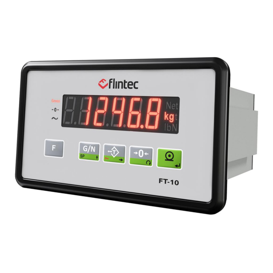
- Page 11 2.4.1 Display The weight display of FT-10 consists of 7-segments LED. At the right side of the display there are two LEDs for indicating the net and the units (standard kg), and on the left side of the display for indicating the gross, centre of zero and unstable status.
- Page 12 Print: Weight data and other information depending on the setup parameters are sent to a printer or a PC via serial port. 2.4.3 Key Lock FT-10 has an ability to lock the keys to avoid unauthorized people interfere. The key(s) which would be locked are programmed at parameter [115]. You can activate or deactivate this function by long pressing <...
- Page 13 FT-10 front and side view FT-10P rear view FT-10AN rear view FT-10IO & FT-10MB rear view FT-10PB rear view FT-10PN rear view FT-10EN rear view FT-10CO rear view FT-10, User Manual, Rev. 3.0.1, June 2022 Page 12 of 105...
- Page 14 FT-10EI rear view FT-10EC rear view FT-10CC type rear view FT-10PL type rear view FT-10, User Manual, Rev. 3.0.1, June 2022 Page 13 of 105...
- Page 15 If there are noise-generating equipment such as heavy load switches, motor control equipment, inductive loads etc., please be careful against the EMC interference in the cabinet. If possible, protect FT-10 instruments with the faraday cage or install them in separate section or install them far away from this kind of equipment. Connect parallel reverse diodes to the DC inductive loads like relays, solenoids etc.
- Page 16 In 4-wire installations the sense and excitation pins with the same polarity should be short circuited at the connector side. If you have junction box, use 6 wire cable between FT-10 and the junction box, and short circuit these pins at junction box for better performance.
- Page 17 4W-Load cell Junction box 6 Wire-cable FT-10 Indicator Shield Shield + Exc + Sig Shield - Sig - Exc Bridges 3.3.3 RS 232C Connection RS 232C port usage and specifications are shown in the table 4.1 Interfacing with PC or PLC, remote display connection,...
- Page 18 FT-10AN is programmable to 4 – 20 mA, 0 – 20 mA, 0 – 5 V or 0 – 10 V analogue output types. Analogue connections are done as indicated in Figure 4.5 and Figure 4.6 Figure 4.5 - FT-10 AN Voltage output connections Figure 4.6 - FT-10 AN Current output connections 3.3.6 Profibus Connection (only FT-10 PB)
- Page 19 The HUB connection cabling will be a direct connection as shown in Figure 4.9: Figure 4.9 - HUB connection The PC connection cabling will be done via cross cable as shown below. IP address blocks and gateway address of FT-10 and PC should be the same in cross connection.
- Page 20 The HUB connection cabling will be a direct connection as shown below: Figure 4.11 - HUB connection The PC connection cabling will be done via cross cable as shown below. IP address blocks and gateway address of FT-10 and PC should be the same in cross connection.
- Page 21 3.3.9 CANopen Connection (only FT-10 CO) CANopen connection is done with 4 wires as indicated in Figure 4.13. The data line ends must be equipped with 120-ohm bus terminating resistors. Figure 4.13 - FT-10 CO serial interface connections CANopen Connector pin configuration (DB9M) Signal...
- Page 22 The HUB connection cabling will be a direct connection as shown below: Figure 3.2 - HUB connection The PC connection cabling will be done via cross cable as shown below. IP address blocks and gateway address of FT-10 and PC should be the same in cross connection.
- Page 23 The HUB connection cabling will be a direct connection as shown below: Figure 3.5 - HUB connection The PC connection cabling will be done via cross cable as shown below. IP address blocks and gateway address of FT-10 and PC should be the same in cross connection.
- Page 24 3.3.12 CC-Link Connection (only FT-10 CC) CC-Link connection is done as indicated below in Figure 3.7. Figure 3.7 – FT-10CC interface connections CC-Link Connector pin configuration Signal Description PositiveRS485 Rxd/TxD NegativeRS485 Rxd/TxD Signal ground Cable Shield Protective Earth Warning : Connect the shield to the reference ground or shield pin of the power connector.
- Page 25 3.3.13 Powerlink Connection (only FT-10 PL) Powerlink connection is done as indicated below in Figure 3.8. Figure 3.8 – FT-10 PL interface connections Powerlink Connector pin configuration (RJ45) Signal Description Differential Ethernet transmit data + TX− Differential Ethernet transmit data −...
- Page 26 3.3.14 Digital Inputs FT-10 inputs are independently programmable for zeroing, taring, clear, print, key lock, peak, hold, and as a fieldbus input port. If the input is programmed as a fieldbus input port, the input status is transferred to the PLC by fieldbus command. Inputs: 12...28 VDC, 10 mA.
- Page 27 FT-10 instruments digital outputs can be used as a standard, threshold and window. Threshold and window outputs are also programmable with positive or negative polarity. Digital outputs of FT-10 are also programmable as a fieldbus port to control them Page 38 Page 45 with a fieldbus commands.
- Page 28 To enter the negative or positive value, long press < Tare > key while the set point value is seen on the display. Refer to parameter [ 130 ] on Page 38. FT-10, User Manual, Rev. 3.0.1, June 2022 Page 27 of 105...
- Page 29 2 set point values are entered. The output is active when the weight is between SP1_L and SP1_H. Inverse function is available. Refer to parameter [ 7-- ] on Page 45 FT-10, User Manual, Rev. 3.0.1, June 2022 Page 28 of 105...
- Page 30 Before power on the instrument, please make the required mechanical and electrical installations. After power on, you must program your FT-10 before field bus interfacing. Install IndFace1X to your PC. IndFace1X software is used for easy programming, calibration, and testing of FT-10 instruments. FT-10, User Manual, Rev.
- Page 31 4.1 Entering the Programming and Calibration There is a DIP switch on the rear side of FT-10 and its position should be “ON” (downwards) to change the metrological related parameters including calibration. There is no need to open the housing to change the position of this DIP switch. If there is not set- up DIP switch on the instrument for industrial usage, its position is always ON.
- Page 32 [Waıt] message will be seen on the display for a short time, and automatically get back to weighing mode. Especially for legal metrological usage, please don’t forget to turn the power off and switch the calibration DIP to “OFF” position to start the operation. FT-10, User Manual, Rev. 3.0.1, June 2022...
- Page 33 4.4.1 Serial Port, Printer and Fieldbuses [0--] Interface Block You can reach the parameters about serial interface of FT-10 indicator in this section. The data output modes can be used once except continuous data output. [00-] RS 232C Serial Port This sub-block includes the parameters about the 1 serial interface of FT-10.
- Page 34 5 : Modbus RTU Low-High Page 47 6 : Fast continuous mode ( * ) Warning : Use for Flintec remote displays interfacing. CR and LF should be enabled. [011 3] Baud Rate 0 : 1200 Baud 2400 Baud 2 : 4800...
- Page 35 [03-] Ethernet (Only FT-10 EN) This sub-block includes the parameters related with the Ethernet of FT-10 indicator. [030 4 ] Data Format 0 : No data transfer Page 47 1 : Continuous data output Parameter [040] (Page 35 2 : Print mode...
- Page 36 Available values are from 0 to 9. [048 1] Quantity of Copies X = 1,2….9 : Enter the label quantity for each weighing. Note: This function is valid only for 040 = 2 or 3. FT-10, User Manual, Rev. 3.0.1, June 2022 Page 35 of 105...
- Page 37 0 : Signed 32 bit integer, no decimal point implied 1 : 32 bit float, decimal point implied [051 000] Rack Address The Profibus rack address of FT-10 will be entered via keypad between 001 to 126. Note: After the address is changed, the device must be re-booted...
- Page 38 4.4.2 Configuration Block [1--] In this block the parameters take place which are being used to set FT-10 according to your application. [11-] Start Up [112 1] Tare Memory 0 : No. 1 : Tare value is stored at power off.
- Page 39 Page 45 8 : Control mode-1 (Refer to Page 45 9 : Control mode-2 (Refer to [131 0] Input 1 (only FT-10IO, FT-10MB, FT-10 AN, FT-10PB, FT-10PN, FT-10EN and FT-10CO, FT-10EI, FT-10EC, FT-10CC, FT-10PL) 0 : Not used 1 : Zero...
- Page 40 [207 0.3] Stability Period If the scale is stabile during this time, the scale is accepted as a stabile to process zeroing, tare, print etc. commands. It can be entered up to 9.9 sec. FT-10, User Manual, Rev. 3.0.1, June 2022...
- Page 41 In the second stage of verification, the gravity acceleration of the place that the weighing instrument will be used should be entered (as six decimal digits. Enter 800065 for 9.800065) and exit programming by saving the changes without entering the calibration (par [301]). FT-10, User Manual, Rev. 3.0.1, June 2022...
- Page 42 [301 ] Calibration Calibration involves emptying the scale then placing a known test weight on an empty platform and allowing the FT-10 indicator to capture values for zero and span. Calibration is performed as Press at the [ 301 ] prompt to start the calibration.
- Page 43 A minimum of 20% of scale capacity is necessary for calibration; FLINTEC recommends 50 to 100%.
- Page 44 The scale capacity and increment shall be entered before performing eCal. This parameter lets you to perform calibration without using any test weights. FT-10 A/D coefficients are adjusted in production for increasing eCal accuracy. The calibration coefficients are calculated by scale capacity, total load cell capacity, load cell full scale output, and estimated dead load.
- Page 45 4.5.1 Analogue Output Block [4--] (Only FT-10 AN) [40-] Signal Selection [400 0] Analogue Output Mode 0 : 4 – 20 mA 1 : 0 – 20 mA 2 : 0 – 5 VDC 3 : 0 – 10 VDC...
- Page 46 The parameters of the Metrologic Registry are being entered in this section. [80-] Legal Metrologic Records [800] Counter This counter increases by 1 automatically after entering the programming mode with calibration DIP switch. This counter cannot be changed manually. FT-10, User Manual, Rev. 3.0.1, June 2022 Page 45 of 105...
- Page 47 > key. [ Ld dEf ] message appears on the display. Press < > key for loading default parameter values or press < > key to go [ 9- ] sub block. The scale build parameters and calibration is not changed. FT-10, User Manual, Rev. 3.0.1, June 2022 Page 46 of 105...
- Page 48 UTPUTS FT-10 indicator family has different kind of serial interfaces like RS 232, RS 485 and Ethernet etc. In this section, you find the data structure of different type of the data outputs via these serial ports except field bus interfaces. You will find detailed information on field bus interfacing in the related sections.
- Page 49 You can send the data in multiple lines as seen in the label given below by pressing < > key. The data output structure can be programmed with printer parameters. Multi Line-1 Format Multi Line-2 Format FT-10, User Manual, Rev. 3.0.1, June 2022 Page 48 of 105...
- Page 50 5.4 BSI Data Structure All new generation FLINTEC instruments launched on the market support the standardized command set BSI data form, depending on the functionality of the instrument. This easy data format gives the reliable and speedy interface advantages with communicating PLC or PC for process control or transactional applications.
- Page 51 01GA234 (Power supply is 23.4 VDC) 01GA150 (Power supply is 15.0 VDC) 01GA090 (Power supply is 9.0 VDC) Comments : Voltage value is 3 byte and sends with 0.1 V increment. FT-10, User Manual, Rev. 3.0.1, June 2022 Page 50 of 105...
- Page 52 Example : Command Response : 01SSGI (Stable, Gross, In Range) 01SDGL (Dynamic, Gross, Low voltage error) Comments The response includes 3 status information. STATUS-1 can be Stable or Dynamic. FT-10, User Manual, Rev. 3.0.1, June 2022 Page 51 of 105...
- Page 53 [ADR][W][STATUS] Example : Command 01W4296 Response : 01WA (Outputs 15,10,8,5,3,2 are activated) 01WN (Outputs could not be activated) Comments Data length change according to number of digital outputs. OUTPUTS FT-10, User Manual, Rev. 3.0.1, June 2022 Page 52 of 105...
- Page 54 If it can not be stable in time out delay, Nack is send. Checksum Calculation: CHK is transmitted as two ASCII characters calculated with the Checksum formulation. Checksum = 0 – (SUM of all response data before CHK) FT-10, User Manual, Rev. 3.0.1, June 2022 Page 53 of 105...
- Page 55 = 0 − (0x30 + 0x31 + 0x50 + 0x53 + 0x2B + 0x30 + 0x30 + 0x30 + 0x31+ 0x32 + 0x33 + 0x2E + 0x34) = 0 − 0x02B7 = 0x49 = Char ‘4’ and Char ‘9’ FT-10, User Manual, Rev. 3.0.1, June 2022 Page 54 of 105...
- Page 56 ONLY FT-10 AN is programmable to 4 – 20 mA, 0 – 20 mA, 0 – 5 V or 0 – 10 V analogue output types. Analogue output is automatically adjusted to the weighing range after the calibration. The mid value of the analogue output is set to zero load at bipolar usage The analogue output is related with the gross load of the scale.
- Page 57 This coefficient is determined the gain point of the analogue signal level. Enter the new value via < > and < > keys and press < > key to go to the next step. FT-10, User Manual, Rev. 3.0.1, June 2022 Page 56 of 105...
- Page 58 ODBUS FT-10 MB indicator has a Modbus RTU interface over RS 485 / RS 232C serial port. This interface can be as High-Low or Low-High for different type of PLC’s. 7.1 Modbus RTU Data Structure After programming RS 485 / RS 232C serial port for Modbus RTU, it can be used as Modbus RTU slave on Modbus RTU network.
- Page 59 Refer to parameter [139] on page 38 Input-1 Input-2 40200 Status of Inputs 0 - Passive 1 - Active Input-3 Input-4 Output-1 40201 Status of Outputs 0 - Passive 1 - Active Output-2 FT-10, User Manual, Rev. 3.0.1, June 2022 Page 58 of 105...
- Page 60 XXX.XXX Description 42011 Increment Write this command after writing values to 40031-32 addresses. (2) Only set point low addresses are used if the set point is programmed as standard. FT-10, User Manual, Rev. 3.0.1, June 2022 Page 59 of 105...
- Page 61 (Voltage of Power Supply is 23,5 V) Read digital inputs 01,03,00,C7,00,01,35,F7 Answer of digital inputs 01,03,02,00,02,39,85 (Input-2 is active) Read digital outputs 01,03,00,C8,00,01,05,F4 Answer of digital outputs 01,03,02,00,04,B9,87 (Output-3 is Active) FT-10, User Manual, Rev. 3.0.1, June 2022 Page 60 of 105...
- Page 62 Read Setpoint-1 Low 01,03,00,C9,00,02,14,35 Answer of Setpoint-1 Low 01,03,04,00,00,03,E8,FA,8D Load Set point 1 Low = 5000 01,10,00,C9,00,02,04,00,00,13,88,32,C3 FT-10, User Manual, Rev. 3.0.1, June 2022 Page 61 of 105...
- Page 63 187.5 kbps, 500 kbps, 1.5 Mbps, 3 Mbps, 6 Mbps and 12 Mbps. No ‘baud rate’ instance exists. After programming Profibus related parameters of the FT-10 PB indicator, you can communicate with the instrument. GSD file is available on www.flintec.com [05-] Profibus This sub-block includes the parameters related with the Profibus interfaces of FT-10 indicator.
- Page 64 Figure 8.1 – GSD / GSMDL Configuration GSD /GSDML Configuration Description Input 2 words Dword (FT-10 Px Output to PLC Input) Input 2 words Dword (FT-10 Px Output to PLC Input) Output 2 words Dword (PLC Output to FT-10 Px Input)
- Page 65 Gross Error codes of FT-10 Px Not in use Read command response of zero Flag FT-10 Px Output to PLC Input 2 Dword Bit Number Dword Description Zero range output status (ref. Parameter [116] (Active = 1) Error output status (Active = 1) D29 …...
- Page 66 - Calibration loading is not enough Errors - Check test weight loading (Write test weight value to 1 0010 0011 Dword of PLC Output to FT-10 Px Input then restart the calibration) - Check load cell connections Calibration load value entry Error 0010 0100 - Test weight is too small.
- Page 67 Next Dword defines the usage of this Dword. Dword Expanded Commands List Dword Not in use Command List Read Data Selection PLC Output to FT-10 Px Input 2 Dword Bit Number Dword descriptions D31 … D24 Set / Reset digital outputs D23 … D16 Expanded Commands List (Refer to Table 8.2)
- Page 68 Dword then apply this command with New CMD Programming steps of frequent used …… Reading a weight value: Check the D12…D15 bits of ‘FT-10 Px Output to PLC Input 2 Dword’. If there is not any error, read a weight value (gross, net or tare), Zero Calibration procedure: Check the low byte of Calibration Status.
- Page 69 You may change the port if there is any malfunction on port in usage. [06-] Profinet This sub-block includes the parameters related with the Profinet interfaces of FT-10 indicator. [060 0] Data Format 0 : Signed 32 bit integer, no decimal point implied 1 : 32 bit float, decimal point implied There are announcement LEDs on rear to indicate the interface status as seen below.
- Page 70 9.3 GSDML Configuration and Data Structure Profinet data structures of FT-10 PN includes 2 x Input 2 words and 2 x Output 2 words. Please see the Profibus Data Structure that is the same like for Profinet. Refer to page 64.
- Page 71 THERNET ONLY Ethernet output of FT-10 EN is programmable to BSI command set, Continuous data output, Fast continuous data output, Modbus TCP/IP High-Low, Modbus TCP/IP Low-High. The first three data structures can be find in the related sections indicated in the table below.
- Page 72 IP address of the PC or Device to be connected automatically. Remote Port: Ethernet connection point of PC or Device to be connected automatically. Passwort Ethernet: Factory default: 123456 Set defaults: Set factory default. FT-10, User Manual, Rev. 3.0.1, June 2022 Page 71 of 105...
- Page 73 Save the coefficients of eCal 40031 Span Calibration Value / LC capacity / mV value / Dead load value Description Calibration 40033 Status D0 .. D7 Ready for calibration FT-10, User Manual, Rev. 3.0.1, June 2022 Page 72 of 105...
- Page 74 ( 2 ) 40212 Setpoint 3 High 40214 Setpoint 4 Low ( 2 ) 40216 Setpoint 4 High 40218 Setpoint 5 Low ( 2 ) 40220 Setpoint 5 High FT-10, User Manual, Rev. 3.0.1, June 2022 Page 73 of 105...
- Page 75 Request weight data 01,03,00,00,00,02 Answer of request weight 01,03,04,00,01,86,A0 (weight value is 100000 ) Request status data 01,03,00,02,00,01 Taring 01,10,00,08,00,01,02,00,02 Request tare data 01,03,00,03,00,02 Answer of request tare 01,03,04,00,00,27,10 FT-10, User Manual, Rev. 3.0.1, June 2022 Page 74 of 105...
- Page 76 Read digital outputs 01,03,00,C8,00,01 Answer of digital outputs 01,03,02,00,04 (Output-3 is Active) Read Setpoint-1 Low 01,03,00,C9,00,02 Answer of Setpoint-1 Low 01,03,04,00,00,03,E8 Load Set point 1 Low = 5000 01,10,00,C9,00,02,04,00,00,13,88 FT-10, User Manual, Rev. 3.0.1, June 2022 Page 75 of 105...
- Page 77 OPEN ONLY After programming CANopen related parameters of the FT-10 PB indicator, you can communicate with the instrument. EDS file is available on www.flintec.com Automatically detected and supported baud rates are 10 kbps, 50 kbps, 100 kbps, 125 kbps, 250 kbps, 500 kbps, 800 kbps, 1 Mbps, Autobaud (default).
- Page 78 Data format of weight value can be programmable for Floating point (IEEE 754) or Integer. Refer to parameter [070]. 11.2 EDS Configuration CANopen data structures of FT-10 CO includes 1 x TxPDO (64 bit) and 1 x RxPDO (64 bit). EDS configuration for PLC programmers is shown in Figure 11.1.
- Page 79 By default, Indicated weight value is represented. To represent other weight or calibration status, refer to D33…D37. FT-10 CO Output to PLC Input TxPDO 1 (T_UL1) Bit Number TxPDO 1 (T_UL1) Description Zero range output status (ref Parameter [116]...
- Page 80 - Calibration loading is not enough Errors - Check test weight loading (Write test weight value to 0010 0011 RxPDO 1 (R_DW1) of PLC Output to FT-10 CO Input then restart the calibration) - Check load cell connections Calibration load value entry Error 0010 0100 - Test weight is too small.
- Page 81 Not in use Command List Read Data Selection (R_UL1) D33~D37 bits defines the usage of this Dword. PLC Output to FT-10 CO Input RxPDO 1 (R_UL1) Bit Number RxPDO 1 (R_UL1) descriptions D63 … D56 Set / Reset digital outputs D55 …...
- Page 82 The low byte of Calibration Status changes to decimal '1' at the end of the Span calibration. If the low byte of Calibration Status is '9', check the high byte of Calibration Status to understand FT-10, User Manual, Rev. 3.0.1, June 2022...
- Page 83 FT-10, User Manual, Rev. 3.0.1, June 2022 Page 82 of 105...
- Page 84 12 E /IP ( FT-10 EI) THER ONLY EtherNet/IP interface of the weighing instrument can be done via hub switch or serial bus over two EtherNet/IP port. Serial bus connection of instruments. You may connect instruments serial to your EtherNet/IP bus via two ports.
- Page 85 There are 7 parameters for EtherNet/IP network and EtherNet/IP set up is done by IndFace1x (Indface1x) PC-software over Local Network Area as described in this section. Indface1x PC software is available under www.flintec.com. DHCP Dynamic Host Configuration Protocol automates network parameters if it is enabled.
- Page 86 12.3 EDS Configuration EtherNet/IP data structures of FT-10 includes 2 x Input 2 words and 2 x Output 2 words. EDS configuration for PLC programmers is Figure 12.1 Figure 12.2 shown in Figure 12.1 – Configuration of module properties without EDS file Figure 12.2 –...
- Page 87 12.4 EtherNet/IP, EtherCAT, CC-Link, Powerlink Data Structure FT-10 EI / EC / CC-Link / PL Output to PLC Input Dword (Only read) By default, Indicated weight value is represented. Dword To represent other weight or calibration status, refer to next Dword.
- Page 88 - Calibration loading is not enough Errors - Check test weight loading (Write test weight value to 1 0010 0011 Dword of PLC Output to FT-10 Input then restart the calibration) - Check load cell connections Calibration load value entry Error 0010 0100 - Test weight is too small.
- Page 89 PLC Output to FT-10 Input 2 Dword Output Bit Number Dword descriptions D31 … D24 Set / Reset digital outputs Expanded Commands List (Refer to Table 12.2) D23 … D16 D15 … D11 Not in use Commands 00000 None command is activated...
- Page 90 Dword then apply this command with New CMD. Programming steps of frequent used …… Reading a weight value: Check the D12…D15 bits of ‘FT-10 Output to PLC Input 2 Dword’. If there is not any error, read a weight value (gross, net or tare), Zero Calibration procedure: 1.
- Page 91 Star connection. If you connect the instrument to your PLC via hub switch, you can use P1 port on the instrument. The EtherCAT interface supports 100Mbit, full duplex operation. ESI file for two ports EtherCAT is available under www.flintec.com. There are announcement LEDs on the instrument to indicate the interface status as seen below.
- Page 92 13.2 ESI Configuration EtherCAT data structures of FT-10 includes 2 x Input 2 words and 2 x Output 2 words. ESI configuration for PLC programmers is Figure 13.1 shown in Figure 13.1 – Configuration of module properties for Beckhoff Input/Output...
- Page 93 0 : Signed 32 bit integer, no decimal point implied 1 : 32 bit float, decimal point implied [071 000] Rack Address The CANopen rack address of FT-10 will be entered via keypad between 001 to 126. [072 000] Baudrate 0 : 156kbps 1 : 625kbps 2 : 2.5kbps...
- Page 94 14.2 CC-Link Configuration FT-10 has one occupied station area on CC-Link network and station type of FT-10 must be programmed as ‘Remote device station’ in the PLC software. CC-Link configuration for PLC programmers is shown in Figure 14.1. Figure 14.1 – Station information...
- Page 95 You may change the port, if there is any malfunction on port in usage. The Powerlink interface supports 100Mbit, full duplex operation. XDD file for two ports Powerlink is available under www.flintec.com. There are announcement LEDs on the instrument to indicate the interface status as seen below.
- Page 96 Figure 15.1 – Configuration of module properties with XDD file Data Length Description 1_Dword_Input_I2001_S01 Dword (FT-10 PL Output to PLC Input) 2_Dword_Input_I2001_S02 Dword (FT-10 PL Output to PLC Input) 1_Dword_Output_I2002_S01Out Dword (PLC Output to FT-10 PL Input) 2_Dword_Output_I2002_S02Out Dword (PLC Output to FT-10 PL Input) 15.3 Powerlink Data Structure...
- Page 97 16 A PPROVED EALING Label sealing Load cell connector And housing sealling Load cell connector And housing sealling FT-10, User Manual, Rev. 3.0.1, June 2022 Page 96 of 105...
- Page 98 ODES FT-10 weighing indicator had been designed as a very reliable and virtually error free instrument. However, if an error occurs, do not attempt to repair the equipment before understanding what caused the error. Note the problems you have with your instrument and the error messages shown on the display.
- Page 99 0 = signed 32 bit Metrological Data Block Rack Address Legal Metrology Baudrate 0= 156 kbps Configuration Block Calibration counter Start Up Diagnostic Tare memory 1 = Enable Tests FT-10, User Manual, Rev. 3.0.1, June 2022 Page 98 of 105...
- Page 100 Printing Parameters Outputs Whole parameters Input 1 Load default parameters Input 2 Input 3 Input 4 Output polarity (FT-10, FT-10P) I/O- 1 (FT-10, FT-10P) 000000 I/O– 2(FT-10, FT-10P) 000000 FT-10, User Manual, Rev. 3.0.1, June 2022 Page 99 of 105...
- Page 101 ZERO COEFF. TEST WEIGHT GAIN COEFF. 40 _ 4_ _ S.SELECT. MODE SET to RANGE SOURCE ANALOGUE 41 _ ZERO CAL. COARSE FINE 42 _ SPAN ADJ.. COARSE FINE FT-10, User Manual, Rev. 3.0.1, June 2022 Page 100 of 105...
- Page 102 CTRL PRMT TESTS KEY PAD RS232C RS485 INPUTS OUTPUTS 91 _ INFORMATION OPT.VERSION 92 _ 920_ LOOK BOOK ERROR CODES SETUP ENTRY 99 _ PRMT. PRT ALL PRMT. DEFAULT FT-10, User Manual, Rev. 3.0.1, June 2022 Page 101 of 105...
- Page 103 ABLE n = Max Capacity / e recommended values are given in the table below. You can use this table to select your Max and e values. Max value can be entered freely. FT-10, User Manual, Rev. 3.0.1, June 2022...
- Page 104 Unit ................40 Key Pad ..............11 Zero Adjustment ............42 Key Pad testing ............46 Zero Output..............37 Label No ..............39 Zeroing Range ............39 Linearity Correction ........... 41 FT-10, User Manual, Rev. 3.0.1, June 2022 Page 103 of 105...
- Page 105 FT-10 User Manual www.flintec.com FT-10 Smart Process Indicator, Technical Manual, Rev. 3.0.0 July 2021 Page 104 of 105...
Need help?
Do you have a question about the FT-10 and is the answer not in the manual?
Questions and answers