Sign In
Upload
Manuals
Brands
Flintec Manuals
Accessories
FT-111 Series
Flintec FT-111 Series Manuals
Manuals and User Guides for Flintec FT-111 Series. We have
2
Flintec FT-111 Series manuals available for free PDF download: Technical Manual, User Manual
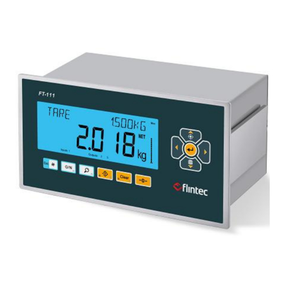
Flintec FT-111 Series Technical Manual (146 pages)
Weighing Terminal
Brand:
Flintec
| Category:
Accessories
| Size: 5.76 MB
Table of Contents
Table of Contents
2
1 Safety Instructions
6
2 Declaration of Conformity
7
3 Introduction
8
Overview
8
Variants
8
Specifications
9
The Front View and Key Functions
14
Display
14
Key Pad
16
Passwords
17
Key Lock
17
4 Installation
18
Recommendations
18
Environment
18
Cabling
18
Electrical Connection
18
Location of the Peripheral Connections
19
Cleaning
19
Disposal
19
Housing
20
Mechanical Installation
20
Electrical Connections
21
Analogue Load Cell Connection (Only FT-111)
21
Digital Load Cell Connection (Only FT-111 D)
22
RS232C Serial Port
23
RS485 Serial Port
24
RS422 Serial Port
25
Ethernet TCP/IP
26
Profibus DP
27
Profinet
27
Canopn
28
Ethernet/Ip
29
Ethercat
30
CC-Link
30
Powerlink
31
CC-Link IE
31
USB Port
32
Installation of Alibi SD Card
32
Installation of SD Card
33
Digital Inputs
34
Digital Outputs
34
Analogue Connection
35
Power Source Connection and Grounding
35
5 D) Functions
36
Basic Functions
36
Advanced Functions
38
Alibi Memory
40
6 Programming and Calibration
42
Entering to the Programming and Calibration
42
Quick Access Parameter Blocks Used Frequently
43
Exit from Programming
43
Programming and Parameters
44
Calibration
68
Linearity Correction
68
Zero and Span Adjustments
69
Ecal Electronic Calibration
70
Gravity Adjustment
71
Calibration Coefficients
71
7 Digital Load Cell (DLC)
72
Addressing Digital Load Cells
72
8 Digital Inputs and Outputs
74
Digital Inputs
75
Digital Outputs
76
9 Serial Data Outputs
86
Continuous Data Output
86
Continuous Data Formats
87
Fast Continuous Data Output
90
Print Mode
90
EPL Format
91
BSI Data Structure for Dialog with PC
92
BSI-Base Commands
94
10 Optional Communication
97
Analogue Output
97
Modbus RTU and TCP/IP
98
Modbus Command Table
99
Ethernet TCP/IP
105
Ethernet Parameters
105
Profibus DP
106
Data Format
106
GSD Configuration
107
Profibus DP Data Structure
107
Profinet
108
Data Format
109
Profinet Parameters
109
GSDML Configuration
109
Profinet Data Structure
110
Canopen
111
Data Format
111
EDS Configuration
112
Canopen Date Structure
112
Ethernet/Ip
113
Data Format
114
Ethernet/Ip Parameters
114
EDS Configuration
114
Ethernet/Ip Data Structure
115
Ethercat
116
Data Format
116
ESI Configuration
117
Ethercat Data Structure
117
CC-Link
118
Data Format
118
CC-Link Configuration
119
CC-Link Data Structure
119
Powerlink
120
Data Format
121
XDD Configuration
121
Powerlink Data Structure
121
CC-Link IE Field
122
Data Format
122
CC-Link IE Configuration
123
CC-Link IE Data Structure
123
11 Appendix 1: Data Structure Profibus, Profinet, Ethernet/Ip, Ethercat, CC-Link, Powerlink, CC-Link IE
124
11 Appendix 1: Data Structure Profibus, Profinet, Ethernet/Ip
133
12 Appendix 2: Data Structure Canopen
133
13 Sealing of Approved Scale
142
14 Trouble Shooting
143
Advertisement
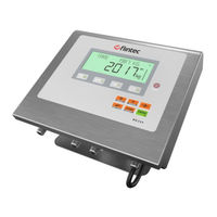
Flintec FT-111 Series User Manual (137 pages)
Weighing Indicator
Brand:
Flintec
| Category:
Measuring Instruments
| Size: 5.81 MB
Table of Contents
Table of Contents
2
Safety Instructions
5
Introduction
6
Overview
6
Specifications
6
Housing
10
Mounting Kits
10
The Front View and Key Functions
12
Display
12
Keypad
14
Installation
15
Recommendations
15
Environment
15
Mechanical Installation Recommendations
15
Cabling Recommendations
15
Electrical Connection Recommendations
16
Installation Steps
17
Step 1: Preliminary Preparations
17
Step 2: Mechanical Installation
17
Step 3: Open the Housing / Close the Housing
19
Step 4A: Analogue Load Cell Connection
19
Step 4B: Digital Load Cell Connection (Only FT-111 D)
20
Step 5: RS 232C Serial Ports
21
Step 6: RS 485 Serial Port
22
Step 7: Ethernet TCP/IP
22
Step 8: USB Port
23
Step 9: Alibi Memory
24
Step 10: Optional Board Installation
24
Step 11: Power Source Connection and Grounding
24
Step 12: Scale Setup and Calibration
25
Step 13: Use
25
Installation of Optional Boards
26
Cleaning
27
Disposal
27
Functions
28
Basic Functions
28
Advanced Functions
29
Backup and Restore (with SD Card)
31
Setup, Backup and Restore Via Indface2X Software
32
Firmware Upgrade
32
Copying the Weighing-Related Data from SD Card to a PC
32
Digital Inputs and Outputs
33
Digital Inputs
34
Digital Outputs
34
RS232 and RS485 Data Outputs
39
Continuous Data Output
39
Fast Continuous Data Output
40
Print Mode
40
EPL Format
42
BSI Data Structure for Dialog with PC
42
Fieldbus Interface
42
Programming and Calibration
43
Alphanumeric Entry for Headers and Footers
43
Entering to the Programming and Calibration
44
Quick Access Parameter Blocks Used Frequently
44
Exit from Programming
44
Programming and Parameters
45
[1-- INTERFACE] Interface Block
46
[2-- CONFIGURATIO] Configuration Block
56
[3-- APPLICATION] Application Block
58
[5-- SCALE] Scale Block
61
[6-- CALB / ADJUST] Calibration and Adjustment Block
64
[8-- METROLOGY] Metrology Block
65
[9-- DIAGNOSTIC] Diagnostic Block
66
Calibration
68
Linearity Correction
68
Zero and Span Adjustments
69
Ecal Electronic Calibration
70
Gravity Adjustment
71
Calibration Coefficients
71
Digital Load Cells (DLC)
72
Addressing of Digital Load Cells
72
Sealing of Approved Scale
75
Optional Boards
76
Digital Inputs and Outputs
76
Alibi Memory
77
Installation of Alibi SD Card
77
Activating Alibi Memory
78
How Is the Data Recorded into the Alibi Memory
78
Recall Data from Alibi Memory
78
Installation of SD Card
80
BSI Protocol to Interface with PC and PLC
81
BSI-Base Commands
82
Continuous Data Formats
88
Analogue Output
91
Analogue Output Connection
91
Modbus RTU
93
Modbus RTU Data Structure
93
Ethernet TCP/IP
99
Ethernet Parameters
99
Modbus TCP Data Structure
100
Profibus DP
101
Electrical Connection
101
Data Format
102
GSD Configuration
102
Profibus DP Data Structure
102
Profinet
103
Electrical Connection
104
Data Format
104
Profinet Parameters
105
GSDML Configuration
105
Profinet Data Structure
106
Ethernet/Ip
107
Electrical Connection
108
Data Format
109
Ethernet/Ip Parameters
109
EDS Configuration
109
Ethernet/Ip Data Structure
110
Ethercat
111
Electrical Connection
112
Data Format
112
ESI Configuration
113
Ethercat Data Structure
113
CC-Link
114
Electrical Connection
114
Data Format
115
CC-Link Configuration
115
4CC-Link Data Structure
115
Powerlink
116
Electrical Connection
117
Data Format
117
3XDD Configuration
118
Powerlink Data Structure
118
Appendix 1 Data Structure Profibus, Profinet, Ethernet/Ip, Ethercat, CC-Link, Powerlink
119
Appendix 2: Data Structure Canopen
126
Error Codes
135
Advertisement
Related Products
Flintec FT-111D Series
Flintec FT-111 D
Flintec FT-111 IO
Flintec FT-111 D IO
Flintec FT-111 AN
Flintec FT-111 D AN
Flintec FT-111 PB
Flintec FT-111 D PB
Flintec FT-111 PN
Flintec FT-111 D PN
Flintec Categories
Control Unit
Amplifier
Media Converter
Measuring Instruments
Monitor
More Flintec Manuals
Login
Sign In
OR
Sign in with Facebook
Sign in with Google
Upload manual
Upload from disk
Upload from URL