Table of Contents
Advertisement
Advertisement
Table of Contents

Related Manuals for Flintec FT-111 Series


Summary of Contents for Flintec FT-111 Series
- Page 1 FT-111(D) Panel Weighing Terminal Technical Manual...
-
Page 2: Table Of Contents
Table of Contents: Safety Instructions ..............5 Declaration of Conformity ............6 Introduction ................7 Overview ............................. 7 Variants ............................... 7 Specifications ............................8 The Front View and Key Functions ....................13 Display ...............................13 Key Pad .............................15 Passwords ............................16 Key lock .............................16 Passwords ............................16 Installation ................ - Page 3 Linearity Correction ...........................67 Zero and Span Adjustments ......................68 eCal Electronic Calibration .......................69 Gravity adjustment ..........................70 Calibration coefficients ........................70 Digital Load Cell (DLC) ............71 Addressing Digital Load cells ......................71 Digital inputs and outputs ............73 Digital inputs ............................74 Digital outputs ............................75 Serial Data Outputs ...............
- Page 4 Appendix 1: Data Structure Profibus, Profinet, EtherNET/IP, EtherCAT, CC-Link, Powerlink, CC-Link IE ........123 Appendix 2: Data Structure CANopen ........ 132 Sealing of Approved Scale ..........141 Trouble Shooting ..............142 FT-111(D) Panel Weighing Indicator, Technical Manual, Rev.1.0.0, May 2019 Page 3 of 146...
- Page 5 FLINTEC GmbH reserves the right to revise this manual and alter its content without notification at any time. Neither FLINTEC GmbH nor its affiliates shall be liable to the purchaser of this product or third parties for damages, losses, costs, or expenses incurred by purchaser or third parties as a result of: accident, misuse, or abuse of this product or unauthorized modifications, repairs, or alterations to this product, or failure to strictly comply with FLINTEC GmbH operating and maintenance instructions.
-
Page 6: Safety Instructions
FOR FUTURE REFERENCE. DO NOT ALLOW UNTRAINED PERSONNEL TO OPERATE, CLEAN, INSPECT, MAINTAIN, SERVICE, OR TAMPER WITH THIS EQUIPMENT. ALWAYS DISCONNECT THIS EQUIPMENT FROM THE POWER SOURCE BEFORE CLEANING OR PERFORMING MAINTENANCE. CALL FLINTEC ENGINEERING FOR PARTS, INFORMATION, AND SERVICE. WARNING! ONLY PERMIT QUALIFIED PERSONNEL TO SERVICE THIS EQUIPMENT. -
Page 7: Declaration Of Conformity
ECLARATION OF ONFORMITY EU-Konformitätserklärung EU-Declaration of Conformity Monat/Jahr: month/year: 07/2019 Hersteller: Manufacturer: Flintec GmbH Anschrift: Address: Bemannsbruch 9 D-74909 Meckesheim Deutschland / Germany Produktbezeichnung: Product name: FT-11x / FT 11x panel Wägeterminal / Weighing Terminal Nr. der Bauartzulassung: No. 0200-NAWI-04810, FORCE Certification No oft the EC type-examination certificate: Nichtselbsttätige Waage (NSW) -
Page 8: Introduction
NTRODUCTION 3.1 Overview FT-111 Weighing indicator is economic and powerful state-of-the-art indicator for industrial weighing applications like basic weighing, labelling system control with digital outputs, fieldbus interfacing etc. It’s set memory 500 item record size which each item has 5 pieces limit values gives big advantage in operation. Digital inputs and outputs of the instrument can be programmed as a Remote IO on the fieldbus. -
Page 9: Specifications
3.3 Specifications Analogue Load cell (only FT-111) A/D converter type 24-bit Delta-Sigma ratio metric with integral analog and digital filters Conversion rate Up to 1600 measurement values per second 0,4 μV/e approved; 0.05 μV/d non approved. Input sensitivity Analog input range -5 mV to +19 mV Internal resolution up to 16 000 000... - Page 10 Memory Set Memory to save limit values at your industrial weighing. Application memories Memory size is 500 item records Alibi memory (optional) 99 999 records Communication Connectable with PC, PLC, Printer, Remote display, EPL printer etc. Isolation Galvanically isolated. Baud rate 1200 to 57600 programmable Data Length 7 or 8 bits;...
- Page 11 Profibus DPV1 opional)) Data rate Up to 12000 kbit/s with automatic baud rate detection GSD file Generic GSD-file provided Depending on physical media Topology RS-485: segmented line topology without stubs Shielded twisted pair cable Installations Line length depending on physical media and transmission speed Max.
- Page 12 EtherNet/IP opional)) Data rate 10 Mbit/s or 100 Mbit/s, full duplex EDS file Generic EDS-file provided DLR (Device Level Available Ring) DHCP or manual IP assign over EtherX PC Software or by keys in programming TCP/IP settings mode. Device identity customization Topology Line, Bus, Star or Tree topology depending on physical media Switched Ethernet transmission with shielded twisted pair cables and RJ-45...
- Page 13 XDD file XDD-file provided Ring redundancy Available Topology 100% free choice of star, tree, ring or daisy chain Switched Ethernet transmission with shielded twisted pair cables and RJ-45 Installation connectors. Isolation Galvanically isolated bus electronics Response speed Min. 4 ms response delay after read/write commands Digital inputs and outputs of the instrument can be programmed independently as Remote IO a Remote IO’s of PLC to control them over fieldbus.
-
Page 14: The Front View And Key Functions
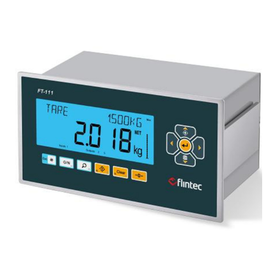
3.4 The Front View and Key Functions Figure 3.1 – Front view of FT-111 Display The bright and wide angle LCD display of the FT-111 instruments is shown below. The meanings of the announcement symbols on the display are: 6-digit 22 mm height big weighing display with sign 16-digit 8 mm height alphanumeric information display High resolution digit separator. - Page 15 Bar graph Indicates the range of the scale at multi range and multi interval operations. g, kg, t, lb, klb, N, kN units are located on the right of the display. Announces the activated inputs and outputs. Announces the instrument is at repair status or call service. Announces the weight value is in the center of zero range.
-
Page 16: Key Pad
3.5 Key Pad The keys and the key functions of FT-111 in usage are: Programmable Function key This programmable key is set for your easy usage in your application. Page 56, 37, Escape Press this key to exit from any entry or from any block at programming. Temporary gross weight indication Press the key to read the gross weight temporary until pressing the key. -
Page 17: Passwords
3.6 Passwords RELATED PARAMETERS: Sub-block 26- . Key lo FT-111 has capability to lock the keys to avoid unauthorized interfere. The key(s) which would be locked are programmed in the setup at sub-block 34- . Key lock password default is 11. Lock the keys: 1. -
Page 18: Installation
NSTALLATION PRECAUTION: Read this section carefully before installation of the instrument. Applying the recommendations in this section will increase your system reliability and its long-term performance. 4.1 Recommendations Environment The weighing indicator should be placed in an area which is clean, not getting direct sun light if possible, having a temperature between -15 ºC and +55 ºC and humidity not exceeding 80% non-condensing. -
Page 19: Location Of The Peripheral Connections
Location of the Peripheral Connections The electrical terminals are located on the rear of the instrument as shown in the picture below. Calib. switch Ethernet Power RS232 RS485 Load Cell TCP/IP card RS422 Figure 4.2 – The rear view of the instrument and terminal names. 4.2 Cleaning Warning: Disconnect the instrument from power source before start cleaning for your safety. -
Page 20: Housing
4.4 Housing 112,5 mm 205mm ( 8.07" ) ( 4.43" ) 91 mm 108 mm ( 3.58" ) ( 4.25" ) Front view Side view 186 mm ( 7.32" ) 92 mm ( 3.62" ) Panel cut sizes 4.5 Mechanical Installation Cut the panel of the cabinet to install the Insert the instrument to the cut on the panel after instrument.. -
Page 21: Electrical Connections
4.6 Electrical Connections Analogue Load Cell Connection (Only FT-111) To avoid damages, the load cell wiring should be made carefully before energizing the instrument. Load cell connection schematics are in Figure The same polarity sense and excitation pins of the load cell connector should be short circuited for 4-wire installation. -
Page 22: Digital Load Cell Connection (Only Ft-111 D)
Digital Load Cell Connection (Only FT-111 D) The digital load cell wiring should be made carefully before energizing to avoid FT-111 D and load cells from damages. The instrument cable between the instrument and junction box must be shielded and convenient for high speed RS485 interfacing. -
Page 23: Rs232C Serial Port
RS232C Serial Port FT-111 weighing indicator has RS232C serial port which is galvanically isolated from other circuitry to increase the EMC immunity. The usage of this serial port and its specifications are described in the Table 4-3 and its pin configuration is shown in Table 4-4. -
Page 24: Rs485 Serial Port
RS485 Serial Port The usage of this galvanically isolated serial port and its specifications are described in the Table 4-5 and its pin configuration is shown in Table 4-6. Refer to page 45 to configure RS485 serial port and page 85 for details on data formats. -
Page 25: Rs422 Serial Port
RS422 Serial Port The usage of this full duplex serial port and specifications are shown in the Table 4-7 and its pin configuration is shown in Table 4-8. Refer to page 46 to configure the serial port and page 85 for details on data formats. Remember 120-ohm line termination resistors should be installed both ends of the RS422 line. -
Page 26: Ethernet Tcp/Ip
……… 31 Figure 4.11 – The second RS485 port usage of RS422 port (half duplex). Ethernet TCP/IP The usage of the Ethernet port on the main PCB and its data formats are shown in the Table 4-9 and its pin configuration is shown in Table 4-10. -
Page 27: Profibus Dp
The PC connection cabling is done via cross cable as shown below. IP address blocks and gateway address of FT-111 and PC should be the same in cross connection. Figure 4.13 - PC connection with cross cable Important note: Disconnect ndface2x set up PC software before Ethernet interfacing. Profibus DP Figure 4.14 - PLC Connection PROFIBUS Connector pin configuration (DB9F) -
Page 28: Canopn
The HUB connection cabling will be a direct connection as shown below: Figure 4.16 - HUB connection The PC connection cabling will be done via cross cable as shown below. IP address blocks and gateway address of weighing indicator and PC should be the same in cross connection. Figure 4.17 - Cross PC connection CANopn CANopen connection is done with four wire as indicated below in Figure 4.18. -
Page 29: Ethernet/Ip
EtherNET/IP Figure 4.19 – PLC Connection EtherNet/IP Connector pin configuration (RJ45) Signal Description Differential Ethernet transmit data + TX− Differential Ethernet transmit data − Differential Ethernet receive data + RX− Differential Ethernet receive data − Not used Terminated Not used Terminated Not used Terminated... -
Page 30: Ethercat
EtherCAT Figure 4.22 – PLC Connection EtherCAT Connector pin configuration (RJ45) Signal Description Differential Ethernet transmit data + TX− Differential Ethernet transmit data − Differential Ethernet receive data + RX− Differential Ethernet receive data − Not used Terminated Not used Terminated Not used Terminated... -
Page 31: Powerlink
Powerlink Figure 4.25 - PLC Connection Powerlink Connector pin configuration (RJ45) Signal Description Differential Ethernet transmit data + TX− Differential Ethernet transmit data − Differential Ethernet receive data + RX− Differential Ethernet receive data − Not used Terminated Not used Terminated Not used Terminated... -
Page 32: Usb Port
Alibi memory requires the Alibi SD card at the SD1 card slot on the bottom of the main board as shown in the pictures below. If you install the alibi memory SD card, order Alibi SD pack from Flintec or dealer. -
Page 33: Installation Of Sd Card
Installation of SD Card Some features of the FT-111 requires SD card which its slot is located on the rear of the instrument like Modbus RTU / TCP. These SD cards should be ordered for your usage. Inserting the SD card 1. -
Page 34: Digital Inputs
Digital Inputs: FT-111 digital inputs are programmable for zeroing, taring, clear, print, key lock, dynamic weighing start/reset, basic peak, hold and as a fieldbus Remote input at basic weighing. Inputs connection diagram is shown in Figure 4.29. Inputs are 12 .. 28 VDC, 10 mA Figure 4.29 - Connection diagram of digital inputs Digital Outputs: FT-111 instrument digital outputs can be programmable as a free setpoint, as a control output or as a remote output at basic... -
Page 35: Analogue Connection
Analogue Connection Figure 4.31 Analogue connections are done as indicated below in and Figure 4.32. Figure 4.31 - Voltage output connections Figure 4.32 - Current output connections Power Source Connection and Grounding Connect DC power supply of FT-111 to a noise proof power line due to the very low measuring signal level. The quality of the power line and DC power supply will determine the accuracy and the safety of your measuring system. -
Page 36: D) Functions
5 FT-111(D) F UNCTIONS 5.1 Basic Functions Zeroing Zeroing corrects the drifts of the unloaded scale from the zero point. 1. Unload the scale. 2. Press key. 3. Centre of zero appears symbol on the display. 4. Check the center of zero sign on the left of the display. If it doesn´t appear, press the key once more for correct zeroing. - Page 37 The printout format can be selected from parameter 161. Flintec PC software is used to program EPL printout data and download in to the instrument for free programming the data output or for label printing including barcode.
-
Page 38: Advanced Functions
5.2 Advanced Functions Programmable key key can be programmable to fit the instrument in to your application and for your easy it. The programmable functions are unit change, dynamic start/reset, basic peak, hold etc. Refer to sub-block 24-, page 56 to see the availabilities. High resolution If you press key, the weight value is displayed 10 times higher resolution until pressing the same key again. - Page 39 Date and Time RELATED PARAMETERS: Parameters 251, 252 and 253. Date format of the country 1. Enter the programming and go to parameter 251, page 56. 2. Press keys to select date format: DMY ( DD.MM.YYYY ), MDY ( MM.DD.YYYYY) or YMD ( YYYY.MM.DD ) and press key to confirm.
-
Page 40: Alibi Memory
Next verification date The instrument warns the operator on the following verification or calibration date, if date is entered. The warning is disappeared after pressing key until switch on the instrument again. 5.3 Alibi Memory RELATED PARAMETERS: Main block 8--. You can fulfill your weight data recording obligations with the alibi memory in certified operation without having paper archive. - Page 41 Search with Alibi record number: 1. Press key after selecting NUM in parameter 813. 2. Press numerical keys to enter alibi number in the printout data and press key. You may navigate in the alibi memory with keys after entering alibi number. 3.
-
Page 42: Programming And Calibration
ROGRAMMING AND ALIBRATION You will find the programming and calibration procedure of FT-111 weighing indicator in this section. The arrow on navigation keys indicates the function of the keys in programming menu. The basic meanings of these keys are; Navigation Exit from any Go to Next block. -
Page 43: Quick Access Parameter Blocks Used Frequently
6.2 Quick Access Parameter Blocks used Frequently The instrument has fast access feature to the frequently adjusted parameters for easy usage or service. As described in the previous section, if you press the keys below for more than 2 seconds at main block [1—INTERFACE ] , you will access to the parameter blocks fast. -
Page 44: Programming And Parameters
6.4 Programming and Parameters FT-111 weighing indicator is programmed under the seven main blocks in the programming menu which are serial interface, configuration, application, scale, calibration, metrology and diagnostic. Main blocks in the programming menu are displayed like [1-- INTERFACE ] and sub-blocks are displayed like [11- RS232C ]. - Page 45 Modbus RTU High-Low format MBLH Modbus RTU Low-High format Press key to select output format different than Flintec continuous data format while the selection is CONT in the information display. Available functions are seen on the weight display after pressing key sequentially.
- Page 46 Modbus RTU High-Low format MBLH Modbus RTU Low-High format Press key to select output format different than Flintec continuous data format while the selection is CONT in the information display. Available functions are seen on the weight display after pressing key sequentially.
- Page 47 Modbus RTU High-Low format MBLH Modbus RTU Low-High format Press key to select output format different than Flintec continuous data format while the selection is CONT in the information display. Available functions are seen on the weight display after pressing key sequentially.
- Page 48 High speed continuous data output BSI format for PC, PLC interface Press key to select output format different than Flintec continuous data format while the selection is CONT in the information display. Available functions are seen on the weight display after pressing key sequentially.
- Page 49 Modbus TCP High-Low format MBLH Modbus TCP Low-High format Press key to select output format different than Flintec continuous data format while the selection is CONT in the information display. Available functions are seen on the weight display after pressing key sequentially.
- Page 50 153 ADDRESS 01 ] Address of the port 00 …. 255. 00 means data format without address. 154 SUB MASK : 000 ] Subnet mask address. Default is 255.255.255.000 155 GATEWAY 253 ] Gateway address. Default is 192.168.016.253 156 LOCAL P1 502 ] Local port 1.
- Page 51 Printing with key LOCK Print interlock. Only one time printout, if weight change is more than 10 division. AUTO Auto print, if the gross load is bigger than MIN WEIGHT and stable. Unload and load the scale for next printing. LOAD Autoprint if W>MIN WEIGHT and weight change is more than 10d.
- Page 52 177 LF AFTE +4 ] Line feed after printout. + = Forward , - = Backward NO,1,2….9 : Line feed quantity after data. Example: -2 means 2 line feed backward. 178 FORM FE NO ] Form feed. Disable Enable 179 LEFT SP Space from left of the label.
- Page 53 PROFIBUS CONFIGURATION (Only FT-111 PB) Press key or key again to enter this menu. 19- PROFIBUS Press key to go to beginning of the sub-block or press key to go to the next main-block. 191 FORMAT : INTG ] Data format of the Profibus INTG Signed 32 bit integer, no decimal point implied.
- Page 54 ETHERNET/IP CONFIGURATION (Only FT-111 EI) Press key or key again to enter this menu. 19- ETHERNET IP Press key to go to beginning of the sub-block or press key to go to the next main-block. 191 FORMAT : INTG ] Data format of the EtherNet/IP INTG Signed 32 bit integer, no decimal point...
- Page 55 POWERLINK CONFIGURATION (Only FT-111 PL) Press key or key again to enter this menu. 19- POWERLINK Press key to go to beginning of the sub-block or press key to go to the next main-block. 191 FORMAT : INTG ] Data format of the Powerlink INTG Signed 32 bit integer, no decimal point implied.
- Page 56 KEYSOU YES ] Key sound Disable Enable 214 REFRESH : Display refresh rate : 1...9 times/sec INFORMATION DISPLAY 22- INFO DISPLAY Press key or key again to enter this menu. Or press key to go to the next sub-block. 221 TIME D+T ] Information data on the right of the alphanumeric display.
- Page 57 235 FILTER MEDI ] Adaptive digital filter. Disable. Fastest weighing; but the most sensitive to environmental vibrations. Very low filtering Low filter MEDI Medium filter HIGH High filter VHIG Very high filter. Slowest and the most stable weighing. LANGUA ENG ] User language.
- Page 58 [ 3-- APPLICATION ] Application Block APPLICATION RELATED PARAMETERS MAIN BLOCK Press key sequentially to access this main block, or press key or key to enter configuration parameters, 3-- APPLICATION or press key to go to the next block, or press key to exit from programming.
- Page 59 347 G/N USE ] G/N key locking Not locked LOCK Locked 348 HIGH USE ] High resolution key locking Not locked LOCK Locked 349 TARE USE ] Tare key locking Not locked LOCK Locked 34A CLEAR USE ] Clear key locking Not locked LOCK Locked...
- Page 60 DIGITAL OUTPUTS (appears if option installed) 36- DIG OUTPUTS Press key or key again to enter this menu. Or press key to go to the next sub-block. Page 75, 361 OUT 1 NO ] Digital output 1 Disable S AIN Absolute Indicated weight S IND Indicated weight...
- Page 61 [ 5-- SCALE ] Scale Block This blocks are related with the measurement related parameters which are described the usage of the scale. The most important parameter is 511 which limit the usage of the parameters in main blocks 5, 6 and 8. The selections of this parameter are;...
- Page 62 Page 35 [ 514 ZEROING 50% ] M Zeroing range with key. Disable. ± 2% ± 3% ± 20% ± 50% Page 35 [ 515 AZTRACK 0.5d ] M Automatic zero tracking. Disable. 0.3d ± 0,3d 0.5d ± 0,5d ± 1d ±...
- Page 63 [ 523 MAX Scale capacity Max and division (d) MAX1/d1 Enter scale capacity and division after press key. MAX2/d2 Capacities and divisions of MR and MI scales are MAX3/d3 entered as Max1, d1, Max2, d2, Max3, d3. [ 524 OVER 9d ] M Limit of Indication Over indication after Max...
- Page 64 [ 6-- CALB / ADJUST ] Calibration and Adjustment Block SCALE ZERO AND SPAN SETTING MAIN BLOCK Press key sequentially to access this main block, 6-- CALIB / ADJUST or press key or key to enter configuration parameters, or press key to go to the next block, or press key to exit from programming.
- Page 65 [ 8-- METROLOGY ] Metrology Block METROLOGY MAIN BLOCK Press key sequentially to access this main block, or press key or key to enter configuration 8-- METROLOGY parameters, or press key to go to the next block, or press key to exit from programming. ALIBI MEMORY Press key or...
- Page 66 [ 9-- DIAGNOSTIC ] Diagnostic Block DIAGNOSTIC MAIN BLOCK Press key sequentially to access this main block, 9-- DIAGNOSTIC or press key or key to enter configuration parameters, or press key to go to the next block, or press key to exit from programming. HARDWARE TESTING 91- HARDWARETEST Press...
- Page 67 971 INSTRUMENT XX.XX 972 OPTION XX.XX 973 UPGRADE Firmware upgrade Call Flintec service or dealer to upgrade. 974 DLC BOARD XX.XX (only FT-111 D) DEFAULTS LOADING Press key or key again to enter this menu.
-
Page 68: Calibration
A minimum test load requirement is 20% of scale capacity for accurate calibration. FLINTEC recommends test load between 50% to 75% of the capacity. Place the test weight on the scale. -
Page 69: Zero And Span Adjustments
A minimum test load requirement is 20% of scale capacity for accurate calibration. FLINTEC recommends test load between 50% to 75% of the capacity. 3. Place the test weights on the scale. -
Page 70: Ecal Electronic Calibration
eCal Electronic Calibration IMPORTANT NOTE: The eCal electronic calibration is based on the zero adjustment by entering the dead load value or automatic zero adjustment and span adjustment by entering the load cell data. WARNING : If the primary unit is no kg, the selected unit should be saved by exit from set-up and then perform e-Cal. -
Page 71: Gravity Adjustment
Gravity adjustment WARNING: This parameter should ONLY be used at the scale that will be initially verified in two stages by gravity adjustment in legal metrologic applications. The gravity acceleration values of the place of the calibration and of the place of the usage are entered in this parameter. -
Page 72: Digital Load Cell (Dlc)
(DLC) IGITAL 7.1 Addressing Digital Load cells IMPORTANT NOTE: You can connect all RC3D to the terminal and address them later. The following diagram shows the recommended load cell addressing principle. Remember, if pair shift adjustment is selected, 1 and 2, 3 and 4 etc. will be sectional pairs. Pair 1 Pair 2 Pair 5... - Page 73 Automatic Shift Adjustment IMPORTANT NOTE: This adjustment must be performed before calibration. Load the scale few times before performing automatic shift adjustment. Small mismatches in mechanical and electronic gain of the load sensing paths can cause the same test weight to produce slightly different readings, depending on the location of the test weight on the scale.
-
Page 74: Digital Inputs And Outputs
IGITAL INPUTS AND OUTPUTS APPLICATION: Digital inputs are used to control the instrument and the digital outputs can be used to control gates, valves etc. or to produce alarm. Setpoint outputs can be updated by actual displayed weight or when the load is stable. RELATED PARAMETERS: Sub-blocks 35- and 36-. -
Page 75: Digital Inputs
8.1 Digital inputs Digital inputs can be used instead of pressing keys for taring, zeroing, clear tare, transfer data etc. as seen below. Basic Peak on the display and Hold display are the additional input functions. Key functions via inputs Zeroing, Taring, Clear, Print The key functions are executed via digital inputs. -
Page 76: Digital Outputs
8.2 Digital outputs Digital outputs can be programmable as free setpoints which can be programmed for different functions as seen below. The output (s) can be produced as threshold or window additional to the well-known basic output at free programmable setpoints. S AIN Free setpoint of absolute indicated weight The status of the digital output changes with comparing the set point value and absolute indicated weight value as seen below. - Page 77 VIN-LOW Window, active low Output goes to low if absolute indicated weight is between setpoint high and setpoint low. S IND Free setpoint of indicated weight The digital output is activated with comparing the set point value and indicated weight value as seen below.
- Page 78 THR-LOW Threshold, active low Output goes to low if indicated weight is heavier than setpoint high. Returns the high if the weight is less than setpoint low. VIN-HI Window, active high Output goes to high if indicated weight is between setpoint high and setpoint low. VIN-LOW Window, active low Output goes to low if indicated weight is between setpoint high and setpoint low.
- Page 79 S ANE Free setpoint of absolute net weight The digital output is activated with comparing the set point value and absolute net weight value as seen below. As an example, if SP1 = 100 kg or = 100 kg = 150 kg. HIGH BAS-HI Basic, active high Output is high if absolute net weight is heavier...
- Page 80 S NET Free setpoint of net weight The digital output is activated with comparing the set point value and net weight value as seen below. As an example, if SP1 = 100 kg or = 100 kg = 150 kg HIGH = -200kg or = -200kg...
- Page 81 THR-LOW Threshold, active low Output goes to low if net weight is heavier than setpoint high. Returns the high if the weight is less than setpoint low. VIN-HI Window, active high Output goes to high if net weight is between setpoint high and setpoint low.
- Page 82 S GRO Free setpoint of gross weight The digital output is activated with comparing the set point and weight at gross weight indication as seen below. As an example, if SP1 = 100 kg or = 100 kg = 150 kg. HIGH BAS-HI Basic, active high Output is high if gross weight is heavier than...
- Page 83 SPC2 Control mode-2 The digital outputs are activated as seen below, if setpoints are set up to Control mode-2 and their values are entered consequently from setpoint 1 to the setpoint N how much needed. Digital outputs which are not used at this mode can be programmed freely to any other function. For example if SP5 is not needed to control, it can be programmed to the zero range to produce empty signal.
- Page 84 ZR I Zero range of the indicated weight The digital output is activated if the absolute indicated weight value is in the zero range. Refer to parameter 366 to enter zero range value. ZR G Zero range of the indicated weight The digital output is activated if the gross weight value is in the zero range.
- Page 85 Entry the limit values 1. Press the key. 2. The setpoint 1 value appears as shown on the display [ SP 1 1250 kg ]. 3. Press key to increase or press key to decrease the blanking digit and press key to select a digit.
-
Page 86: Serial Data Outputs
ERIAL UTPUTS FT-111 weighing indicator has RS232, RS485, RS422, USB and Ethernet interfaces. In this section, you will find the data structure of different type of the data outputs via these serial ports. If, you transmit ASCII codes of P(print), Z(zero), T(tare) or C(clear) letters to the serial port of FT-111; it will act like the related key is pressed. 9.1 Continuous Data Output Continuous data output of the instrument is transmitted in the following data structure. -
Page 87: Continuous Data Formats
Continuous Data Formats RELATED PARAMETERS: Parameters 111, 121, 131, 141 and 151. Continuous data output can be programmed to some common formats besides Flintec continuous formats. To select one of the described formats below press the key sequentially. Press key to go to the next parameter. - Page 88 ® Description STX Sign Indicated weight Unit ♥ ☻ Example ® Toledo Description STX A Indicated weight Tare weight CR LF ♠ ☻ Example ® SysTec Description Status Indicated weight Unit Example Description Indicated weight Unit Example Function Description Line Feed ( 0A hex ) Z = Centre of zero, O = Over cap, U = Under cap,...
- Page 89 ® Rinstrum Description Sign Indicated weight ☻ ♥ Example ® Avery E1205 Description STX Indicated weight Unit ☻ ♥ Example ® Baster Description Indicated Weight Example Character number Description Indicated Weight Unit Example-1 Example-2 Function Description These eight characters are a string containing the current weight not Indicated Weight including the decimal point.
-
Page 90: Fast Continuous Data Output
You can send the data in multiple line formats as seen in the label given below by pressing key. The data output including can be programmed with printer parameters. The multiline data output can be programmed for 16 byte narrow printers and for others. Format for 16 character printer : Flintec Flintec www.flintec.com www.flintec.com Meckesheim, Germany... -
Page 91: Epl Format
The EPL format of the data output in Print mode is selected to print the label data in graphical format EPL. You can design your label in EPL format by using the printer label design software and Flintec software as describe below. -
Page 92: Bsi Data Structure For Dialog With Pc
If you will integrate FT-111 into your computer or if you will interface FT-111 with your PLC which do not have any fieldbus interface, using BSI commands will help you to expand your system with additional FLINTEC scale without having to change your application programs. - Page 93 BSI-Base Commands and Responses: Read all weight data immediately Read Gross weight value immediately Clear the tare Read voltage value of DC power supply Read current weight (indicated) value immediately Read the current stable weight value Load set point values Read set point values Read Status Tare...
-
Page 94: Bsi-Base Commands
BSI-Base Commands Read all weight data Command : [ADR][A] Response : [ADR][A][STATUS][SIGN][NET W][SIGN][TARE W][SIGN][GROSS W] Example : Command : 01A Response : 01AS+000123.4+000111.1+000234.5 01AD+000123.4+000111.1+000234.5 01AO ( ADC out error ) Comments The response is net, tare and gross weight values or error status. All weight data is transmitted immediately after receiving the command. - Page 95 Load set points Command : [ADR][Q][SET No][L][SIGN][SP VALUE] Response : [ADR][Q][STATUS] Example : Command : 01Q01L+000123.4 Response : 01QA (123.4 loaded to SP1) 01QN (Could not loaded) 01QX (Decimal point of SP VALUE is mismatch) Comments SP Number is 2 byte ASCII char. Use 01 for SP1, 02 for SP2 and 03 for SP3. SP VALUE data is 8-byte ASCII char with dot and non-significant zeros on the left.
- Page 96 Read digital outputs Command [ADR][V] Response [ADR][V][STATUS][Outputs] Example : Command : 01V Response : 01VA03 (Output 2 and Output 1 are active) 01VA96 (Output 8,5,3,2 are active) 01VAFF (All 8 outputs are active) 01VN (Could not read outputs) Comments Data length change according to number of digital outputs. Outputs are implemented to ASCII char of 4-bit.
-
Page 97: Optional Communication
10 O PTIONAL OMMUNICATION 10.1 Analogue Output IMPORTANT NOTE The analogue output cable should be shielded. Connect the shield to the protective earth as described in the installation section. FT-111 has analogue output, which is programmable to 4 – 20 mA, 0 – 20 mA, 0 – 5 V or 0 – 10 V. Analog output is automatically adjusted to the weighing range after the calibration. -
Page 98: Modbus Rtu And Tcp/Ip
10.2 Modbus RTU and TCP/IP IMPORTANT NOTE: Modbus RTU and Modbus TCP interfaces require Modbus SD card at the SD2 card slot on the rear of the instrument. FT-111 controller supports a Modbus RTU interface over RS485, RS422 or RS232C serial port. This interface can be programmable to High-Low or Low-High for different type of PLC’s. -
Page 99: Modbus Command Table
Modbus Command Table; Address R/W Word Command Definition 40001 Actual weight (Net if the indication is in Net, Peak value or Hold value) 40003 Tare weight 40005 Gross weight Definition 0 – Dynamic is inactive 1 – Dyn weight is calculating 0 –... - Page 100 Keylock enable Keylock disable Dynamic Start Dynamic Reset 14-23 Not used Basic peak enable Basic peak disable Hold enable Hold disable None Command is processing… 40027 Commands status Command is successfully. Command failed. 40029 Reserve Definition Input-1 0 – Passive 40041 Status of Inputs Input-2...
- Page 101 ± 20% ± 50% Disable ± 0,3d ± 0,5d 40135 Auto Zero Tracking ± 1d ± 2d ± 3d 40137 Tare Multi tare Tare only at gross ± 0,3d ± 0,5d ± 1d Stability 40139 ± 2d Detection Range ± 3d ±...
- Page 102 9 division more than Max. 2% more than Max. 5% more than Max. Subtractive tare 40177 Tare type Additive tare 40179 Maximum tare Refer to par. [526] page 62 Description (Gram (Kilogram) (Ton) 40181 Secondary unit (Libre) No unit (without unit) (Newton) (Kilonewton) (Kilolibre)
- Page 103 Scale unstable - Wait until scale become stable - Check grounding wiring The Calibration switch is not ‘On’ position. - Check the calibration DIP switch. 40197 Reserve Voltage of The value is indicated with 0.1 VDC increment for DC 40207 power supply variant.
- Page 104 Below you will find some command samples; Description Request weight data 01,03,00,00,00,02,C4,0B Answer of request weight 01,03,04,00,01,86,A0,38,4A (weight value is 100000 ) Request status data 01,03,00,07,00,02,75,CA Taring 01,10,00,18,00,02,04,00,00,00,02,72,C4 Request tare data 01,03,00,02,00,02,65,CB Answer of request tare 01,03,04,00,00,27,10,E0,0F (tare value is 10000 ) Zero Command 01,10,00,18,00,02,04,00,00,00,01,32,C5 Request Calibration Status...
-
Page 105: Ethernet Tcp/Ip
Ethernet parameters can be adjusted by keys in programming mode. Refer to parameter block [ 15- ]. Additionally, Ethernet parameters set up is done by Indface2x PC software over Local Network Area or by Flintec´s set up PC software. Both softwares are available on www.flintec.com... -
Page 106: Profibus Dp
93.75 kbps, 187.5 kbps, 500 kbps, 1.5 Mbps, 3 Mbps, 6 Mbps and 12 Mbps. No ‘baud rate’ instance exists. Refer to Profibus parameters, sub-block 19-, GSD file is available on internet www.flintec.com. There are two LEDs near the Profibus connector;... -
Page 107: Gsd Configuration
GSD Configuration Profibus data consist of 2 x Input-2 words and 2 x Output-2 words. The GSD file is available in on internet www.flintec.com.. GSD configuration for PLC programmers is shown in Figure 10.1. Figure 10.1 - GSD Configuration GSD Configuration... -
Page 108: Profinet
The Profinet interface is 100Mbit and full duplex. GSDML file for two port Profinet is available in on internet www.flintec.com. There are 4 announcement LEDs on the instrument to indicate the interface status as seen below. The meanings of these LED’s are;... -
Page 109: Data Format
Profinet parameters can be adjusted by keys in programming mode. Refer to parameter block [ 19- ]. Additionally, Profinet parameters set up is done by Indface2x PC software over Local Network Area or by Flintec set up PC software. Both softwares are available on www.flintec.com. -
Page 110: Profinet Data Structure
Figure 10.3 - GSDML Configuration GSDML Configuration Description Input 2 word_1 Dword (FT-111 Output to PLC Input) Input 2 word_2 Dword (FT-111 Output to PLC Input) Output 2 word_1 Dword (PLC Output to FT-111 Input) Output 2 word_2 Dword (PLC Output to FT-111 Input) Profinet Data Structure For the Data Structure for Profinet see Appendix 1, page 123 FT-111(D) Panel Weighing Indicator, Technical Manual, Rev.1.0.0, May 2019... -
Page 111: Canopen
After setting related parameters you can communicate with FT-111 via CANopen network. EDS file is available in on internet www.flintec.com. Automatically detected and supported baud rates are 10 kbps, 50 kbps, 100 kbps, 125 kbps, 250 kbps, 500 kbps, 800 kbps, 1 Mbps, Autobaud (default). -
Page 112: Eds Configuration
EDS Configuration CANopen data structures consist of TxPDO ( 64 bit ) and RxPDO ( 64 bit ). EDS configuration for PLC programmers is Figure 10.4 shown in Figure 10.4 - EDS Configuration EDS Configuration Description TxPDO 1 (4 words Unsigned Long (FT-111 Output to PLC Input) RxPDO 1 (4 words) Unsigned Long (PLC Output to FT-111 Input) -
Page 113: Ethernet/Ip
You may change the port, if there is any malfunction on port in usage. The EtherNet/IP interface supports 10/100Mbit, full or half duplex operation. EDS file for two port EtherNet/IP is available on internet www.flintec.com There are 4 announcement LEDs on the instrument to indicate the interface status as seen below. -
Page 114: Data Format
EtherNet/IP parameters can be adjusted by keys in programming mode. Refer to parameter block [ 19- ]. Additionally, EtherNet/IP parameters set up are done by EtherX PC software over Local Network Area or by Flintec set up PC software. Both softwares are available in CD which is supplied together with the instrument. -
Page 115: Ethernet/Ip Data Structure
Figure 10.6 – Configuration of module properties with EDS file Data Length Description Input 2 words Dword (FT-111 Output to PLC Input) Input 2 words Dword (FT-111 Output to PLC Input Output 2 words Dword (PLC Output to FT-111 Input) Output 2 words Dword (PLC Output to FT-111 Input EtherNet/IP Data Structure... -
Page 116: Ethercat
2. Star connection. If you connect the instrument to your PLC via hub switch, you can use P1 port on the instrument. ESI file for two port EtherCAT is available in on internet www.flintec.com. There are 4 announcement LEDs on the instrument to indicate the interface status as seen below. The meanings of these LED’s are;... -
Page 117: Esi Configuration
ESI Configuration EtherCAT data structures consist of 2 pcs Input-2 words and 2 pcs Output-2 words. ESI configuration for PLC programmers is shown in Figure 10.7. Figure 10.7 – Configuration of module properties for Beckhoff Input/Output Definition Description SubIndex 001 Dword (FT-111Output to PLC Input) DI TxPDO-Map SubIndex 002... -
Page 118: Cc-Link
10.10 CC-Link After setting related parameters you can communicate with FT-111 via CC-Link network. Supported CC-Link version is v1.10 and baud rates are 156 kbps (default), 625 kbps, 2,5 Mbps, 5 Mbps and 10 Mbps. There are 2 LED’s near the CC-Link connector which are; (A) RUN LED (B) ERR LED CC-Link interface... -
Page 119: Cc-Link Configuration
CC-Link Configuration The weighing indicator has occupied one station area on CC-Link network and station type of weighing indicator must be programmed as ‘Remote device station’ in the PLC software. CC-Link configuration for PLC programmers is shown in Figure 10.8. Figure 10.8 –... -
Page 120: Powerlink
You may change the port, if there is any malfunction on port in usage. The Powerlink interface is 100Mbit and half duplex. Powerlink is available in on internet www.flintec.com. There are 4 announcement LEDs on the instrument to indicate the interface status as seen below. The meanings of these LED’s are;... -
Page 121: Data Format
LINK/Activity LED LED State Description No link. Green Link, no traffic. Green, flashing Link and traffic. Data Format Data format of weight value can be programmable for Floating point (IEEE 754) or Integer. Refer to parameter [ 191 ]. XDD Configuration Powerlink data structures consist of 2 pcs Input-2 words and 2 pcs Output-2 words. -
Page 122: Cc-Link Ie Field
10.12 CC-Link IE Field After setting related parameters you can communicate with FT-111 via CC-Link network. There are 2 LED’s near the CC-Link connector which are; (A) NS/RUN LED (B) AS/ERROR LED Link/Activity LED (port 1) Link/Activity LED (port 2) P1 interface (port 1) P2 interface (port 2) (A) NS/RUN LED... -
Page 123: Cc-Link Ie Configuration
CC-Link IE Configuration The weighing indicator has occupied one station area on CC-Link network and station type of weighing indicator must be programmed as ‘Remote device station’ in the PLC software. CC-Link configuration for PLC programmers is shown in Figure 10.8. –... -
Page 124: Appendix 1: Data Structure Profibus, Profinet, Ethernet/Ip, Ethercat, Cc-Link, Powerlink, Cc-Link Ie
11 A 1: D PPENDIX TRUCTURE ROFIBUS ROFINET NET/IP, E CAT, CC-L , CC-L THER THER OWERLINK FT-111 Output to PLC Input Bitwise of a Dword: B31 B30 B29 B28 B27 B26 B25 B24 B23 B22 B21 B20 B19 B18 B17 B16 Dword (Only read) - Page 125 00101 Last print value 00110 Not used 01010 01011 CN (Label number) 01100 Not used 01110 SetPoint-1 (High) 01111 SetPoint-2 (High) 10000 SetPoint-3 (High) 10001 SetPoint-4 (High) 10010 SetPoint-5 (High) 10011 Not used 10100 10101 SetPoint-1 Low 10110 Only available for Threshold and SetPoint-2 Low Window feature.
- Page 126 ALL Status ( always 32 bit integer ) Dword (input) descriptions when read command is ‘ALL Status’. Refer to 2 Dword of PLC Output to FT-111 Input. Bit Number Dword (input) Description None No decimal point None Decimal point is X.X None Place of decimal point Decimal point is X.XX...
- Page 127 Calibration Status (always 32 bit integer) Dword (input) descriptions when read command is ‘Calibration Status’. Refer to 2 Dword of PLC Output to FT-111 Input Bit Number Dword (input) Description B31 … B11 Not in use No Error The Calibration DIP switch is not ‘On’ position. - Check the calibration DIP switch.
- Page 128 PLC Output to FT-111 Input Bitwise of a Dword: B31 B30 B29 B28 B27 B26 B25 B24 B23 B22 B21 B20 B19 B18 B17 B16 Dword (R/W) B15 B14 B13 B12 B11 B10 Dword Next Dword defines the usage of this Dword. (OUTPUT) (RWr0, RWr1...
- Page 129 11000 SetPoint-4 Low 11001 SetPoint-5 Low 11010 Not used 11110 Use the Expanded Command list 11111 (Refer to Table 11-3) 00000 Actual weight (if the indication is in Net) 00001 Gross weight 00010 Tare weight 00011 ALL Status (Refer to Table 11-1) 00100 Table 11-2 Calibration Status (Refer to...
- Page 130 Expanded Command List Dword (Input) is the data receiving from PLC and the “B23 … B16” bits describe below. Here 1 Bit No Description Commands Voltage of power supply 00000000 The value is indicated with 0.1 VDC increment for DC variant. Load cell millivolt value (Only FT-111 ) 00000001...
- Page 131 ± 2d ± 3d ± 4d Disable (1) (2) 01000110 Stability Time Refer to par. [517] page 61 (1) (2) 01000111 Unit No unit Single range 2 x Multi Range (1) (2) 01001000 Range 3 x Multi Range 2 x Multi Interval 3 x Multi Interval (1) (2) 01001001...
- Page 132 Programming steps of frequent used commands: Reading a weight value: 1. Check the B12…B15 bits of ‘FT-111 Output to PLC Input 2 Dword’. 2. If there is not any error, read the weight value (gross, net or tare). Zero Calibration procedure: 1.
-
Page 133: Appendix 2: Data Structure Canopen
12 A 2: D PPENDIX TRUCTURE OPEN FT-111 Output to PLC Input Bitwise of a Dword: B63 B62 B61 B60 B59 B58 B57 B56 B55 B54 B53 B52 B51 B50 B49 B48 Unsigned B47 B46 B45 B44 B43 B42 B41 B40 B39 B38 B37 B36 B35 B34 B33 B32 Long (Only B31 B30 B29 B28 B27 B26 B25 B24 B23 B22 B21 B20 B19 B18 B17 B16... - Page 134 00010 Tare weight 00011 ALL Status (Refer to Table 12-1) 00100 Table 12-2 Calibration Status (Refer to 00101 Last print value 00110 Not used 01010 01011 CN (Label number) 01100 Not used 01110 01111 SetPoint-1 (High) 10000 SetPoint-2 (High) 10001 SetPoint-3 (High) SetPoint-4 (High) 10010...
- Page 135 ALL Status (always 32 bit integer) Low Dword of TXPDO 1(T_UL1) descriptions when read command is ‘ALL Status’. Refer to RxPDO 1(R_UL1) of PLC Output to FT-111 Input. Bit Number Low Dword of TxPDO 1(T_UL1) Description None No decimal point None Decimal point is X.X None...
- Page 136 Calibration Status ( always 32 bit integer ) Low Dword of TXPDO 1(T_UL1) descriptions when read command is ‘Calibration Status’. Refer to RxPDO 1(R_UL1) of PLC Output to FT-111 Input. Bit Number Low Dword of TxPDO 1(T_UL1) Description B31 … B11 Not in use No Error The Calibration DIP switch is not ‘On’...
- Page 137 PLC Output to FT-111 Input Bitwise of a Dword: B63 B62 B61 B60 B59 B58 B57 B56 B55 B54 B53 B52 B51 B50 B49 B48 B47 B46 B45 B44 B43 B42 B41 B40 B39 B38 B37 B36 B35 B34 B33 B32 Unsigned Long (R/W)
- Page 138 Not used 10100 10101 SetPoint-1 Low 10110 SetPoint-2 Low Only available for Threshold and Window feature. 10111 SetPoint-3 Low Refer to sub-block 36-, page 59 11000 to see the availabilities. SetPoint-4 Low 11001 SetPoint-5 Low 11010 Not used 11110 Use the Expanded Command list 11111 ( Refer to Table 12-3 ) 00000...
- Page 139 Expanded Command List The “B48…B55” bits in RxPDO describes below. Bit No Description Commands Voltage of power supply 00000000 The value is indicated with 0.1 VDC increment. Load cell millivolt value (Only FT-111 ) 00000001 Millivolt of active scale is indicated with 0.01 mV increment.
- Page 140 ± 3d ± 4d Disable (1) (2) 01000110 Stability Time Refer to par. [517] page 61 (1) (2) 01000111 Unit No unit Single range 2 x Multi Range (1) (2) 01001000 Range 3 x Multi Range 2 x Multi Interval 3 x Multi Interval (1) (2) 01001001...
- Page 141 Programming steps of frequent used commands: Reading a weight value: 1. Check the B47…B44 bits of TxPDO 1 (T_UL1). 2. If there is not any error, read the weight value ( gross, net or tare ). Zero Calibration procedure: 1. Check the Bit-0 of Calibration Status. it should be '1'(set) to start adjustment. 2.
-
Page 142: Sealing Of Approved Scale
13 S EALING OF PPROVED CALE Sealing of Load cell connector Sealing of Calibration switch Alibi SD card sealing FT-111(D) Panel Weighing Indicator, Technical Manual, Rev.1.0.0, May 2019 Page 141 of 146... -
Page 143: Trouble Shooting
14 T ROUBLE HOOTING FT-111 weighing indicator had been designed as a very reliable and virtually error free instrument. However, if there is an error occurs, do not attempt to repair the equipment before understanding what caused the error. Note the problems you have with your instrument and the error messages shown on the display. - Page 144 - Check Alibi SD card. installed. - Change mainboard. Alibi SD card is not supplied from E41 ALIBI FAULT - Install Flintec Alibi SD card. FLINTEC. Alibi memory serial number error. - Format the alibi memory SD E42 NEW ALIBI The new alibi SD card is installed.
- Page 145 - Check the DLC and S/N. The address and S/N of the load E84 SN NOT MATCH - Reenergize the indicator. DLC yy cell do not match. - Readdress the DLC. - Check the DLC connection (RS-485 & E85 DLC TIMEOUT Communication time out Power supply) hardware.
- Page 146 FT-111(D) Panel Weighing Indicator, Technical Manual, Rev.1.0.0, May 2019 Page 145 of 146...
Need help?
Do you have a question about the FT-111 Series and is the answer not in the manual?
Questions and answers