Table of Contents
Advertisement
Quick Links
Advertisement
Table of Contents

Subscribe to Our Youtube Channel
Related Manuals for Flintec DAD143 Series


Summary of Contents for Flintec DAD143 Series
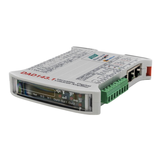
- Page 1 DAD143 User Manual DAD143.x Weighing Indicator User Manual...
-
Page 2: Table Of Contents
Table of Content Introduction ..................................6 Disclaimer ..................................... 6 Safety Instructions ..................................7 Specifications .................................. 8 ....................... 9 Housing & Terminals .................................. 9 Terminals Load Cell Connection ............................. 9 Load Cell Connection ................................. 9 Terminals Power Supply ................................. 10 Terminals Service Port RS 232 .............................. 10 Ethernet Based Ports ................................ - Page 3 Setup via PC / PLC - Command Overview - ......................31 Special Commands of DAD143.x Overview ........................34 8.1.1 AT Auto Transmit (for service port RS 232 connection, only) .................... 34 8.1.2 AT Auto Transmit (for PLC connection) ............................. 34 8.1.3 LE Last Error List (only for RS 232 connection) ........................
- Page 4 9.6.4 GS Get ADC Sample Value ................................ 48 9.6.5 ........................48 9.6.6 OF Output Format for Data String GW ..........................49 9.6.7 GA Get Triggered Average Value ............................49 9.6.8 GH Get Hold Value ..................................50 9.6.9 TH Trigger Hold Value ................................. 50 9.6.10 GM Get Peak Value ..................................
- Page 5 10.1 Access to metrological data and weighing range adjustment ................... 61 10.2 Protection of the metrological data and the scale calibration ................... 61 Calibration and Calibration Sequence........................62 Firmware Update Program ............................63 12.1 FU Firmware Update ................................63 12.2 FD Reset to Factory Default Settings ..........................
-
Page 6: Introduction
Flintec reserves the right to revise this manual and alter its content without notification at any time. Neither Flintec nor its affiliates shall be liable to the purchaser of this product or third parties for damages, losses, costs, or expenses incurred by purchaser or third parties as a result of: accident, misuse, or abuse of this product or unauthorized modifications, repairs, or alterations to this product, or failure to strictly comply with Flintec operating and maintenance instructions. -
Page 7: Safety Instructions
ALWAYS DISCONNECT this equipment from the power source before cleaning or performing maintenance. CALL Flintec for parts, information, and service. WARNING: Only permit qualified personnel to service this equipment. Exercise care when making checks, tests and adjustments that must be made with power on. Failing to observe these precautions can result in bodily harm. -
Page 8: Specifications
2 Specifications DAD 143.x Specifications Accuracy class Test certificate according OIML R76 EU Type approved for 10000 intervals AD converter Delta-Sigma, ± 24 bit Analog input range ±15 mV bipolar (± 3 mV/V @ 5 VDC excitation) 0.2 μV/e (legal for trade); 0.05 μV/d (non legal for trade) Minimum input sensitivity Linearity <... -
Page 9: Housing & Terminals
3 Hardware, Wiring and Housing & Terminals Terminals of the DAD 143.x Scale information for ‘legal for trade’ use Terminals Load Cell Connection DAD 143.x Load cell Function input Pin no. + Exc + Excitation for load cell + Sen + Sense for load cell + Inp + Signal of load cell... -
Page 10: Terminals Power Supply
Terminals Power Supply DAD 143.1 Power in Function Pin no. Power supply +12..24 V DC Power supply +12..24 V DC Common ground / 0 V DC Common ground / 0 V DC Shld. Chassis ground Depending on the grounding concept of the plant/scale, terminal 20 or 21 has to be connected to terminal 22. Terminal 4 (shld load cell) and 22 (Ground chassis) are internal connected. -
Page 11: Led Indicators Terminal 27
LED Indicators Terminal 27 Activity Link of Port 1/2 Colour State Description Protocol firmware running On or flashing Service/maintenance firmware running in various modes No error System Failure Flashing, 1Hz DCP signal service is initiated via the bus System error No error Bus Failure Flashing, 2Hz... -
Page 12: Logic Inputs & Outputs
Logic Inputs & Outputs The DAD143.x offers 2 isolated logic inputs and 3 isolated logic outputs The 2 inputs can e.g. get the function to act as the ZERO or TARE button, see chapter 9.8.1. The 3 outputs act as switches for setpoints with hysteresis, switch behavior etc. Several reference values such as net weight, peak weight or average can be used, see chapter 9.9.3. -
Page 13: Communications And Getting Started
4 Communications and Getting started Service Port Communicating with the digital device DAD 143.x is carried out via serial service port RS 232. The data format is the familiar 8/N/1 structure (8 data bits, no parity, 1 stop bit). Available baud rates of RS 232 port are as follows: 9600, 19200, 38400, 57600, 115200, 230400 and 460800 baud. -
Page 14: Getting Started Via Ethernet Based Port, E.g. Use Profinet Viewer
Profinet is DHCP protocol. • A Windows demo program, Profinet Viewer, for testing the Profinet IO functionality can be downloaded under www.flintec.com see screenshot below. Figure: Screenshot of the Program Profinet Viewer ver. 1.1.0.0 . Important: Make sure your computer is in the same range of IP-addresses as DAD143.x, the gateway address is set correctly, In some cases, MS Windows may block the communication between DAD143.x and the Viewer over... -
Page 15: Menu Structure For Keybord Setup / Inspection
5 Menu Structure for Keybord Setup / Inspection ProfiNet IO DAD 143.x User Manual Profinet Rev.1.1.1 March 2023 Page 15 of 95... -
Page 16: Setup Via Front Panel Keyboard
6 Setup Via Front Panel Keyboard Keyboard Buttons This is the ZERO button. This button can be used for zeroing in scale status This is the TARE button. This button can be used for taring the scale in status The two UP/DOWN buttons will be used for setup via the menu. Use of Keyboard Buttons Press the UP or DOWN button for more than 3 seconds to enter the setup menu of front panel. -
Page 17: Menu 1 System Zero
Menu 1 System Zero Remark: Activate a new calibration with 1x Power OFF & ON ! ZERO setup (Menu 1.1 to 1.4) TAC protected see chapter 9.2.1 Automatic Zero Tracking - Enable / Disable (command ZT) Setting range Disabled @ 00000, no ZERO Tracking Enabled @ 00001 or higher (max 00255) Setting 00001 sets a zero tracking range of ±0.5d Setting 00002 up to 00255 sets a zero track range of... -
Page 18: Menu 2 System Span
Menu 2 System Span Remark: Activate a new calibration with 1x Power OFF & ON ! SPAN setup (Menu 2.1 to 2.4) TAC protected see chapter 10.2.1 Set SPAN Calibration value (command CG) - Set display value equivalent to calibration weight or to mV/V value derived from load cell(s) test data. -
Page 19: Menu 3 Display
Menu 3 Display Remark: Activate a new calibration with 1x Power OFF & ON ! Display setup (Menu 3.1 to 3.4) TAC protected see chapter 9.2.1 Display limits - Overrange / Underrange (commands CMn/CI) 3.1.o1 Display overrange limit CM1 (maximum value +999999) (CM1) Use the UP/DOWN &... -
Page 20: Menu 4 Filter & Motion Detection
Menu 4 Filter & Motion Detection Remark: Activate a new setup with 1x Power OFF & ON ! Digital filter & No Motion setup (Menu 4.1 to 4.4) Low pass filter cut off frequency (command FL) - Settings: 0 - 8 with UP/DOWN buttons 4.1.x Cut off frequency: IIR mode... -
Page 21: Menu 5 Analog Output
Menu 5 Analog Output Remark: Activate a new setup with 1x Power OFF & ON ! Analog output setup (Menu 5.1 to 5.5) Weight value for minimum analog output (command AL) - Set the weight value which corresponds to minimum output Examples Minimum 0kg or with 600kg preload 0kg = 4mA - setting 00000... -
Page 22: Menu 6 Logic Inputs
Menu 6 Logic Inputs Remark: Activate a new setup with 1x Power OFF & ON ! Logic input setup (Menu 6.0 to 6.1) Logic Input "0" n=0) 6.0.x Functions (x = choose one from 00 to 18 with 'up'/'down' buttons) 00 - Input "0"... -
Page 23: Menu 7 Logic Outputs
Menu 7 Logic Outputs Remark: Activate a new setup with 1x Power OFF & ON ! Logic output setup (Menu 7.0 to 7.2) Logic Output "0" 7.0.1 Setpoint "0" 7.0.1.1 Setup of the Setpoint value n=0) Permitted values +/- 999 999 7.0.1.2 Setup the Polarity (switch logic) ON or OFF n=0) - Page 24 6.10 Menu 8 Data Communication Remark: Activate a new setup with 1x Power OFF & ON ! Data Communication setup (Menu 8.1 to 8.9) Baud Rate for Service Port RS 232 (use the UP/DOWN buttons) (command BR) 9600 Baud 19200 Baud 38400 Baud 57600 Baud 115200 Baud...
- Page 25 Menu 8 Data Communication / Continuation Data Communication setup (Menu 8.6 to 8.9) Gateway Address, depending on protocol* (use the UP/DOWN buttons) 8.6.y ProfiNet (factory default), for INSPECTION via front panel, only: 8.6.1 Setting 000192 8.6.2 Setting 000168 8.6.3 Setting 000001 8.6.4 Setting...
-
Page 26: Factory Default Via Front Panel
6.11 Factory Default via Front Panel While Power ON the DAD 143, press both buttons UP & DOWN simultaneously for 2 or 3 seconds for setting the device to factory default. Note: All settings will be deleted proceeding a factory default! 6.12 Error Codes - shown in the Front Panel Display Zero key is not enabled (chapter 7.3, menu 1.1) -
Page 27: Examples Of Calibration
7 Examples of calibration Example 1 Calibration procedure using weights 3 Leg tank or silo fitted with 3 load cells of 1000kg; load cell signal @ 1000kg = 2 mV/V. Dead load of tank / silo is 600kg. Live range is 1 500kg, step size is 0.5kg. It is assumed that the load cell system is connected to the DAD 143.x and the power is on. - Page 28 g The last point for this example are the settings of over/under range. Go to Menu 3.1 (over/under range) by using the UP/DOWN and ZERO keys. Press ZERO key again for setup over range (3.1.o) or additional with UP key under range (3.1.U). The display shows in both cases 099999.9.
-
Page 29: Example 2
Example 2 mV/V sensitivity 3 Leg tank or silo fitted with 3 load cells of 1000kg; load cell signal @ 1000kg = 2 mV/V. Dead load of tank / silo is 600kg. Live range is 1500 kg, step size is 0.5kg. It is assumed that the load cell system is connected to the DAD 143.x and the power is on. - Page 30 f Go to Menu 2.3. by using the UP/DOWN and ZERO keys. The display shows 00.000mV/V. The load cells signal @ 3000kg is e.g. 2.0123mV/V ((signal #1 + signal #2 + signal #3) / 3). By using the UP/DOWN and TARE keys you have to setup each number of the 6-digit display to 02.0123.
-
Page 31: Setup Via Pc / Plc - Command Overview
8 Setup via PC / PLC - Command Overview - Command Short description Parameter value Page Get/set analog output action (base) 0 through 10 Communication: Device Address 0...255 Absolute gain calibration ± 33000 Get/set analog high -999999 to 999999 0 to 15 Get/set analog low -999999 to 999999 Analog Output Mode Current / Voltage... - Page 32 Logic input: for each Input Status 0 or 1 Logic output: for each Output Status 0 or 1 Device information: Identify Device Status None Device information: Identify Firmware Version None Last Error occurred in DAD143.x, showing a code between 0 and 15 None Calibration: Define Multi-interval (0) or Multi-range (1) 0 or 1...
- Page 33 values 2 exp 7 = 128) 0...7 Save the Setup Data (FL, NR, NT, AD, BR, DX) to the EEPROM None Initial Zero Setting ON/OFF 0 or 1 Zero Mode 0 or 1 Non Volatile Zero Value ON/OFF @ power OFF 0 or 1 Calibration: Zero Range 0...999999...
-
Page 34: Special Commands Of Dad143.X Overview
Special Commands of DAD143.x Overview Command Short description Parameter value Commands For Application Filling (In / Out) These commands are part of the seperate manuals • FT1 - firmware type 1 (dose in) or • FT3 - firmware type 3 (dose out). Dose Info Start cycle Abort cycle... -
Page 35: Le Last Error List (Only For Rs 232 Connection)
Any other value will set the output to 0.0 . Note: Setting AT 1 will transmit e.g. the net weight in the format: • If the net weight is negative, then a '-' (minus) will be sent, else a ' ' (space) will be sent. •... -
Page 36: Setup Via Pc / Plc - Command Descriptions
9 Setup via PC / PLC - Command Descriptions For better clarity, all commands are divided into groups as described on the following pages. Each command For each command, the ProfiNet Index / Sub-Index are displayed in brakets [Index 0xNNNN Sub 0xSS] explained in the communication profile . -
Page 37: Sr Reset Dad143.X Firmware
9.1.4 Reset DAD143.x Firmware 9.1.4.1 [Index 0x2007 Sub 0x04] Master (PC / SPS) sends Slave (DAD143.x) responds SR DAD143.x. It has the same functionality as power OFF and ON again. 9.1.5 Read Serial Number 9.1.5.1 [Index 0x2900 Sub 0x0C] Issuing the RS command will return the current serial number in the format S+12345678. Master (PC / SPS) sends Slave (DAD143.x) responds Meaning... -
Page 38: Ci Set Minimum Output Value
Zero point, gain and decimal point position were saved in the EEPROM; the calibration counter (TAC) is increased automatically by +1. 9.2.2 Value [CM1: Index 0x2300 Sub 0x07] [CM2: Sub 0x0E] [CM3: Sub 0x0F] point in multi range applications). Permitted values are from 1 to 999 999. Master (PC / PLC) sends Slave (DAD143.x) responds Meaning... -
Page 39: Ds Set Display Step Size
9.2.5 Set Display Step Size [Index 0x2300 Sub 0x0C] This command allows the output to step up or down by a unit other than 1. Permitted values are 1, 2, 5, 10, 20, 50, 100, 200 and 500. Master (PC / PLC) sends Slave (DAD143.x) responds Meaning DS... -
Page 40: Av Show Actual Internal Mv/V Value
9.2.10 AV Show Actual Internal mV/V Value [Index 0x2900 Sub 0x12] Master (PC / PLC) sends Slave (DAD143.x) responds Meaning AV A+02644 mV/V value is 0.2644 mV/V Note: This value is for ro (read only). This means no TAC protection. 9.2.11 ZT Zero Tracking [Index 0x2100 Sub 0x12]... -
Page 41: Tm Tare Mode
9.2.15 TM Tare mode [Index 0x2300 Sub 0x12] This command sets the tare mode. Permitted values are 0 or 1. Master (PC / PLC) sends Slave (DAD 143.X) responds Meaning CE E+00017 (example) Request: TAC counter CE17 CE17 Calibration sequence active TM1... -
Page 42: Ag Absolute Gain Calibration (Ecal)
9.2.20 AG Absolute gain calibration (eCal) [Index 0x2300 Sub 0x01] The command AG is used as absolute gain (or measuring range) for all weight calculations and will setup in mV/V. Permitted values are ± 33 000 (= ± 3.3000 mV/V). Master (PC / PLC) sends Slave (DAD143.x) responds Meaning... -
Page 43: Motion Detection Commands Nr, Nt
Note: Please note, the firmware type selection is locked in the same way as the calibration, that means it must be unlocked with the command "CE n" before the firmware type can be set. Then the FT setting must be saved with the command "CS". -
Page 44: Fl Filter Settings
The digital IIR filter operates as 2 order low pass filter and Gaussian characteristics. The attenuation is 40dB/decade (12 dB/octave). The digital FIR filter works as a low-pass filter with quick response; damping see table mode 1. Factory default: FM = 0 (IIR filter) 9.4.2 FL Filter Settings [Index 0x2100 Sub 0x04]... - Page 45 Mode 1 (FIR filter) Settings / Characteristic UR0 [= 1] UR7 [= 128] 20 dB 40 dB Settling Damping Output Output 3 dB Cut-off Stop damping damping time to in the rate rate frequency band 0.1% stopband --highest- --lowest-- frequency frequency (ms) (Hz)
-
Page 46: Pf Pre-Filter
9.4.3 PF Pre-filter [Index 0x2100 Sub 0x16] Use of the Pre-filter command is recommandet for experts only, get status or set. Note: Special command for internal use of manufactorer or for specialists only. For use, please ask Hauch & Bach ApS or your supplier. 9.4.4 UR Update Rate and Averaging [Index 0x2100 Sub 0x11]... -
Page 47: St Set Tare
9.5.3 ST Set Tare [... see chapter 15.2.7, table bit 3] This command will activate the net weighing function by storing the current weight value as a tare value. Range) and NT (No Motion Time) Master (PC / PLC) sends Slave (DAD143.x) responds Meaning ST... -
Page 48: Ti Averaging Time For Automatic Taring
9.5.7 TI Averaging Time for Automatic Taring [Index 0x2500 Sub 0x07] This command defines the averaging time for the automatic taring. Within this time period the system calculates an averaged tare value. Permitted values are from 0 to 65535. Default setting: TI = 0 ms [= automatic taring disabled] Master (PC / PLC) sends Slave (DAD143.x) responds Meaning... -
Page 49: Of Output Format For Data String Gw
+000100 +001100 Leading Net weight Gross weight First Second Checksum character excluding excluding decimal bitmapped bitmapped signifies the GW decimal point point binary value binary value The bitmapped characters are: First bitmapped Second bitmapped value description value description Not used No motion Output 0 active Zero action performed... -
Page 50: Gh Get Hold Value
9.6.8 Get Hold Value [Index 0x2900 Sub 0x0F] Get the actual weight value, activated by the logic inputs. Master (PC / PLC) sends Slave (DAD143.x) responds Meaning GH H+001.800 Hold value: 1800 d 9.6.9 TH Trigger Hold Value [... see chapter 15.2.7, table bit 6] Saves the weight value of the last GH reading. -
Page 51: Sg Send Gross Value Continuously
9.7.1 SG Send Gross Value continuously Master (PC / PLC) sends Slave (DAD143.x) responds Meaning SG G+001.100 Gross value: 1,100 d 9.7.2 SN Send Net Value continuously Master (PC / PLC) sends Slave (DAD143.x) responds Meaning SN N+001.000 Net value: 1,000 d 9.7.3 Issuing the SW command, which has no parameters, will return continously the net weight, the gross weight, the status and the checksum values, all combined into one single string in the format... -
Page 52: 9.8 Logic Input Functions & Status
9.8 Logic Input Functions & Status 9.8.1 [Index 0x2D00 Sub 0x01 / 0x02] Master (PC / PLC) sends Slave (DAD143.x) responds Meaning AI_1 I1:+00000 Reading Input 1: no function AI_1_10 Setup accepted AI_1 I1:+00010 00 - Input "n" has no function 01 - Input "n"... -
Page 53: Om Control Of The Logic Outputs By The Host Application
Master (PC / PLC) sends Slave (DAD143.x) responds Meaning IO IO:0001 Output 0 is high IO IO:0101 Outputs 0 and 2 are high IO IO:0111 Outputs 0, 1 and 2 are high The status of the outputs can be changed by issuing the IO command with the appropriate 4 digit code e.g. IO 0001 where in this example output 0 will be activated (FET conducting). - Page 54 00 - Gross value 01 - Net value 02 - Peak value (Maximum) 03 - Average value (check weigher) 04 - Hold value 05 - Peak to Peak value 06 - Valley value (Minimum) 07 - Error 4 or 5 9.9.4 Value [Index 0x2600 Sub 0x01 / 0x02 / 0x03]...
-
Page 55: Ht Hold Time For All Setpoints
9.9.6 [Index 0x2680 Sub 0x01 / 0x02 / 0x03] This command is used to setup the switch characteristic of the 3 setpoints S0, S1 and S2. Master (PC / PLC) sends Slave (DAD143.x) responds Meaning P0 P0:+00000 Request: Polarity of setpoint S0 is OFF P0_1... -
Page 56: Dx Operation Mode Half-/Full-Duplex
9.10.3 DX Operation Mode Half-/Full-Duplex The DAD143.x can operate in half or full duplex mode. Master (PC / PLC) sends Slave (DAD143.x) resp. Meaning DX X:001 Request: DX = 1 (full duplex, factory default)) DX 0 Setup: DX = 0 (half duplex) 9.10.4 OP Open Device This command, if sent without parameters, requests the address or device number of the device active on... -
Page 57: 9.11 Analog Output
9.11 Analog Output AA, AH, AL, AM, AR (only in DAD 143.1) The following commands must be saved in EEPROM by command AS. 9.11.1 AA Analog Output Base [Index 0x2100 Sub 0x01] Master (PC / PLC) sends Slave (DAD143.x) responds Meaning AA... -
Page 58: 9.12 Save Calibration And Setup
9.12 Save Calibration and Setup CS, WP, SS, AS, GI, PI The calibration and setup parameters can be divided in 4 groups: • Calibration: CM, DS, DP, CZ, CG, ZT, IZ and FD, etc. saved by command CS • Setup: FL, FM, NR, NT, BR, AD, DX and others, saved by command WP •... -
Page 59: Pi Download An Image File To The Eeprom
9.12.6 PI Download an Image File to the EEPROM Downloads a HEX-INTEL formatted EEPROM image file to the target DAD143.x EEPROM. The image file contains all stored information except the calibration data. Attention: The target DAD143.x must have same firmware type and revision no. as the source DAD143.x. 9.13 Trigger Commands SD, MT, GA, TE, TR, TL, SA When using these commands, e.g. -
Page 60: Te Trigger Edge
9.13.4 TE Trigger Edge [Index 0x2500 Sub 0x02] command can only be used in conjunction with a hardware trigger on the digital input 0. Master (PC / PLC) sends Slave (DAD143.x) responds Meaning TE E:001 Request: TE = 1 (rising edge) TE 0... -
Page 61: 10 Legal For Trade Applications
10 Legal For Trade Applications The weighing indicators of the DAD 14x.y series have type approvals for Class III with 10000 parts according to OIML R76 for NSW (non-automatic weighing instruments) according to the Directive 2014/31/EU. The minimum verification interval value is 0.2μV per increment. With the EU Type Approval, a device of the DAD14x.y series can be used as a legal for trade weighing indicator for single-range and multi-interval scales. -
Page 62: 11 Calibration And Calibration Sequence
11 Calibration and Calibration Sequence The calibration of DAD143.x is only possible after starting a calibration sequence (compare with chapter 8.4). • Command CE: Calibration enable returns the current TAC value • Command CM: Calibrate maximum display sets the max. allowable display value •... -
Page 63: 12 Firmware Update Program
The FU command will transfer a new version of the main firmware from the internal flash disk to the flash memory in the DAD 143.x micro controller and re-start the device. Ask Flintec for the actual PFL program. DAD 143.x User Manual Profinet Rev.1.1.1 March 2023... -
Page 64: Fd Reset To Factory Default Settings
FD command. After this the vital data values can be loaded back into the device. Download the actual version of https://www.flintec.com DAD 143.x User Manual Profinet Rev.1.1.1 March 2023 Page 64 of 95... -
Page 65: Service Commands Overview Profinet
13 Service Commands Overview ProfiNet Command Short description Parameter value Name of station None Show one (of four) MAC address(es) assigned to the DAD 143.x 1..4 Network Address (IP address) aaa.bbb.ccc.ddd Network mask aaa.bbb.ccc.ddd Default gateway address aaa.bbb.ccc.ddd Protocol firmware select 1, 2, 3 or 4 13.1 General System Command... -
Page 66: Ng Network Gateway (Read Only)
13.2.3 NG Network Gateway (Read only) The NG command can show the actual default gateway address currently in use by the DAD 143.x. PC sends DAD 143.x responds Meaning NG G:000.000.000.000 Current default gateway is shown Factory default: 0.0.0.0 Note: The NG setting can also be viewed from the front panel. Use front panel menu 8.6. 13.2.4 DN Device Name (Read only) -
Page 67: 14 Cyclic Data Transfer - Profinet
14 Cyclic Data Transfer - ProfiNet Measuring data and status information from the DAD is sent cyclic to the PLC as a complete data package. Simple commands (Tare, zero, etc) are also sent as cyclic data from the PLC to the DAD. An additional mechanism in the cyclic data transfer allow the PLC to send commands to the DAD and the reply to be sent back to the PLC. -
Page 68: Cmdrddata
14.1.3 CmdRdData When a read command is sent to the DAD through the cyclic data exchange system this variable will hold the data read from the DAD. 14.1.4 Data1 This variable holds a data value specified by the programmer. See 14.2.8 Select1. 14.1.5 Data2 This variable holds a data value specified by the programmer. -
Page 69: Cmdwrdata
14.2.2 CmdWrData When data has to be written to the DAD then the data must be placed in this variable. 14.2.3 Index A variable or parameter in the DAD is addressed by an index and a subindex. Appendix C contain a list of available indexes and subindexes in the DAD 143.x. -
Page 70: 15 Acyclic Data Transfer - Profinet
15 Acyclic Data Transfer - ProfiNet The parameters and variables in the DAD 143.x can also be read and written using acyclic read* / write record* requests. These requests require a single index for addressing the parameters. Appendix C contain a list of all the parameters and variables in the DAD. -
Page 71: Status Code
Out of tare range 16 Appendix A DAD 143.x GSDML File The GSDML file can be down loaded from www.flintec.com A subset of this file is shown below as screen shots from the PROFINET GSD Checker V2.35. Overview DAD 143.x User Manual Profinet Rev.1.1.1 March 2023... - Page 72 Modules Command Module DAD 143.x User Manual Profinet Rev.1.1.1 March 2023 Page 72 of 95...
- Page 73 Modules - DataModule DAD 143.x User Manual Profinet Rev.1.1.1 March 2023 Page 73 of 95...
- Page 74 17 Appendix B Parameter list for the DAD 143.x Index Sub- Acyclic Name Type Attri- Default Meaning Index Index Value 0x2000 0x00 0x0020 Number of entries. 0x06 Number of entries. 0x01 0x0021 Gross weight. REAL32 Get gross weight GG command. 0x02 0x0022 Net weight.
- Page 75 0x2007 0x00 0x00C0 Number of entries. 0x04 Number of entries. 0x01 0x00C1 Not used. Not used. 0x02 0x00C2 Not used. Not used. 0x03 0x00C3 Not used. Not used. 0x04 0x00C4 Software reset. Software reset SR command. Index Sub- Acyclic Name Type Attri- Default...
- Page 76 Index Sub- Acyclic Name Type Attri- Default Meaning Index Index Value 0x2200 0x00 0x0100 Number of entries. 0x17 Number of parameters 0x01 0x0101 Pre-fill mode. PreFill Mode PD1 command. Only for 0x02 0x0102 In-flight correction factor. Inflight Correction PD2 command. 0x03 0x0103 Zero check time.
- Page 77 Index Sub- Acyclic Name Type Attri- Default Meaning Index Index Value 0x2200 0x00 0x0100 Number of entries. 0x17 Number of parameters 0x01 0x0101 Pre-fill mode. PreFill Mode PD1 command. Only for 0x02 0x0102 In-flight correction factor. Inflight Correction PD2 command. 0x03 0x0103 Not used.
- Page 78 Index Sub- Acyclic Name Type Attri- Default Meaning Index Index Value 0x2300 0x00 0x0120 Number of entries. 0x19 Number of calibration parameters. 0x01 0x0121 Absolute gain. 10000 Absolute gain calibrate (TAC protected) AG command. 0x02 0x0122 Absolute zero. Absolute zero calibrate (TAC protected) AZ command.
- Page 79 0x05 0x0165 HoldTime. HoldTime HT command. 0x06 0x0166 TareWindow. TareWindow TW command. 0x07 0x0167 TareTime. TareTime TI command. Index Sub- Acyclic Name Type Attri- Default Meaning Index Index Value 0x2600 0x00 0x0180 Number of entries. 0x03 Number of Set-points 0x01 0x0181 Set-point 1 value.
- Page 80 0x0C 0x020C Serial Number. UI32 Get serial number RS command. 0x0D 0x020D Extended status. UI32 Get qualifier. See cyclic data - Qualifier 0x0E 0x020E Get peak value. REAL32 Get peak value GM command. 0x0F 0x020F Get hold value. REAL32 Get hold value GH command. 0x10 0x0210 Get valley value.
-
Page 81: 18 Instructions For Program
Profinet Viewer ver. 1.1.0.0 18 Instructions for program or higher Note: The Setup of the menus 8.4.y to 8.6.y will be proceeded by your ProfiNet Controller. Via the front panel menus 8.4.y, 8.5.y and 8.6.y you can READ ONLY for inspection the IP address, the network mask and the default gateway address. -
Page 82: Appendix B Parameter List For The Dad 143.X
Connect the DAD143.x via serial port RS232 with your PC, e.g. with a converter cable RS232 to USB. If necessary, check first the baud rate. The required setting is 115200 baud. Below you see the start window of the ProfiNet Viewer (ver. 1.1.0.0. or higher). The ProfiNet communication is not active. - Page 83 window shows the network parameters, which you can READ ONLY, see below. Note: A new delivered DAD143.x is set as factory default to ProfiNet IO, and all 3 network addresses are set to 0.0.0.0. This means, the device was not connected to any ProfiNet Master before. Please see the 1st note of chapter 19 page 82, too.
- Page 84 10. After a few seconds you get the following information of your Network, see below. Note: The reason for this message is that Index 01 shows a device, which has no Station Name and no IP Address. Select the marked Network Index 04 DAD 143.x User Manual Profinet Rev.1.0.0 October 2022 Page 85 of 95...
- Page 85 12. Now you see the found device(s), which are connected via Ethernet based Port 1 or 2: 13. Mark the line Index 01 and set IP Address. DAD 143.x User Manual Profinet Rev.1.0.0 October 2022 Page 86 of 95...
- Page 86 14. In any case you have to set Address and Mask. The Address range, e.g. 192.168.178.xxx, must be adjusted to your network. The you can choose freely. Network Mask set to 255.255.255.0. A Gateway Address is not required. 15. Now set the IP Address. It takes some seconds, and you see the IP Address in line 01: DAD 143.x User Manual Profinet Rev.1.0.0 October 2022 Page 87 of 95...
- Page 87 16. Next step is to set/enter the Station Name. 17. Set the Station Name in this example we choose dad143.1 and press the button OK: DAD 143.x User Manual Profinet Rev.1.0.0 October 2022 Page 88 of 95...
- Page 88 18. The procedure Set the Station Name and IP Address is finished now. 19. Mark Index 01 and press the button OK to start ProfiNet communication. DAD 143.x User Manual Profinet Rev.1.0.0 October 2022 Page 89 of 95...
- Page 89 20. The ProfiNet Viewer was startet and presents the window below: Display Data1 shows the Net weight Display Data2 shows the Tare Weight Scale is in status No Motion (green LED) You can use the buttons Set or Reset Tare, and Set or Reset Zero Out 0, Out 1 and Out 2 shows the status of setpoints.
- Page 90 22. Press button Commands Cyclic for getting access to the Commands Overview see below. The upper window shows the current values in Interger format, and the lower windows shows the current values in hex format. DAD 143.x User Manual Profinet Rev.1.0.0 October 2022 Page 91 of 95...
- Page 91 Additional you see the Main Index and Sub Index. 23. Use Commands Overview for setup commands, here Filter FL see below. Marked are the Cmd Group Filter and Cmd Name Filter Value . Now you can change the value e.g. to 5, then DAD 143.x User Manual Profinet Rev.1.0.0 October 2022 Page 92 of 95...
- Page 92 24. Change Decimal Point setting via button Calibrate Enable see below. 25. Setting of new DP value 2 see below. DAD 143.x User Manual Profinet Rev.1.0.0 October 2022 Page 93 of 95...
- Page 93 26. Press button Save Value (CS) for permanent storing, and the TAC increase by +1 to 66. DAD 143.x User Manual Profinet Rev.1.0.0 October 2022 Page 94 of 95...
- Page 94 27. The DAD 143.x User Manual Profinet Rev.1.0.0 October 2022 Page 95 of 95...
- Page 95 DAD 143.x User Manual Profinet Rev.1.0.0 October 2022 Page 96 of 95...
Need help?
Do you have a question about the DAD143 Series and is the answer not in the manual?
Questions and answers