
Related Manuals for Nexta Tech MCX-M/ONE


Summary of Contents for Nexta Tech MCX-M/ONE
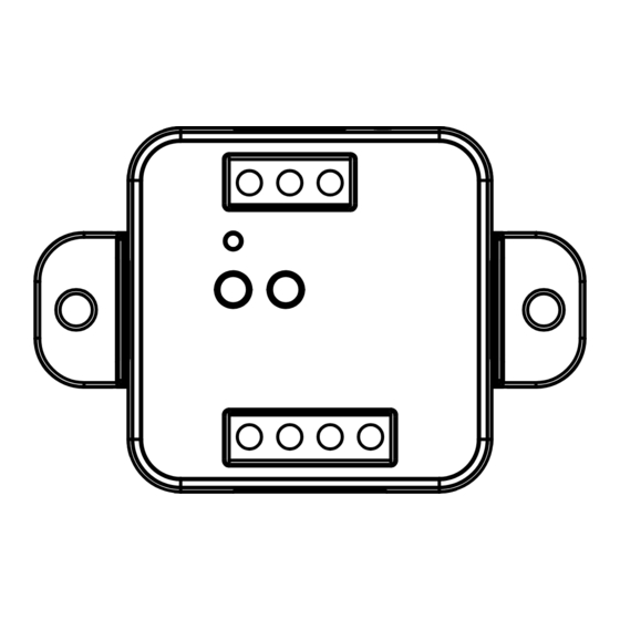
- Page 1 MCX-M/ONE Control unit for 230Vac motors with built-in dip switches. Power supply 230Vac, Max 500W. Integrated 433,92 MHz radio receiver. WiFi connection for OneSmart App.
- Page 2 INDEX 1 - PRODUCT FEATURES 1.1 - TECHNICAL DATA page 3 2 - CONNECTION DIAGRAMS 2.1 - CONNECTION DIAGRAM WITH NEUTRAL FROM CONTROL UNIT page 4 2.2 - CONNECTION DIAGRAM WITH NEUTRAL FROM THE ELCTRICAL SYSTEM page 5 3 - USE OF THE CONTROL UNIT 3.1 - TYPICAL INSTALLATION page 6 3.2 - USE VIA WIRE...
- Page 3 1 - PRODUCT FEATURES 1.1 TECHNICAL DATA Power supply (Input) 230Vac Load type (Output) 230Vac motor with built-in limit switches Max power load (Output) 500W N° of programmable transmitters RF receiver frequency 433,920MHz WI-FI module frequency 2,4GHz (no 5GHz) Protection rating IP20 Working temperature -20°...
-
Page 4: Connection Diagrams
2 - CONNECTION DIAGRAMS RECOMMENDATIONS • Installation must be carried out only by professional technicians in accordance with the applicable electrical and safety regulations. • All connections shall be operated without electrical voltage. • Use proper cables. • Don’t cut the antenna •... - Page 5 2.2 CONNECTION DIAGRAM WITH NEUTRAL FROM THE ELECTRICAL SYSTEM OUT 230V max 500W OP C CL P1 P2 P1 P2 Filar inputs can be set to: - Mono/Double Button, see paragraph 7.3 - Automatic/man-present operation, see paragraph 7.4...
- Page 6 3 - USE OF THE CONTROL UNIT 3.1 TYPICAL INSTALLATION The system can be controlled by a wired push button, radio commands, smartphone App OneSmart or voice commands. The installation can operate with only radio controls or application only. Instead, to use voice commands, at least the App configuration must be completed. NEXTA CONTROL UNIT RADIOTRANSMITTER CONFIGURATION...
- Page 7 3.2 USE VIA WIRE Once connected, the button is already active with Open/Stop/Close function. 3.3 USE VIA RADIO To control the load via radio you must have compatible transmitters and therefore must carry out the association procedure, see paragraph 4. 3.4 USE VIA SMARTPHONE APP ONESMART The configuration procedures described in paragraph 5 above must be followed to control the load by smartphone App.
-
Page 8: Radio Programming
4 - MANAGEMENT WITH REMOTE CONTROL This procedure lets you programme/delete compatible transmitters. 4.1 - RADIO PROGRAMMING This procedure lets you programme compatible multifunctional or generic transmitters. STEP 1 Press the button P1 on the receiver for a short time. The LED comes red on and stays on. - Page 9 4.2 - DELETION OF REMOTE CONTROL These procedures let you delete from the memory transmitters that have already been programmed. STEP 1 Hold the receiver button P1 down (about 8 seconds.) until the LED begins to Flash. ACTION: Hold button P1 down LED: Flashes red DELETION OF SINGLE DELETION OF ALL...
- Page 10 5 - CONTROL WITH APP ONE SMART These procedures allow you to manage the light from your device (example: mobile phone) through the application and to control the system remotely. 5.1 - APP CONNECTION This procedure connects the control unit to the application. It shall be repeated for each control unit on the installation. ATTENTION: an internet-based 2,4GHz Wi-Fi (no 5GHz) network is required for this operation.
- Page 11 5.2 - USE OF THE APP ONE SMART After all the control units have been set up, the installation can be managed by the application. The “Home” menu (1) shows all the associated devices. To send a command to a device, select it. Pressing “Smart”...
- Page 12 6 - CONTROL BY VOICE COMMANDS You can use this procedure to associate a “OneSmart” account with a Google or Alexa account to enable the voice commands. 6.1 - CONNECTION TO “GOOGLE HOME” PROCEDURE WARNING: before proceeding with this procedure, you must have set up the “OneSmart” account, see paragraph 6. 1.
- Page 13 6.2 - CONNECTION TO “AMAZON ALEXA” PROCEDURE WARNING: before proceeding with this procedure, you must have set up the “OneSmart” account, see paragraph 6. 1. Download the App “Amazon Alexa” 2. After starting the application, you will need to create an account Amazon. Complete the procedure.
- Page 14 6.3 - USING VOICE CONTROLS In order to set up voice commands, you must create a scene on OneSmart and then associate it with a Google or Alexa routine by choosing the phrase to pronounce to match the most appropriate action. You must create a scene for each command you want to use with the voice.
- Page 15 6.3c - CREATING A ALEXA ROUTINE 1 - On Alexa application, select the menu (1) 2 - Select “Routines” (2), and then add a new one 3 - Enter the name (3), the phrase you want to pronounce (4), and “add an action” (5) select “Smart Home”, then select “Control scene”.
-
Page 16: Advanced Programs
7 - ADVANCED PROGRAMS 7.1 - CONFIGURATION OF MANEUVER TIMES Default: 60 seconds This procedure is used to set the opening and closing manoeuvre time (maximum time that can be set 180 seconds). STEP 1 Make short pressures of the P2 button. Each time the LED changes colour green/yellow/magenta/ green... - Page 17 7.2 - FUNCTION CUSTOMIZATION OF THE “WIRELESS BUS” GENERIC TRANSMITTER BUTTONS The following procedure allows you to set a custom function to the “wireless bus” family transmitter button. PROCEDURE STEP 1 Press the button P1. The led turns on red. ACTION: Short press of button P1 LED: Turns on red STEP 2...
- Page 18 7.3 - WIRED INPUT SETTING Default: Mono button This procedure lets you select the function of inputs “P1” (terminal 3) and “P2” (terminal 4). WARNING: the connected devices must be buttons. PROCEDURE STEP 1 Make short pressures of the P2 button. Each time the LED changes color: green/yellow/magenta/ green...
- Page 19 7.4 - WIRED INPUT MODE SETTING Default: automatic This procedure allows you to select the mode of operation between: automatic: after pressing the button the automation completes the movement to the limit switch present man: automation moves until the button is pressed PROCEDURE STEP 1 Make short pressures of the P2 button.
- Page 20 7.5 - RESET OF THE CONTROL UNIT This procedure let you take the control unit back to factory settings. ATTENTION: the only parameter that will not be removed will be the association with the ONESMART application. To edit or delete also this parameter, reed the procedure. PROCEDURE STEP 1 Hold the receiver button P1 down (about 4 seconds.) until...
-
Page 21: First Checks
8 - INSIGHTS 8.1 – ISSUES WHEN CONNECTING THE CONTROL UNIT WITH WIFI If you’re having problems connecting the control unit to the router, we suggest to: FIRST CHECKS: - check if the network used to connect the control unit is running at 2.4GHz (not 5GHz) - the smartphone you use must be connected to the same WiFi on which you want to connect the device - please check if the entered password is correct STEPS TO DO:... - Page 24 Nexta Tech company brand of Team srl via G.Oberdan 90, 33074 Fontanafredda (PN) - Italy Ph. +39 0434 998682 Email: info@nexta-tech.com Web: www.nexta-tech.com...
Need help?
Do you have a question about the MCX-M/ONE and is the answer not in the manual?
Questions and answers