Advertisement
Quick Links
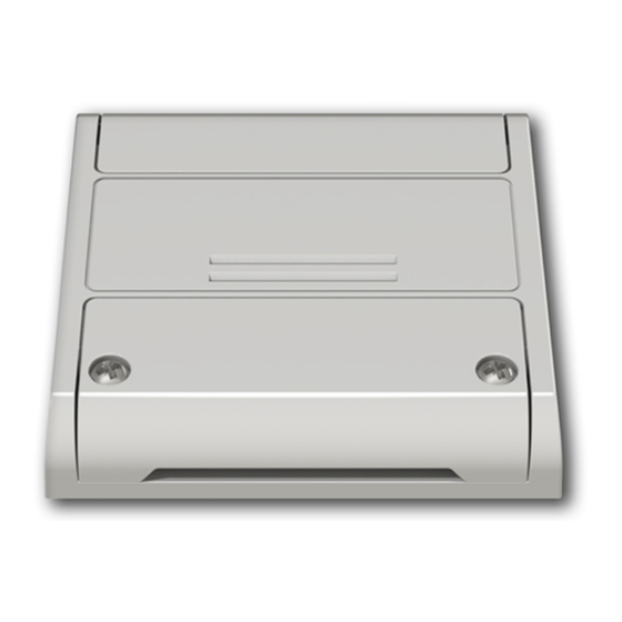
PLANO-ONE/4
OneSmart
note: voice control compatibility
is only available where 4
synchronised outputs are set
Universal control unit for single colour constant voltage LEDs 12-24Vdc, selectable software for outputs number.
Power supply 12-24Vdc, Max 5A /output (max 10A total).
Integrated 433.92 MHz radio receiver.
WiFi connection for OneSmart App.
Advertisement

Related Manuals for Nexta Tech PLANO-ONE/4


Summary of Contents for Nexta Tech PLANO-ONE/4
- Page 1 PLANO-ONE/4 OneSmart note: voice control compatibility is only available where 4 synchronised outputs are set Universal control unit for single colour constant voltage LEDs 12-24Vdc, selectable software for outputs number. Power supply 12-24Vdc, Max 5A /output (max 10A total). Integrated 433.92 MHz radio receiver.
- Page 2 INDEX 1 - PRODUCT FEATURES 1.1 - TECHNICAL DATA page 3 2 - CONNECTION DIAGRAMS 2.1 - SINGLE-COLOR CONNECTION DIAGRAM page 4 2.2 - CONNECTING TWO LINES OF SINGLE-COLOUR STRIP LIGHTS page 5 2.3 - CONNECTING THREE LINES OF SINGLE-COLOUR STRIP LIGHTS page 6 2.4 - CONNECTING FOUR LINES OF SINGLE-COLOUR STRIP LIGHTS...
- Page 3 1 - PRODUCT FEATURES 1.1 TECHNICAL DATA Power supply (Input) 12 - 24 Vdc Constant tension LED type (Output) single color LED 5A per output, Max power load (Output) max 10 A total (4 outputs) N° of programmable transmitters RF receiver frequency 433.920MHz WiFi frequency 2.4GHz...
-
Page 4: Connection Diagrams
2 - CONNECTION DIAGRAMS This control unit can manage 1, 2, 3 or 4 lines of single-colour LED strip lights. By default, operation is set to two single-colour strip lights. If a different strip type is used, follow the paragraph 3 procedure. RECOMMENDATIONS •... - Page 5 2.2 CONNECTING TWO LINES OF SINGLE-COLOUR STRIP LIGHTS By default, operation is set to two single-colour strip lights. (1) (2) (3) (4) (5) (6) (7) (8) (9) (10) Power supply LED line LED line Button 12/24Vdc WARNING: • Connect up to 5A per output and max total 10A •...
- Page 6 2.3 CONNECTING THREE LINES OF SINGLE-COLOUR STRIP LIGHTS The control unit is set by default to manage two lines of single-colour strip lights. To change the setting, follow the procedure in paragraph 3. (1) (2) (3) (4) (5) (6) (9) (10) Power supply 3 lines of single-colour Push button...
-
Page 7: Short Press
2.4 CONNECTING FOUR LINES OF SINGLE-COLOUR STRIP LIGHTS The control unit is set by default to manage two lines of single-colour strip lights. To change the setting, follow the procedure in paragraph 3. (1) (2) (3) (4) (5) (6) (9) (10) Power supply 4 lines of single-colour Push button... - Page 8 3 - LOAD TYPE SETTING Default: One line of single-colour LEDs. This procedure allows you to change the type of the connected LED. WARNING: - The procedure of connection with the OneSmart APP (see paragraph 6) must be repeated each time the load type is changed.
- Page 9 3.2 - PROCEDURE FOR SETTING THE LED TYPE PROCEDURE STEP 1 Press and hold buttons 1 and 2 simultaneously (approximately 2 seconds) until the LED becomes green. ACTION: Long press of buttons 1 and 2 LED: green STEP 2 Make a short press of button 1 on the receiver and count the number of LED Flashes.
- Page 10 4 - USE OF THE CONTROL UNIT 4.1 TYPICAL INSTALLATION The system can be controlled by a wired push button, radio commands, smartphone App OneSmart or voice commands. The installation can operate with only radio controls or application only. Instead, to use voice commands, at least the App configuration must be completed. NEXTA CONTROL UNIT RADIOTRANSMITTER CONFIGURATION...
- Page 11 4.2 USE VIA WIRE The wired button always controls all connected LED lines for the On/Off function (press and release) and the Up/Down dimmer (press and hold). 4.3 USE VIA RADIO To control the loads via radio you must have compatible transmitters and therefore must carry out the association procedure, see paragraph 5.
-
Page 12: Radio Programming
5 - MANAGEMENT WITH REMOTE CONTROL This procedure lets you programme/delete compatible multifunctional or generic (Wireless bus) transmitters. Multifunctional transmitters: With multifunctional transmitters the transmitter control modes depend on the model used. Refer to the transmitter manual, to the paragraph entitled “commands sent by the transmitter”, bearing in mind that: this is a dimmer device. - Page 13 5.2 - DELETION OF REMOTE CONTROL These procedures let you delete from the memory transmitters that have already been programmed. STEP 1 Hold the receiver button 1 down (about 5 seconds.) until the LED begins to Flash. ACTION: Hold tbutton 1 down LED: Flashes red DELETION OF SINGLE DELETION OF ALL...
- Page 14 6 - CONTROL WITH APP ONE SMART These procedures allow you to manage the light from your device (example: mobile phone) through the application and to control the system remotely. 6.1 - APP CONNECTION This procedure connects the control unit Plano-One to the application. It shall be repeated for each control unit on the installation.
- Page 15 6.2 - USE OF THE APP ONE SMART After all the control units have been set up, the installation can be managed by the application. The “Home” menu (1) shows all the associated devices. To send a command to a device, select it. Pressing “Smart”...
- Page 16 7 - CONTROL BY VOICE COMMANDS You can use this procedure to associate a “OneSmart” account with a Google or Alexa account to enable the voice commands. NOTE: voice control compatibility is only available where 4 synchronised outputs are set 7.1 - CONNECTION TO “GOOGLE HOME”...
- Page 17 USE OF “GOOGLE HOME” SENDING VOICE COMMANDS Using your Android mobile phone (or tablet), voice commands can already be sent via the native assistant. By using an Apple device, you can use the microphone within the Google Home application.If you want to add a voice recognition device such as “Google Home Mini”...
- Page 18 7.2 - COONECTION TO “AMAZON ALEXA” PROCEDURE WARNING: before proceeding with this procedure, you must have set up the “OneSmart” account, see paragraph 6. 1. Download the App “Amazon Alexa” 2. After starting the application, you will need to create an account Amazon. Complete the procedure.
- Page 19 USE OF “AMAZON ALEXA” SENDING VOICE COMMANDS Using your Android mobile phone (or tablet), voice commands can already be sent via the Amazon Alexa application. Using an Apple device, you can use the microphone inside the Amazon Alexa application. If you want to add a voice-control device like “Echo Dot” or “Echo Plus”, follow the procedures to match it to the house you created, and then they will be associated with the lights.
-
Page 20: Advanced Programs
8 - ADVANCED PROGRAMS 8.1 FUNCTION CUSTOMIZATION OF THE “WIRELESS BUS” GENERIC TRANSMITTER BUTTONS The following procedure allows you to set a custom function to the “wireless bus” family transmitter button. Details on selectable functions. Function 5 - Memo Each time the button is pressed, the load will Flash to indicate that the current state of the light is stored. If the button is pressed from state “light off”, the storage is switched off and the light will be turned back on to the last set value, as it is by default. - Page 21 PROCEDURE STEP 1 Press key 1 as many times as the output number on which you want to program the transmitter no. of presses LED colour Output paired with TX OUT1 green OUT2 OUT3 yellow OUT4 ACTION: Short press of button 1 LED: Turns on red STEP 2 Press the button 2 on the receiver for a short time and count the number of Flashes emitted by the LED:...
- Page 22 8.2 - LOAD STATE WHEN THE CONTROL UNIT IS SWITCHED ON Default: Last value before the black out This process is used to set the state of Leds when the control unit is switched on (for example when the power supply is provided by a general switch or timer).
- Page 23 8.3 - SETTING THE TIMED ON Default: 24 hours This procedure is used to set the time for which the Leds stays on before an automatic switch off. All commands reset the time count to zero, excluding the following commands that will immediately turn off the light: short press by wired push button, command OFF by radiotransmitter, comand by App or voice.
- Page 24 8.4 - SETTING TYPE OF INPUTS VIA WIRE Default: Button function This procedure lets you choose the type of wired devices to command load (connected on terminals 9 and 10). The devices can be set as buttons or switches. PROCEDURE STEP 1 With a paper clip makes a long press of the “hidden”...
- Page 25 8.4 - RESET OF THE CONTROL UNIT This procedure let you take the control unit back to factory settings. ATTENTION: the only parameter that will not be removed will be the association with the ONESMART application (see paragraph 6). To edit or delete also this parameter, reed the procedure. PROCEDURE STEP 1 Hold the receiver button 1 down (about 5 seconds.) until the...
-
Page 26: First Checks
9 - INSIGHTS 9.1 – ISSUES WHEN CONNECTING THE CONTROL UNIT WITH WIFI If you’re having problems connecting the control unit to the router, we suggest to: FIRST CHECKS: - check if the network used to connect the control unit is running at 2.4GHz (not 5GHz) - the smartphone you use must be connected to the same WiFi on which you want to connect the device - please check if the entered password is correct STEPS TO DO:... - Page 28 MNLPLN-ONEENV1.0 Nexta Tech company brand of Team srl via G.Oberdan 90, 33074 Fontanafredda (PN) - Italy Ph. +39 0434 998682 Email: info@nexta-tech.com Web: www.nexta-tech.com...
Need help?
Do you have a question about the PLANO-ONE/4 and is the answer not in the manual?
Questions and answers