Table of Contents
Advertisement
Quick Links
TOP-ML/One
SCREEN-ML/One
Screen-ML400/One
Top-ML400/One
Electronic control unit for the automation of one 230Vac motor with built-in limit switch and 1, 2 or 3 led line in costant
voltage tension (number of led output settable).
Motor and control unit power supply: 230Vac
Led power supply: 12 or 24Vdc
Motor output: 230 Vac max 1000 W
Led output: 5A for output (3out), max 10A in total
433.92 MHz receiver for radio transmitters.
WiFi connection for OneSmart App.
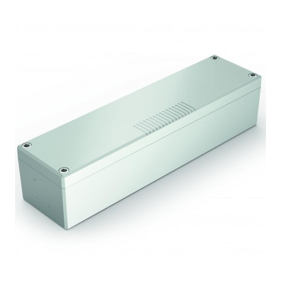
Top-ML/One: control unit in IP20 casing
Screen-ML/One: control unit in outdoor plastic box IP56
Advertisement
Table of Contents

Related Manuals for Nexta Tech TOP-ML/One


Summary of Contents for Nexta Tech TOP-ML/One
- Page 1 Motor output: 230 Vac max 1000 W Led output: 5A for output (3out), max 10A in total 433.92 MHz receiver for radio transmitters. WiFi connection for OneSmart App. Top-ML/One: control unit in IP20 casing Screen-ML/One: control unit in outdoor plastic box IP56...
- Page 2 INDEX 1 - PRODUCT FEATURES 1.1 - TECHNICAL DATA Page 3 1.2 - SENSOR MANAGEMENT Page 3 2 - MOTOR AND SENSORS ELECTRICAL CONNECTIONS Page 4 3 - LED OUTPUT ELECTRICAL CONNECTIONS 3.1 - CONNECTING ONE LINE OF SINGLE-COLOUR STRIP LIGHTS Page 5 3.2 - CONNECTING TWO LINES OF SINGLE-COLOUR STRIP LIGHTS Page 6...
-
Page 3: Sensor Management
1 - PRODUCT FEATURES 1.1 TECHNICAL DATA Control unit power supply (Input) 230 Vac Led power supply 12 or 24Vdc Motor Output 230Vac max 1000W Led output 5A for output, max 10A in total Number of programmable transmitters Receiver frequency RF 433.920MHz Operating temperature -10°... - Page 4 2 - MOTOR AND SENSORS ELECTRICAL CONNECTIONS WARNINGS • Installation must be carried out only by qualified technicians in compliance with the electrical and safety standards in force. • All connections must be made with the power turned off. • Use suitable cables.
- Page 5 3 - LED OUTPUT ELECTRICAL CONNECTIONS This control unit can manage 1, 2 or 3 lines of single-colour LED strip lights. By default, operation is set to one li strip lights. If a different strip type is used, follow the paragraph 2.4 procedure. 3.1 CONNECTING ONE LINE OF SINGLE-COLOUR STRIP LIGHTS With the default settings the control unit is set to control the three LED lines with synchronized operation.
- Page 6 3.2 CONNECTING TWO LINES OF SINGLE-COLOUR STRIP LIGHTS With the default settings the control unit is set to control the three LED lines with synchronized operation. Change the setting, follow the procedure in paragraph 3.4. TERMINAL DESCRIPTION NUMBER (in) 230V phase power supply 230V neutral power supply (out) 230V phase (for accessories power supply)
- Page 7 3.3 CONNECTING THREE LINES OF SINGLE-COLOUR STRIP LIGHTS With the default settings the control unit is set to control the three LED lines with synchronized operation. Change the setting, follow the procedure in paragraph 3.4. TERMINAL DESCRIPTION NUMBER (in) 230V phase power supply 230V neutral power supply (out) 230V phase (for accessories power supply)
- Page 8 3.4 - PROCEDURE FOR SETTING NUMBER OF LED OUTPUT PROCEDURE STEP 1 Press and hold buttons 1 and 3 simultaneously (approximately 2 seconds) until the LED becomes sky blu. ACTION: Long press of buttons 1 and 3 LED: sky blu STEP 2 Make a short press of button 1 on the receiver and count the number of LED Flashes.
- Page 9 4 - SETTING UP CONTROL UNIT To make the control panel work correctly: - Make the connections as shown in the diagram on the previous page, if there are sensors, check that the default operation is correct or, alternatively, modify them, see paragraph 6.2, 6.3 and 6.4. - If you want to control the system via radio control, associate the radio transmitter with the desired output (s), see paragraph 5.
-
Page 10: Radio Programming
5 - MANAGEMENT WITH REMOTE CONTROL This procedure lets you programme/delete compatible multifunctional or generic (Wireless bus) transmitters. Multifunctional transmitters: With multifunctional transmitters the transmitter control modes depend on the model used. Refer to the transmitter manual, to the paragraph entitled “commands sent by the transmitter”, bearing in mind that: this is a dimmer and motor device. - Page 11 5.2 - DELETION OF REMOTE CONTROL These procedures let you delete from the memory transmitters that have already been programmed. STEP 1 Hold the receiver button 1 down (about 5 seconds.) until the LED begins to Flash ACTION: Hold tbutton 1 down LED: Flashes red DELETION OF SINGLE DELETION OF ALL TRANSMITTER...
-
Page 12: Advanced Programs
6 - ADVANCED PROGRAMS 6.1 - CONFIGURATION OF MANEUVER TIMES Default: 60 seconds This procedure is used to set the opening and closing manoeuvre time (maximum time that can be set 180 seconds). NOTE: Before carrying out this procedure check that the direction of operation is correct in relation to the transmitter keys or wired command. -
Page 13: Rain Sensor
.2 CONFIGURATION OF THE FUNCTIONALITIES OF THE SENSORS Default: wind = opens when a wind speed exceeds 10km / h is detected rain = closes when rain is detected sun = closes when sun is detected This procedure is used to set the actions of the motor upon intervention of the sensor alarms STEP 1 Make a long press of button 3. - Page 14 3 CONFIGURATION OF THE FUNCTIONALITIES OF THE SENSORS With this procedure the sensors are tested. ATTENTION: to carry out the test the sensor must be active, see paragraph 5.2 STEP 1 Make a long press of button 3. The led change color cyclically red and green. Release the button corresponding to the sensor you want to set LED colour Output paired with TX...
- Page 15 6.4 SETTING THE DEVICES CONNECTED TO THE WIRED INPUTS Default: Input1= Wind sensor Input2= Rain sensor Input3= Sun sensor This procedure changes the type of device connected to the wired inputs. The device can be a sensor or a button dedicated to controlling the movement of the motors or control the lights.
- Page 16 6.5 - RESET OF THE CONTROL UNIT This procedure let you take the control unit back to factory settings. STEP1 Hold the receiver button 1 down (about 5 seconds.) until the LED begins to Flash ACTION: Long press of button 1 LED: The led Flash quicly STEP2 Within 10 seconds, make a short press of button 2.
- Page 17 7 - INSIGHTS 7.1 - SIGNALING OF ALARMS The control unit, through the LED and the buzzer on the board, is able to signal any alarms of the active weather sensors. When the control unit receives a command for the movement of the motor but this is inhibited due to an alarm, a “BEEP”...
- Page 18 8 - CONTROL WITH APP ONE SMART These procedures allow you to manage the light from your device (example: mobile phone) through the application and to control the system remotely. 8.1 - APP CONNECTION This procedure connects the control unit to the application. It shall be repeated for each control unit on the installation. ATTENTION: an internet-based 2,4GHz Wi-Fi (no 5GHz) network is required for this operation.
-
Page 19: First Checks
9 - INSIGHTS 9.1 – ISSUES WHEN CONNECTING THE CONTROL UNIT WITH WIFI If you’re having problems connecting the control unit to the router, we suggest to: FIRST CHECKS: - check if the network used to connect the control unit is running at 2.4GHz (not 5GHz) - the smartphone you use must be connected to the same WiFi on which you want to connect the device - please check if the entered password is correct STEPS TO DO:... - Page 24 Nexta Tech company brand of Team srl via G.Oberdan 90, 33074 Fontanafredda (PN) - Italy Ph. +39 0434 998682 Email: info@nexta-tech.com Web: www.nexta-tech.com...
Need help?
Do you have a question about the TOP-ML/One and is the answer not in the manual?
Questions and answers