
Related Manuals for Nexta Tech MCX-M500


Summary of Contents for Nexta Tech MCX-M500
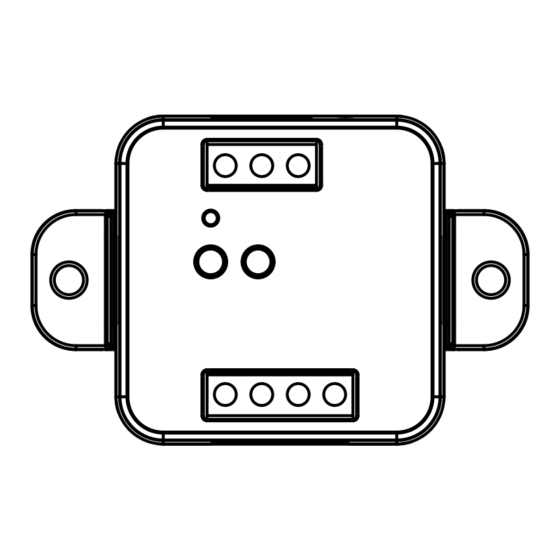
- Page 1 MCX-M500 Control unit for 230Vac motors with built-in dip switches. Power supply 230Vac, Max 500W. Integrated 433,92 MHz radio receiver.
- Page 2 INDEX 1 - PRODUCT FEATURES 1.1 - TECHNICAL DATA page 3 2 - CONNECTION DIAGRAMS 2.1 - CONNECTION DIAGRAM WITH NEUTRAL FROM CONTROL UNIT page 4 2.2 - CONNECTION DIAGRAM WITH NEUTRAL FROM THE ELCTRICAL SYSTEM page 5 3 - USE OF THE CONTROL UNIT 3.1 - TYPICAL INSTALLATION page 6 3.2 - USE VIA WIRE...
- Page 3 1 - PRODUCT FEATURES 1.1 TECHNICAL DATA Power supply (Input) 230Vac Load type (Output) 230Vac motor with built-in limit switches Max power load (Output) 500W N° of programmable transmitters RF receiver frequency 433,920MHz Protection rating IP20 Working temperature -20° +55° Box dimensions 52x43x21 mm P1 Key...
-
Page 4: Connection Diagrams
2 - CONNECTION DIAGRAMS RECOMMENDATIONS • Installation must be carried out only by professional technicians in accordance with the applicable electrical and safety regulations. • All connections shall be operated without electrical voltage. • Use proper cables. • Don’t cut the antenna •... - Page 5 2.2 CONNECTION DIAGRAM WITH NEUTRAL FROM THE ELECTRICAL SYSTEM OUT 230V max 500W OP C CL P1 P2 P1 P2 Filar inputs can be set to: - Mono/Double Button, see paragraph 7.3 - Automatic/man-present operation, see paragraph 7.4...
- Page 6 3 - USE OF THE CONTROL UNIT 3.1 TYPICAL INSTALLATION The system can be controlled by a wired push button, radio commands. The installation can operate with only radio controls. NEXTA CONTROL UNIT RADIOTRANSMITTER CONFIGURATION See paragraph 4...
- Page 7 3.2 USE VIA WIRE Once connected, the button is already active with Open/Stop/Close function. 3.3 USE VIA RADIO To control the load via radio you must have compatible transmitters and therefore must carry out the association procedure, see paragraph 4.
- Page 8 4 - MANAGEMENT WITH REMOTE CONTROL This procedure lets you programme/delete compatible transmitters. 4.1 - RADIO PROGRAMMING This procedure lets you programme compatible multifunctional or generic transmitters. STEP 1 Press the button P1 on the receiver for a short time. The LED comes red on and stays on.
- Page 9 4.2 - DELETION OF REMOTE CONTROL These procedures let you delete from the memory transmitters that have already been programmed. STEP 1 Hold the receiver button P1 down (about 8 seconds.) until the LED begins to Flash. ACTION: Hold button P1 down LED: Flashes red DELETION OF SINGLE DELETION OF ALL...
-
Page 10: Advanced Programs
5 - ADVANCED PROGRAMS 5.1 - CONFIGURATION OF MANEUVER TIMES Default: 60 seconds This procedure is used to set the opening and closing manoeuvre time (maximum time that can be set 180 seconds). STEP 1 Make short pressures of the P2 button. Each time the LED changes colour green/yellow/magenta/ green... - Page 11 5.2 - FUNCTION CUSTOMIZATION OF THE “WIRELESS BUS” GENERIC TRANSMITTER BUTTONS The following procedure allows you to set a custom function to the “wireless bus” family transmitter button. PROCEDURE STEP 1 Press the button P1. The led turns on red. ACTION: Short press of button P1 LED: Turns on red STEP 2...
- Page 12 5.3 - WIRED INPUT SETTING Default: Mono button This procedure lets you select the function of inputs “P1” (terminal 3) and “P2” (terminal 4). WARNING: the connected devices must be buttons. PROCEDURE STEP 1 Make short pressures of the P2 button. Each time the LED changes color: green/yellow/magenta/ green...
- Page 13 5.4 - WIRED INPUT MODE SETTING Default: automatic This procedure allows you to select the mode of operation between: automatic: after pressing the button the automation completes the movement to the limit switch present man: automation moves until the button is pressed PROCEDURE STEP 1 Make short pressures of the P2 button.
- Page 14 5.5 - RESET OF THE CONTROL UNIT This procedure let you take the control unit back to factory settings. PROCEDURE STEP 1 Hold the receiver button P1 down (about 4 seconds.) until the LED begins to Flash red. ACTION: Hold button P1 down LED: Flashes red STEP 2 Within 10 seconds, make a short press of P2 button.
- Page 18 Nexta Tech company brand of Team srl via G.Oberdan 90, 33074 Fontanafredda (PN) - Italy Ph. +39 0434 998682 Email: info@nexta-tech.com Web: www.nexta-tech.com...
Need help?
Do you have a question about the MCX-M500 and is the answer not in the manual?
Questions and answers