
Related Manuals for Balluff BTL7-S5 (B) M P S32/S115/S147/KA FA Series


Summary of Contents for Balluff BTL7-S5 (B) M P S32/S115/S147/KA FA Series
- Page 1 BTL7-S5_ _(B) -M _ _ _ _ -P-S32/S115/S147/KA_ _/FA_ _ deutsch Betriebsanleitung User’s guide english Notice d’utilisation français italiano Manuale d’uso español Manual de instrucciones 中文 用户指南 한국어 사용자 가이드...
- Page 2 www.balluff.com...
- Page 3 BTL7-S5_ _(B) -M _ _ _ _ -P-S32/S115/S147/KA_ _/FA_ _ Betriebsanleitung deutsch...
- Page 4 www.balluff.com...
- Page 5 Hinweise zum Betrieb SSI-Schnittstelle Prinzip Datenformate Fehlerhafte SSI-Abfrage Synchroner und asynchroner Betrieb Konfiguration mit dem BTL7 Configuration Tool Micropulse Configuration Tool Anschluss der USB-Kommunikationsbox Konfigurationsmöglichkeiten Technische Daten Genauigkeit Umgebungsbedingungen Spannungsversorgung Ausgang Kommunikationsleitungen La, Lb Maße, Gewichte Verbindung zur Auswerteeinheit www.balluff.com deutsch...
- Page 6 BTL7-S5_ _(B) -M _ _ _ _ -P-S32/S115/S147/KA_ _/FA_ _ Magnetostriktives Positionsmesssystem – Bauform Profil Zubehör Geführte Positionsgeber Gelenkstange BTL2-GS10-_ _ _ _-A Freie Positionsgeber Steckverbinder S32 9.4.1 Frei konfektionierbar 9.4.2 Konfektioniert Steckverbinder S115, konfektioniert USB-Kommunikationsbox Typenschlüssel Anhang 11.1 Umrechnung Längeneinheiten 11.2 Typenschild deutsch...
- Page 7 Konformitätserklärung aufgeführt. Die Positionsgeber sind in unterschiedlichen Bauformen lieferbar und deshalb gesondert zu bestellen. Verwendete Abkürzungen Synchron-Serielle Schnittstelle (Synchronous Zulassungen und Kennzeichnungen Serial Interface) Nicht bei BTL7-…-FA_ _ US-Patent 5 923 164 Das US-Patent wurde in Verbindung mit diesem Produkt erteilt. www.balluff.com deutsch...
- Page 8 Die verwendeten Warnhinweise enthalten verschiedene gemäß den Angaben in den technischen Daten wird nur Signalwörter und sind nach folgendem Schema aufgebaut: mit original Balluff Zubehör zugesichert, die Verwendung anderer Komponenten bewirkt Haftungsausschluss. SIGNALWORT Das Öffnen des BTL oder eine nichtbestimmungsgemäße Art und Quelle der Gefahr Verwendung sind nicht zulässig und führen zum Verlust...
- Page 9 Positionsgeber: Definiert die zu messende Position auf dem Wellenleiter. Positionsgeber sind in unterschiedlichen Bauformen lieferbar und gesondert zu bestellen (siehe Zubehör ab Seite 21). Nennlänge: Um das BTL optimal an die Anwendung anzupassen, sind Nennlängen von 50 mm bis 7620 mm lieferbar. www.balluff.com deutsch...
- Page 10 BTL7-S5_ _(B) -M _ _ _ _ -P-S32/S115/S147/KA_ _/FA_ _ Magnetostriktives Positionsmesssystem – Bauform Profil Aufbau und Funktion (Fortsetzung) Funktion LED 1 Normalfunktion Grün Im BTL befindet sich der Wellenleiter, geschützt durch ein Positionsgeber ist innerhalb der Grenzen. Aluminiumgehäuse. Entlang des Wellenleiters wird ein Positionsgeber bewegt.
- Page 11 Maße und Abstände mit Positionsgeber BTL5-T-2814-1S für geführte Positionsgeber (siehe Bild 4-1 bis Bild 4-3). Bild 4-3: Maße und Abstände mit Positionsgeber BTL5-M/N-2814-1S BTL5-M-2814-1S BTL5-N-2814-1S Abstand X 48,5 mm 57 mm Abstand Y 51 mm 59,5 mm Tab. 4-1: Abstände für Positionsgeber BTL5-M/N-2814-1S www.balluff.com deutsch...
- Page 12 BTL7-S5_ _(B) -M _ _ _ _ -P-S32/S115/S147/KA_ _/FA_ _ Magnetostriktives Positionsmesssystem – Bauform Profil Einbau und Anschluss (Fortsetzung) Freie Positionsgeber Beim Einbau des Positionsgebers ist zu beachten: – Um die Genauigkeit des Wegmesssystems zu gewähr- leisten, wird der Positionsgeber mit nichtmagnetisier- baren Schrauben (Edelstahl, Messing, Aluminium) am bewegten Maschinenteil befestigt.
- Page 13 Pinbelegung S32 (Draufsicht auf Stecker am BTL), 8-poliger Rundstecker M16 10…30 V nicht belegt Nicht belegte Adern können steuerungsseitig mit GND verbunden werden, aber nicht mit dem Schirm. Tab. 4-5: Anschlussbelegung BTL7…-S147 Bild 4-11: Pinbelegung S147 (Draufsicht auf Stecker am BTL), 7-poliger Rundstecker M16 www.balluff.com deutsch...
- Page 14 BTL7-S5_ _(B) -M _ _ _ _ -P-S32/S115/S147/KA_ _/FA_ _ Magnetostriktives Positionsmesssystem – Bauform Profil Einbau und Anschluss (Fortsetzung) 4.4.4 Kabelanschluss Schirmung und Kabelverlegung BTL7 Standard BTL7 USB- Definierte Erdung! Configurable BTL und Schaltschrank müssen auf dem gleichen Erdungspotenzial liegen. Adern- BTL7-S5_ _-…-KA/FA BTL7-S510-…-KA/FA farbe BTL7-S5_ _B-…-KA/FA...
- Page 15 Reparatur durch den Hersteller die korrekten Werte im Nullpunkt und Endpunkt prüfen. Hinweise zum Betrieb – Funktion des BTL und aller damit verbundenen Kom- ponenten regelmäßig überprüfen. – Bei Funktionsstörungen das BTL außer Betrieb neh- men. – Anlage gegen unbefugte Benutzung sichern. www.balluff.com deutsch...
- Page 16 BTL7-S5_ _(B) -M _ _ _ _ -P-S32/S115/S147/KA_ _/FA_ _ Magnetostriktives Positionsmesssystem – Bauform Profil SSI-Schnittstelle Prinzip Beim BTL7-S_ _B-M… werden die Positionsdaten syn- chron zur externen Abtastperiode zeitnah ermittelt und SSI bedeutet Synchronous Serial Interface und beschreibt ausgegeben. Für einen synchronen Betrieb muss die eine digitale synchrone Schnittstelle mit einer differenziellen Abtastperiode T im Bereich T...
- Page 17 Bei zu vielen Taktflanken geht der Datenausgang nach -Event Ablauf der korrekten Anzahl von Takten auf Low. Mit jeder weiteren negativen Flanke von Clk wird der t -Timer erneut gestartet und intern der T -Event gesetzt. Nach Ablauf der Zeit t geht Data wieder auf High. www.balluff.com deutsch...
- Page 18 BTL7-S5_ _(B) -M _ _ _ _ -P-S32/S115/S147/KA_ _/FA_ _ Magnetostriktives Positionsmesssystem – Bauform Profil SSI-Schnittstelle (Fortsetzung) Synchroner und asynchroner Betrieb Im synchronen Betrieb müssen zwei Randbedingungen beachtet werden: Synchroner Betrieb – Die externe Abtastfrequenz f muss sich im Bereich Für regeltechnische Anwendungen ist häufig ein gleichmä- 62,5 Hz < f < f befinden.
- Page 19 Endpunkt zum Anfangspunkt mit negativem Die PC-Software und das zugehörige Hand- Vorzeichen. buch erhalten Sie im Internet unter – Geschwindigkeit (kein Vorzeichen): Geschwindig- www.balluff.com. keit des Positionsgebers, die Bewegungsrichtung kann nicht abgelesen werden. – Positionsdifferenz: Abstand zwischen zwei Positions- Anschluss der USB-Kommunikationsbox gebern.
- Page 20 Für UL: Gebrauch in geschlossenen Räumen und bis zu einer Höhe von nach EN 60068-2-27 4), 5) 2000 m über Meeresspiegel. Vibration 20 g, 10…2000 Hz Einzelbestimmung nach Balluff Werknorm nach EN 60068-2-6 4), 5) Resonanzfrequenzen ausgenommen Schutzart nach IEC 60529 Für UL: Das BTL muss extern über einen energiebegrenzten Stromkreis...
- Page 21 Kabelmaterial cULus 20549 80 °C, 300 V, internal wiring Kabeltemperatur –40…+90 °C Kabeldurchmesser max. 7 mm zulässiger Biegeradius feste Verlegung ≥ 35 mm bewegt ≥ 105 mm BTL7-...-FA_ _ Kabelmaterial PTFE keine UL-Zulassung verfügbar Kabeltemperatur –55…+200 °C Kabeldurchmesser max. 7 mm zulässiger Biegeradius feste Verlegung ≥ 35 mm bewegt kein zulässiger Biegeradius www.balluff.com deutsch...
- Page 22 BTL7-S5_ _(B) -M _ _ _ _ -P-S32/S115/S147/KA_ _/FA_ _ Magnetostriktives Positionsmesssystem – Bauform Profil Technische Daten (Fortsetzung) Verbindung zur Auswerteeinheit Die maximale Abtastfrequenz f , bei der mit jeder Abtas- Die minimale Abtastfrequenz f beträgt 62,5 Hz. A,max A,min tung ein neuer aktueller Wert ansteht, lässt sich aus der folgenden Grafik entnehmen: in Hz A,max...
- Page 23 Aluminium Gleitfläche: Kunststoff Kunststoff Beispiel: BTL2-GS10-0100-A (Nennlänge = 100 mm) BTL5-F-2814-1S M5x10 Bild 9-2: Einbaumaße Positionsgeber BTL5-F-2814-1S Gewicht: ca. 28 g Gehäuse: Aluminium Gleitfläche: Kunststoff BTL5-T-2814-1S Bild 9-3: Einbaumaße Positionsgeber BTL5-T-2814-1S Gewicht: ca. 28 g Gehäuse: Aluminium Gleitfläche: Kunststoff www.balluff.com deutsch...
- Page 24 BTL7-S5_ _(B) -M _ _ _ _ -P-S32/S115/S147/KA_ _/FA_ _ Magnetostriktives Positionsmesssystem – Bauform Profil Zubehör (Fortsetzung) Freie Positionsgeber BTL6-A-3801-2 37.6 BTL5-P-3800-2 Ø 4.2 Ø 4.2 Bild 9-8: Einbaumaße Positionsgeber BTL6-A-3801-2 Gewicht: ca. 25 g Bild 9-5: Einbaumaße Positionsgeber BTL5-P-3800-2 Gehäuse: Kunststoff Gewicht: ca.
- Page 25 Steckverbinder gewinkelt, M16 nach IEC 130-9, 8-polig ~ 54 48.5 Bild 9-13: Steckverbinder S32 (konfektioniert) Ø 20 Farbe YE Gelb Bild 9-11: Steckverbinder BKS-S 33M-00 GY Grau PK Rosa RD Rot GN Grün BU Blau BN Braun WH Weiß Tab. 9-1: Pinbelegung S32 (konfektioniert) www.balluff.com deutsch...
- Page 26 BTL7-S5_ _(B) -M _ _ _ _ -P-S32/S115/S147/KA_ _/FA_ _ Magnetostriktives Positionsmesssystem – Bauform Profil Zubehör (Fortsetzung) Steckverbinder S115, konfektioniert USB-Kommunikationsbox BKS-S115-PU-_ _ BTL7-A-CB01-USB-S32 Steckverbinder gerade, angespritzt, M12, 8-polig Für BTL7-S510(B)-… mit S32-Steckverbinder. Unterschiedliche Kabellängen bestellbar, z. B. Lieferumfang: USB-Kommunikationsbox, USB-Kabel, BKS-S115-PU-05 (Bestellcode BCC00YF): Kabellänge 5 m 2 Adapterkabel je ca.
- Page 27 M0500 = metrische Angabe in mm, Nennlänge 500 mm (M0050…M7620) Bauform: P = Profilgehäuse Elektrischer Anschluss: S32 = 8-polig, M16-Stecker nach IEC 130-9 S115 = 8-polig, M12-Stecker S147 = 7-polig, M16-Stecker nach DIN 45329 KA05 = Kabel 5 m (PUR) FA05 = Kabel 5 m (PTFE) www.balluff.com deutsch...
- Page 28 BTL7-S5_ _(B) -M _ _ _ _ -P-S32/S115/S147/KA_ _/FA_ _ Magnetostriktives Positionsmesssystem – Bauform Profil Typenschlüssel (Fortsetzung) BTL7 USB-Configurable BTL7 - S 5 1 0 B - M0500 - P - S32 SSI-Schnittstelle Versorgungsspannung: 5 = 10…30 V DC Datenformat: 1 = 24 Bit, Gray, steigend (Werkseinstellung) Auflösung: 0 = 1 µm (Werkseinstellung) Synchroner/asynchroner Betrieb:...
- Page 29 0,03937008 25,4 0,07874016 50,8 0,11811024 76,2 0,15748031 101,6 0,19685039 0,23622047 152,4 0,27559055 177,8 0,31496063 203,2 0,35433071 228,6 0,393700787 Tab. 11-1: Umrechnungstabelle mm-inch Tab. 11-2: Umrechnungstabelle inch-mm 11.2 Typenschild Bestellcode Seriennummer Nullmarkierung Bild 11-1: Typenschild BTL7 (Beispiel) www.balluff.com deutsch...
- Page 31 BTL7-S5_ _(B) -M _ _ _ _ -P-S32/S115/S147/KA_ _/FA_ _ User’s Guide english...
- Page 32 www.balluff.com...
- Page 33 Synchronous and asynchronous operation Configuration using the BTL7 Configuration Tool BTL7 Configuration Tool Connecting the USB communication box Configuration options Technical data Accuracy Ambient conditions Supply voltage Output Communication lines La, Lb Dimensions, weights Connection to the evaluation unit www.balluff.com english...
- Page 34 BTL7-S5_ _(B) -M _ _ _ _ -P-S32/S115/S147/KA_ _/FA_ _ Magnetostrictive Linear Position Sensor – Profile Style Accessories Captive magnets BTL2-GS10-_ _ _ _-A joint rod Floating magnets Connector type S32 9.4.1 Freely configurable 9.4.2 Preassembled Connector type S115, preassembled USB communication box Type code Appendix 11.1 Converting units of length...
- Page 35 The magnets are available in various models declaration of conformity. and must be ordered separately. Approvals and markings Abbreviations Synchronous Serial Interface Not for BTL7-…-FA_ _ US Patent 5 923 164 The US patent was awarded in connection with this product. www.balluff.com english...
-
Page 36: Signal Word
The warnings used here contain various signal words and Flawless function in accordance with the specifications in are structured as follows: the technical data is ensured only when using original Balluff accessories. Use of any other components will void SIGNAL WORD the warranty. Hazard type and source... - Page 37 Magnet: Defines the position to be measured on the waveguide. Magnets are available in various models and must be ordered separately (see Accessories starting on page 21). Nominal length: To optimally adapt the BTL to the application, nominal lengths from 50 mm to 7620 mm are available. www.balluff.com english...
- Page 38 BTL7-S5_ _(B) -M _ _ _ _ -P-S32/S115/S147/KA_ _/FA_ _ Magnetostrictive Linear Position Sensor – Profile Style Construction and function (continued) Function LED 1 Normal function Green The BTL contains the waveguide which is protected by an Magnet is within the limits. aluminum housing. A magnet is moved along the waveguide.
- Page 39 (see Fig. 4-1 to Fig. 4-3). Fig. 4-2: Dimensions and distances with BTL5-T-2814-1S magnet Fig. 4-3: Dimensions and distances with BTL5-M/N-2814-1S magnet BTL5-M-2814-1S BTL5-N-2814-1S Distance X 48.5 mm 57 mm Distance Y 51 mm 59.5 mm Tab. 4-1: Distances with BTL5-M/N-2814-1S magnet www.balluff.com english...
- Page 40 BTL7-S5_ _(B) -M _ _ _ _ -P-S32/S115/S147/KA_ _/FA_ _ Magnetostrictive Linear Position Sensor – Profile Style Installation and connection (continued) Floating magnets The following must be observed when installing the magnet: – To ensure the accuracy of the position measuring system, the magnet is attached to the moving member of the machine using non-magnetizable screws (stainless steel, brass, aluminum).
- Page 41 Not used Unassigned leads can be connected to the GND on the controller side but not to the shield. Tab. 4-5: Connection assignment BTL7…-S147 Fig. 4-11: Pin assignment of S147 (view from above on BTL), 7-pin M16 circular plug www.balluff.com english...
-
Page 42: Magnetic Fields
BTL7-S5_ _(B) -M _ _ _ _ -P-S32/S115/S147/KA_ _/FA_ _ Magnetostrictive Linear Position Sensor – Profile Style Installation and connection (continued) 4.4.4 Cable connection Shielding and cable routing BTL7 standard BTL7 USB- Defined ground! Configurable The BTL and the control cabinet must be at the same ground potential. - Page 43 BTL or after repair by the manufacturer. Operating notes – Regularly check function of the BTL and all associated components. – Take the BTL out of operation whenever there is a malfunction. – Secure the system against unauthorized use. www.balluff.com english...
- Page 44 BTL7-S5_ _(B) -M _ _ _ _ -P-S32/S115/S147/KA_ _/FA_ _ Magnetostrictive Linear Position Sensor – Profile Style SSI interface Principle With the BTL7-S_ _B-M…, position data is determined and output in a timely manner and synchronous to the SSI stands for Synchronous Serial Interface and describes external sampling period.
- Page 45 The t timer is started again for every additional negative edge from Clk and the T event is set internally. Data switches back to high after the time t elapsed. www.balluff.com english...
- Page 46 BTL7-S5_ _(B) -M _ _ _ _ -P-S32/S115/S147/KA_ _/FA_ _ Magnetostrictive Linear Position Sensor – Profile Style SSI interface (continued) Synchronous and asynchronous operation Two boundary conditions must be taken into account during synchronous operation: Synchronous operation – The external sampling frequency f must be in the A uniform and brief timing is often required for control range 62.5 Hz < f...
- Page 47 The PC software and associated manual can movement from the end point to the starting point is be found in the Internet under www.balluff.com. output with a negative sign. –...
-
Page 48: Ambient Conditions
For UL: Use in enclosed spaces and up to a height of 2000 m above sea Shock rating 150 g/6 ms level. Continuous shock 150 g/2 ms Individual specifications as per Balluff factory standard per EN 60068-2-27 4), 5) Resonant frequencies excluded Vibration 20 g, 10…2000 Hz For UL: The BTL must be externally connected via a limited-energy circuit per EN 60068-2-6... - Page 49 Cable diameter Max. 7 mm Permissible bending radius Fixed routing ≥ 35 mm Moved ≥ 105 mm BTL7-...-FA_ _ Cable material PTFE No UL approval available Cable temperature –55…+200°C Cable diameter Max. 7 mm Permissible bending radius Fixed routing ≥ 35 mm Moved No permissible bending radius www.balluff.com english...
- Page 50 BTL7-S5_ _(B) -M _ _ _ _ -P-S32/S115/S147/KA_ _/FA_ _ Magnetostrictive Linear Position Sensor – Profile Style Technical data (continued) Connection to the evaluation unit The maximum sampling frequency f , at which a new The minimum sampling frequency f is 62,5 Hz. A,max A,min current value is available with each sampling, can be found...
- Page 51 Example: BTL2-GS10-0100-A (nominal length = 100 mm) BTL5-F-2814-1S M5x10 Fig. 9-2: Installation dimensions of BTL5-F-2814-1S magnet Weight: Approx. 28 g Housing: Aluminum Slide surface: Plastic BTL5-T-2814-1S Fig. 9-3: Installation dimensions of BTL5-T-2814-1S magnet Weight: Approx. 28 g Housing: Aluminum Slide surface: Plastic www.balluff.com english...
- Page 52 BTL7-S5_ _(B) -M _ _ _ _ -P-S32/S115/S147/KA_ _/FA_ _ Magnetostrictive Linear Position Sensor – Profile Style Accessories (continued) Floating magnets BTL6-A-3801-2 37.6 BTL5-P-3800-2 Ø 4.2 Ø 4.2 Fig. 9-8: Installation dimensions of BTL6-A-3801-2 magnet Weight: Approx. 25 g Fig. 9-5: Installation dimensions of BTL5-P-3800-2 magnet Housing: Plastic Weight:...
- Page 53 ~ 54 48.5 Fig. 9-13: Connector type S32 (preassembled) Color Ø 20 YE yellow Fig. 9-11: Connector BKS S 33M-00 GY gray PK pink RD red GN green BU blue BN brown WH white Tab. 9-1: S32 (preassembled) pin assignment www.balluff.com english...
- Page 54 BTL7-S5_ _(B) -M _ _ _ _ -P-S32/S115/S147/KA_ _/FA_ _ Magnetostrictive Linear Position Sensor – Profile Style Accessories (continued) Connector type S115, preassembled USB communication box BKS-S115-PU-_ _ BTL7-A-CB01-USB-S32 Straight connector, molded-on cable, M12, 8-pin For BTL7-S510(B)-… with connector type S32. Various cable lengths can be ordered, e.g. Scope of delivery: USB communication box, USB cable, BKS-S115-PU-05 (Order code: BCC00YF): Cable length 2 adapter cables each approx.
- Page 55 M0500 = Metric specification in mm, nominal length 500 mm (M0050…M7620) Construction: P = Profile housing Electrical connection: S32 = 8-pin, M16 plug per IEC 130-9 S115 = 8-pin, M12 plug S147 = 7-pin, M16 plug per DIN 45329 KA05 = Cable, 5 m (PUR) FA05 = Cable, 5 m (PTFE) www.balluff.com english...
- Page 56 BTL7-S5_ _(B) -M _ _ _ _ -P-S32/S115/S147/KA_ _/FA_ _ Magnetostrictive Linear Position Sensor – Profile Style Type code breakdown (continued) BTL7 USB-Configurable BTL7 - S 5 1 0 B - M0500 - P - S32 SSI interface Supply voltage: 5 = 10…30 V DC Data format: 1 = 24 bit, Gray, rising (factory setting) Resolution:...
- Page 57 152.4 0.27559055 177.8 0.31496063 203.2 0.35433071 228.6 0.393700787 Tab. 11-1: Conversion table mm to inches Tab. 11-2: Conversion table inches to mm 11.2 Part label Order code Type Serial number Null mark Fig. 11-1: BTL7 part label (example) www.balluff.com english...
- Page 59 BTL7-S5_ _(B) -M _ _ _ _ -P-S32/S115/S147/KA_ _/FA_ _ Notice d’utilisation français...
- Page 60 www.balluff.com...
- Page 61 Fonctionnements synchrone et asynchrone Configuration avec BTL7 Configuration Tool BTL7 Configuration Tool Raccordement du module de communication USB Possibilités de configuration Caractéristiques techniques Précision Conditions ambiantes Alimentation électrique Sorties Câbles de communication La et Lb Dimensions, poids Connexion à l’unité d’analyse www.balluff.com français...
- Page 62 BTL7-S5_ _(B) -M _ _ _ _ -P-S32/S115/S147/KA_ _/FA_ _ Système de mesure de position magnétostrictif – Forme de construction du profilé Accessoires Capteurs de position guidés Tige articulée BTL2-GS10-_ _ _ _-A Capteurs de position libres Connecteur S32 9.4.1 À assembler 9.4.2 Confectionné Connecteur S115, confectionné...
- Page 63 être commandés séparément. Abréviations utilisées Interface série synchrone Homologations et certifications (Synchronous Serial Interface) Sauf pour BTL7-…-FA_ _ Brevet US 5 923 164 Le brevet américain a été attribué en relation avec ce produit. www.balluff.com français...
- Page 64 MOT-CLE les accessoires d’origine de Balluff, l’utilisation d’autres composants entraîne la nullité de la garantie. Type et source de danger Conséquences en cas de non-respect du danger Tout démontage du BTL ainsi que toute utilisation non...
- Page 65 être commandés séparément (voir Accessoires, à partir de la page 21). Longueur nominale : afin de permettre une adaptation optimale du BTL à l’application, des longueurs nominales de 50 mm à 7620 mm sont disponibles. www.balluff.com français...
- Page 66 BTL7-S5_ _(B) -M _ _ _ _ -P-S32/S115/S147/KA_ _/FA_ _ Système de mesure de position magnétostrictif – Forme de construction du profilé Structure et fonction (suite) Fonction LED 1 Fonctionnement normal Vert Le BTL abrite le guide d’ondes protégé par un boîtier en Le capteur de position est dans les limites. aluminium.
- Page 67 Fig. 4-2 : Dimensions et distances pour le capteur de position (voir Fig. 4-1 à Fig. 4-3). BTL5-T-2814-1S Fig. 4-3 : Dimensions et distances pour le capteur de position BTL5-M/N-2814-1S BTL5-M-2814-1S BTL5-N-2814-1S Distance X 48,5 mm 57 mm Distance Y 51 mm 59,5 mm Tab. 4-1: Distances pour le capteur de position BTL5-M/N-2814-1S www.balluff.com français...
- Page 68 BTL7-S5_ _(B) -M _ _ _ _ -P-S32/S115/S147/KA_ _/FA_ _ Système de mesure de position magnétostrictif – Forme de construction du profilé Montage et raccordement (suite) Capteurs de position libres A prendre en considération lors du montage du capteur de position : – Pour garantir la précision du système de mesure de déplacement, le capteur de position doit être fixé...
-
Page 69: Raccordement Électrique
Les conducteurs non utilisés peuvent être reliés côté commande à la masse GND, mais pas au blindage. Tab. 4-5: Affectation des broches BTL7…-S147 Fig. 4-11 : Affectation des broches du connecteur S147 (vue de dessus sur le connecteur du BTL), connecteur rond à 7 pôles M16 www.balluff.com français... - Page 70 BTL7-S5_ _(B) -M _ _ _ _ -P-S32/S115/S147/KA_ _/FA_ _ Système de mesure de position magnétostrictif – Forme de construction du profilé Montage et raccordement (suite) 4.4.4 Raccordement des câbles Blindage et pose des câbles BTL7 Standard BTL7 USB- Mise à la terre définie ! Configurable Le BTL et l’armoire électrique doivent être reliés au même potentiel de mise à...
- Page 71 BTL ou réparation par le fabricant. Conseils d’utilisation – Contrôler régulièrement le fonctionnement du BTL et de tous les composants associés. – En cas de dysfonctionnement, mettre le BTL hors service. – Protéger l’installation de toute utilisation non autorisée. www.balluff.com français...
- Page 72 BTL7-S5_ _(B) -M _ _ _ _ -P-S32/S115/S147/KA_ _/FA_ _ Système de mesure de position magnétostrictif – Forme de construction du profilé Interface SSI Principe Pour le BTL7-S_ _B-M…, les données de position sont déterminées et émises en temps réel et de manière SSI signifie Synchronous Serial Interface et décrit une synchronisée avec la période d’échantillonnage externe.
- Page 73 à Low après écoulement du nombre correct de cadences. Le minuteur t redémarre à chaque cadence négative supplémentaire de Clk tandis qu’en interne, l’évènement T a lieu. Une fois la durée t écoulée, Data s’élève à nouveau à High. www.balluff.com français...
- Page 74 BTL7-S5_ _(B) -M _ _ _ _ -P-S32/S115/S147/KA_ _/FA_ _ Système de mesure de position magnétostrictif – Forme de construction du profilé Interface SSI (suite) Fonctionnements synchrone et asynchrone Lors du fonctionnement synchrone, deux conditions secondaires doivent être remplies : Fonctionnement synchrone – La fréquence d’échantillonnage externe f doit être Pour les applications de régulation, un minutage court et comprise entre 62,5 Hz < f...
- Page 75 – Différence de position : distance entre deux capteurs Internet www.balluff.com. de position. La sélection est uniquement possible lorsque deux capteurs de position sont sélectionnés. –...
- Page 76 Pour UL : utilisation à l’intérieur et jusqu’à une altitude max. de 2000 m selon EN 60068-2-6 4), 5) au-dessus du niveau de la mer. Protection selon CEI 60529 Détermination individuelle selon la norme d’usine Balluff Connecteur S32/S115/ IP67 Exception faite des fréquences de résonance S147 (à l’état vissé) Pour UL : le BTL doit être raccordé...
- Page 77 ≥ 35 mm Pose mobile ≥ 105 mm BTL7-...-FA_ _ Matériau du câble PTFE Aucune homologation UL disponible Température de câble –55 … +200 °C Diamètre de câble Max. 7 mm Rayon de courbure autorisé Pose fixe ≥ 35 mm Pose mobile Aucun rayon de courbure autorisé www.balluff.com français...
- Page 78 BTL7-S5_ _(B) -M _ _ _ _ -P-S32/S115/S147/KA_ _/FA_ _ Système de mesure de position magnétostrictif – Forme de construction du profilé Caractéristiques techniques (suite) Connexion à l’unité d’analyse Le graphique suivant permet de déterminer la fréquence La fréquence d’échantillonnage minimale f s’élève à A,min 62,5 Hz.
- Page 79 Fig. 9-2 : Dimensions de montage du capteur de position BTL5-F-2814-1S Poids : Env. 28 g Boîtier : Aluminium Surface de glissement : Plastique BTL5-T-2814-1S Fig. 9-3 : Dimensions de montage du capteur de position BTL5-T-2814-1S Poids : Env. 28 g Boîtier : Aluminium Surface de glissement : Plastique www.balluff.com français...
- Page 80 BTL7-S5_ _(B) -M _ _ _ _ -P-S32/S115/S147/KA_ _/FA_ _ Système de mesure de position magnétostrictif – Forme de construction du profilé Accessoires (suite) Capteurs de position libres BTL6-A-3801-2 37.6 BTL5-P-3800-2 Ø 4.2 Ø 4.2 Fig. 9-8 : Dimensions de montage du capteur de position BTL6-A-3801-2 Poids : Env.
- Page 81 Fig. 9-13 : Connecteur S32 ( Ø 20 Fig. 9-11 : Connecteur BKS-S 33M-00 Broche Couleur YE jaune GY gris PK rose RD rouge GN vert BU bleu BN marron WH blanc confectionné) Tab. 9-1: Affectation des broches du S32 ( www.balluff.com français...
- Page 82 BTL7-S5_ _(B) -M _ _ _ _ -P-S32/S115/S147/KA_ _/FA_ _ Système de mesure de position magnétostrictif – Forme de construction du profilé Accessoires (suite) Connecteur S115, confectionné Module de communication USB BKS-S115-PU-_ _ BTL7-A-CB01-USB-S32 Connecteur droit, moulé, M12, 8 pôles Pour BTL7-S510(B)-…avec connecteur S32. Différentes longueurs de câble disponibles, p. ex.
- Page 83 Forme de construction : P = boîtier profilé Raccordement électrique : S32 = 8 pôles, connecteur M16 selon IEC 130-9 S115 = 8 pôles, connecteur M12 S147 = 7 pôles, connecteur M16 selon DIN 45329 KA05 = câble 5 m (PUR) FA05 = câble 5 m (PTFE) www.balluff.com français...
- Page 84 BTL7-S5_ _(B) -M _ _ _ _ -P-S32/S115/S147/KA_ _/FA_ _ Système de mesure de position magnétostrictif – Forme de construction du profilé Code de type (suite) BTL7 USB-Configurable BTL7 - S 5 1 0 B - M0500 - P - S32 Interface SSI Tension d’alimentation : 5 = 10 …...
- Page 85 0,19685039 0,23622047 152,4 0,27559055 177,8 0,31496063 203,2 0,35433071 228,6 0,393700787 Tab. 11-1: Conversion mm/pouce Tab. 11-2: Conversion pouce/mm 11.2 Plaque signalétique Symbolisation commerciale Type Numéro de série Marquage du point zéro Fig. 11-1 : Plaque signalétique BTL7 (exemple) www.balluff.com français...
- Page 87 BTL7-S5_ _(B) -M _ _ _ _ -P-S32/S115/S147/KA_ _/FA_ _ Manuale d’uso italiano...
- Page 88 www.balluff.com...
- Page 89 Interrogazione SSI errata Funzionamento sincrono ed asincrono Configurazione con il BTL7 Configuration Tool BTL7 Configuration Tool Collegamento della scatola di comunicazione USB Possibilità di configurazione Dati tecnici Precisione Condizioni ambientali Alimentazione elettrica Uscita Linee di comunicazione La, Lb Dimensioni, pesi www.balluff.com italiano...
- Page 90 BTL7-S5_ _(B) -M _ _ _ _ -P-S32/S115/S147/KA_ _/FA_ _ Sensore di posizionamento lineare magnetostrittivo – Forma profilo Accessori Datore di posizione guidato Asta di comando BTL2-GS10-_ _ _ _-A Datore di posizione libero Connettore S32 9.4.1 Confezionabile liberamente Connettore S115, confezionato Scatola di comunicazione USB Legenda codici di identificazione Appendice 11.1 Conversione delle unità...
- Page 91 Autorizzazioni e contrassegni autorizzazioni e norme sono indicate nella dichiarazione di conformità. Abbreviazioni utilizzate Non per BTL7-…-FA_ _ Interfaccia seriale sincronica (Synchronous Serial Interface) Brevetto statunitense 5 923 164 Il brevetto statunitense è stato rilasciato in relazione a questo prodotto. www.balluff.com italiano...
- Page 92 Il funzionamento corretto secondo le schema seguente: indicazioni dei dati tecnici è garantito soltanto con accessori originali Balluff, l’uso di altri componenti PAROLA DI SEGNALAZIONE comporta l’esclusione della responsabilità. Natura e fonte del pericolo L’apertura o l’uso improprio del BTL non sono consentiti e...
- Page 93 I datori di posizione sono disponibili in varie tipologie costruttive e devono essere ordinati separatamente (vedere Accessori da pagina 21). Lunghezza nominale: per adattare in maniera ottimale il BTL all'applicazione sono disponibili le lunghezze nominali da 50 mm a 7620 mm. www.balluff.com italiano...
-
Page 94: Funzionamento
BTL7-S5_ _(B) -M _ _ _ _ -P-S32/S115/S147/KA_ _/FA_ _ Sensore di posizionamento lineare magnetostrittivo – Forma profilo Struttura e funzione (continua) Funzionamento LED 1 Funzionamento normale Verde Nel BTL si trova la guida d'onda, protetta da un corpo in Il datore di posizione si trova entro i limiti. alluminio. - Page 95 (vedere dalla Fig. 4-1 BTL5-T-2814-1S alla Fig. 4-3). Fig. 4-3: Dimensioni e distanze con il datore di posizione BTL5-M/N-2814-1S BTL5-M-2814-1S BTL5-N-2814-1S Distanza X 48,5 mm 57 mm Distanza Y 51 mm 59,5 mm Tab. 4-1: Distanze per il datore di posizione BTL5-M/N-2814-1S www.balluff.com italiano...
- Page 96 BTL7-S5_ _(B) -M _ _ _ _ -P-S32/S115/S147/KA_ _/FA_ _ Sensore di posizionamento lineare magnetostrittivo – Forma profilo Montaggio e collegamento (continua) Datore di posizione libero Durante il montaggio del datore di posizione è necessario tenere presente quanto segue: – Per garantire la precisione del sistema di misura della corsa, il datore di posizione deve essere fissato alla parte della macchina in movimento con viti non magnetizzabili (acciaio inossidabile, ottone, alluminio).
-
Page 97: Collegamento Elettrico
I fili non utilizzati possono essere collegati con GND lato unità di controllo, ma non con la schermatura. Tab. 4-5: Piedinatura BTL7…-S147 Fig. 4-11: Piedinatura S147 (vista in pianta del connettore sul BTL), connettore circolare M16 a 7 poli www.balluff.com italiano... - Page 98 BTL7-S5_ _(B) -M _ _ _ _ -P-S32/S115/S147/KA_ _/FA_ _ Sensore di posizionamento lineare magnetostrittivo – Forma profilo Montaggio e collegamento (continua) 4.4.4 Collegamento cavo Schermatura e posa dei cavi BTL7 Standard BTL7 USB- Messa a terra definita! Configurable Il BTL e l’armadio elettrico devono trovarsi sullo stesso potenziale di terra.
- Page 99 Avvertenze per il funzionamento – Controllare periodicamente il funzionamento del BTL e di tutti i componenti ad esso collegati. – In caso di anomalie di funzionamento disattivare il BTL. – Proteggere l’impianto da un uso non autorizzato. www.balluff.com italiano...
- Page 100 BTL7-S5_ _(B) -M _ _ _ _ -P-S32/S115/S147/KA_ _/FA_ _ Sensore di posizionamento lineare magnetostrittivo – Forma profilo Interfaccia SSI Principi Con BTL7-S_ _B-M… i dati di posizione vengono trasmessi sincronicamente al periodo di scansione esterno SSI è l’acronimo di Synchronous Serial Interface e descrive ed emessi.
- Page 101 La pausa d’impulso tra due pacchetti clock è troppo al termine del numero corretto di impulsi. Per ogni fronte breve → Evento T negativo ulteriore del Clk il timer t viene riavviato e l’evento viene impostato internamente. Alla scadenza del tempo t Data passa di nuovo a High. www.balluff.com italiano...
- Page 102 BTL7-S5_ _(B) -M _ _ _ _ -P-S32/S115/S147/KA_ _/FA_ _ Sensore di posizionamento lineare magnetostrittivo – Forma profilo Interfaccia SSI (continua) Funzionamento sincrono ed asincrono Nel funzionamento sincrono devono essere osservate due condizioni basilari: Funzionamento sincrono – La frequenza di scansione esterna f deve essere Per applicazioni tecnicamente corrette è...
- Page 103 Per il software PC ed il manuale relativo – Velocità (senza segno): velocità del datore di consultare in Internet l’indirizzo www.balluff.com. posizione, impossibile leggere la direzione del movimento. – Differenza di posizione: distanza fra due datori di Collegamento della scatola di comunicazione posizione.
- Page 104 Per UL: Uso in spazi chiusi e fino a un’altezza di 2000 m sul livello secondo EN 60068-2-6 4), 5) del mare. Grado di protezione IEC 60529 Rilevazione singola secondo la norma interna Balluff Connettore S32/S115/S147 IP67 Frequenze di risonanza escluse (in stato avvitato)
- Page 105 Raggio di curvatura consentito Posa fissa ≥ 35 mm Mobile ≥ 105 mm BTL7-...-FA_ _ Materiale cavo PTFE Nessuna omologazione UL disponibile Temperatura cavo –55…+200 °C Diametro del cavo max. 7 mm Raggio di curvatura consentito Posa fissa ≥ 35 mm Mobile Nessun raggio di curvatura consentito www.balluff.com italiano...
- Page 106 BTL7-S5_ _(B) -M _ _ _ _ -P-S32/S115/S147/KA_ _/FA_ _ Sensore di posizionamento lineare magnetostrittivo – Forma profilo Dati tecnici (continua) Collegamento con l’unità di valutazione La frequenza massima di scansione f , per la quale La frequenza minima di scansione f è di 62,5 Hz. A,max A,min risulta un nuovo valore ad ogni scansione, risulta dai...
- Page 107 Dimensioni di ingombro datore di posizione BTL5-F-2814-1S Peso: circa 28 g Supporto: alluminio Superficie di scorrimento: materiale plastico BTL5-T-2814-1S Fig. 9-3: Dimensioni di ingombro datore di posizione BTL5-T-2814-1S Peso: circa 28 g Supporto: alluminio Superficie di scorrimento: materiale plastico www.balluff.com italiano...
- Page 108 BTL7-S5_ _(B) -M _ _ _ _ -P-S32/S115/S147/KA_ _/FA_ _ Sensore di posizionamento lineare magnetostrittivo – Forma profilo Accessori (continua) Datore di posizione libero BTL6-A-3801-2 37.6 BTL5-P-3800-2 Ø 4.2 Ø 4.2 Fig. 9-8: Dimensioni di ingombro datore di posizione BTL6-A-3801-2 Peso: circa 25 g Fig.
- Page 109 M16 secondo IEC 130-9, a 8 poli ~ 54 48.5 Fig. 9-13: Connettore S32 (confezionato) Colore YE giallo GY grigio Ø 20 PK rosa Fig. 9-11: Connettore BKS-S 33M-00 RD rosso GN verde BU blu BN marrone WH bianco Tab. 9-1: Piedinatura Pin S32 (confezionato) www.balluff.com italiano...
- Page 110 BTL7-S5_ _(B) -M _ _ _ _ -P-S32/S115/S147/KA_ _/FA_ _ Sensore di posizionamento lineare magnetostrittivo – Forma profilo Accessori (continua) Connettore S115, confezionato Scatola di comunicazione USB BKS-S115-PU-_ _ BTL7-A-CB01-USB-S32 Connettore diritto, incorporato, M12, a 8 poli Per BTL7-S510(B)-… con connettore S32. È possibile ordinare diverse lunghezze del cavo, p. es. Fornitura: scatola di comunicazione USB, cavo USB, BKS-S115-PU-05 (Codice d’ordine BCC00YF): lunghezza 2 cavi di adattamento di ca.
- Page 111 Collegamento elettrico: S32 = connettore M16 a 8 poli secondo IEC 130-9 S115 = connettore M12, a 8 poli S147 = connettore M16 a 7 poli secondo DIN 45329 KA05 = cavo di 5 m (PUR) FA05 = cavo di 5 m (PTFE) www.balluff.com italiano...
- Page 112 BTL7-S5_ _(B) -M _ _ _ _ -P-S32/S115/S147/KA_ _/FA_ _ Sensore di posizionamento lineare magnetostrittivo – Forma profilo Legenda codici di identificazione (continua) BTL7 USB-Configurable BTL7 - S 5 1 0 B - M0500 - P - S32 Interfaccia SSI Tensione di alimentazione: 5 = 10…30 V DC Formato dati: 1 = 24 Bit, Gray, ascendente (impostazioni di fabbrica)
- Page 113 0,27559055 177,8 0,31496063 203,2 0,35433071 228,6 0,393700787 Tab. 11-1: Tabella di conversione mm-pollici Tab. 11-2: Tabella di conversione pollici-mm 11.2 Targhetta di identificazione Codice d’ordine Tipo Numero di serie Marcatura zero Fig. 11-1: Targhetta di identificazione BTL7 (esempio) www.balluff.com italiano...
- Page 115 BTL7-S5_ _(B) -M _ _ _ _ -P-S32/S115/S147/KA_ _/FA_ _ Manual de instrucciones español...
- Page 116 www.balluff.com...
- Page 117 Configuración con la BTL7 Configuration Tool BTL7 Configuration Tool Conexión del módulo de comunicación USB Posibilidades de configuración Datos técnicos Precisión Condiciones ambientales Alimentación de tensión Salida Líneas de comunicación La, Lb Medidas, pesos Conexión a la unidad de evaluación www.balluff.com español...
- Page 118 BTL7-S5_ _(B) -M _ _ _ _ -P-S32/S115/S147/KA_ _/FA_ _ Sistema magnetostrictivo de medición de posición – Forma del perfil Accesorios Sensores de posición guiados Varilla articulada BTL2-GS10-_ _ _ _-A Sensores de posición libres Conector S32 9.4.1 Libremente confeccionable 9.4.2 Confeccionado Conector S115, confeccionado Módulo de comunicación USB Código de modelo Anexo...
- Page 119 En la declaración de conformidad figura más información sobre las directivas, Homologaciones e identificaciones homologaciones y normas. Abreviaturas utilizadas Interfaz de serie sincrónica No para BTL7-...-FA_ _ (Synchronous Serial Interface) Patente estadounidense 5 923 164 La patente estadounidense se ha concedido en relación con este producto. www.balluff.com español...
- Page 120 Balluff; el uso de otros componentes provoca la exoneración de responsabilidad. PALABRA DE SEÑALIZACIÓN No se permite la apertura del BTL o un uso indebido.
- Page 121 (véase Accesorios a partir de la página 21). Longitud nominal: para adaptar de forma óptima el BTL a la aplicación, están disponibles longitudes nominales de 50 mm a 7620 mm. www.balluff.com español...
- Page 122 BTL7-S5_ _(B) -M _ _ _ _ -P-S32/S115/S147/KA_ _/FA_ _ Sistema magnetostrictivo de medición de posición – Forma del perfil Estructura y funcionamiento (continuación) Funcionamiento LED 1 Funcionamiento normal Verde En el BTL se encuentra el guíaondas, protegido mediante El sensor de posición está dentro de los límites. una carcasa de aluminio.
- Page 123 Fig. 4-8), como también para sensores de posición guiados (véase Fig. 4-1 hasta Fig. 4-3). Fig. 4-3: Medidas y distancias con el sensor de posición BTL5-M/N-2814-1S BTL5-M-2814-1S BTL5-N-2814-1S Distancia X 48,5 mm 57 mm Distancia Y 51 mm 59,5 mm Tab. 4-1: Distancias del sensor de posición BTL5-M/N-2814-1S www.balluff.com español...
- Page 124 BTL7-S5_ _(B) -M _ _ _ _ -P-S32/S115/S147/KA_ _/FA_ _ Sistema magnetostrictivo de medición de posición – Forma del perfil Montaje y conexión (continuación) Sensores de posición libres En el montaje del sensor de posición, se debe tener en cuenta lo siguiente: – Para garantizar la precisión del sistema de medición de desplazamiento, el sensor de posición se fija a la pieza móvil de la máquina con tornillos no imantables (acero...
- Page 125 Los conductores no utilizados se pueden conectar en el lado del control con GND, pero no con el blindaje. Tab. 4-5: Asignación de conexiones BTL7…-S147 Fig. 4-11: Asignación de pines S147 (vista desde arriba del conector en el BTL), conector cilíndrico M16 de 7 polos www.balluff.com español...
- Page 126 BTL7-S5_ _(B) -M _ _ _ _ -P-S32/S115/S147/KA_ _/FA_ _ Sistema magnetostrictivo de medición de posición – Forma del perfil Montaje y conexión (continuación) 4.4.4 Conexión de cable Blindaje y tendido de cables BTL7 estándar BTL7 USB- Puesta a tierra definida Configurable El BTL y el armario eléctrico deben estar a idéntico potencial de puesta a tierra.
- Page 127 Indicaciones sobre el servicio – Compruebe periódicamente el funcionamiento del BTL y todos los componentes relacionados. – Si se producen fallos de funcionamiento, ponga fuera de servicio el BTL. – Asegure la instalación contra cualquier uso no autorizado. www.balluff.com español...
- Page 128 BTL7-S5_ _(B) -M _ _ _ _ -P-S32/S115/S147/KA_ _/FA_ _ Sistema magnetostrictivo de medición de posición – Forma del perfil Interfaz SSI Principio En el BTL7-S_ _B-M… los datos de posición se determinan y emiten sincrónicamente para el período de SSI significa Synchronous Serial Interface y describe una exploración externo.
- Page 129 Con cada nuevo flanco negativo de Clk → Evento T empieza de nuevo el temporizador t e internamente se establece el evento T . Tras finalizar el tiempo t , Data pasa de nuevo a High. www.balluff.com español...
- Page 130 BTL7-S5_ _(B) -M _ _ _ _ -P-S32/S115/S147/KA_ _/FA_ _ Sistema magnetostrictivo de medición de posición – Forma del perfil Interfaz SSI (continuación) Servicio sincrónico y asincrónico En el servicio sincrónico se deben tener en cuenta dos condiciones límite: Servicio sincrónico – La frecuencia de exploración externa f debe A menudo se necesita una cadencia uniforme y corta para encontrarse en la zona 62,5 Hz < f...
- Page 131 El software de PC y el correspondiente manual posición, no se puede determinar la dirección de se pueden obtener en Internet en la página movimiento. www.balluff.com. – Diferencia de posición: distancia entre dos sensores de posición. La selección sólo es posible si se seleccionan dos sensores de posición.
- Page 132 Vibración 20 g, 10…2000 Hz nivel del mar. según EN 60068-2-6 4), 5) Disposición individual según la norma de fábrica de Balluff Grado de protección Frecuencias de resonancias excluidas según IEC 60529 Para UL: el BTL se debe conectar externamente mediante un circuito...
- Page 133 Radio de flexión admisible Tendido fijo ≥ 35 mm Móvil ≥ 105 mm BTL7-...-FA_ _ Material de cable PTFE Ninguna homologación UL disponible Temperatura del cable –55…+200 °C Diámetro del cable Máx. 7 mm Radio de flexión admisible Tendido fijo ≥ 35 mm Móvil Ningún radio de flexión admisible www.balluff.com español...
- Page 134 BTL7-S5_ _(B) -M _ _ _ _ -P-S32/S115/S147/KA_ _/FA_ _ Sistema magnetostrictivo de medición de posición – Forma del perfil Datos técnicos (continuación) Conexión a la unidad de evaluación La frecuencia de exploración máxima f , con la cual con La frecuencia de exploración mínima f es de 62,5 Hz.
- Page 135 Medidas de montaje del sensor de posición BTL5-F-2814-1S Peso: Aprox. 28 g Carcasa: Aluminio Superficie de deslizamiento: Material sintético BTL5-T-2814-1S Fig. 9-3: Medidas de montaje del sensor de posición BTL5-T-2814-1S Peso: Aprox. 28 g Carcasa: Aluminio Superficie de deslizamiento: Material sintético www.balluff.com español...
- Page 136 BTL7-S5_ _(B) -M _ _ _ _ -P-S32/S115/S147/KA_ _/FA_ _ Sistema magnetostrictivo de medición de posición – Forma del perfil Accesorios (continuación) Sensores de posición libres BTL6-A-3801-2 37.6 BTL5-P-3800-2 Ø 4.2 Ø 4.2 Fig. 9-8: Medidas de montaje del sensor de posición BTL6-A-3801-2 Peso: Aprox.
- Page 137 ~ 54 48.5 Fig. 9-13: Conector S32 (confeccionado) Color Ø 20 YE amarillo Fig. 9-11: Conector BKS-S 33M-00 GY gris PK rosa RD rojo GN verde BU azul BN marrón WH blanco Tab. 9-1: Asignación de pines S32 (confeccionado) www.balluff.com español...
- Page 138 BTL7-S5_ _(B) -M _ _ _ _ -P-S32/S115/S147/KA_ _/FA_ _ Sistema magnetostrictivo de medición de posición – Forma del perfil Accesorios (continuación) Conector S115, confeccionado Módulo de comunicación USB BKS-S115-PU-_ _ BTL7-A-CB01-USB-S32 Conector recto, sobremoldeado, M12, 8 polos Para BTL7-S510(B)-… con conector S32. Posibilidad de pedir longitudes de cable distintas, p. ej.
- Page 139 P = carcasa perfilada Conexión eléctrica: S32 = 8 polos, conector M16 según IEC 130-9 S115 = 8 polos, conector M12 S147 = 7 polos, conector M16 según DIN 45329 KA05 = cable de 5 m (PUR) FA05 = cable de 5 m (PTFE) www.balluff.com español...
- Page 140 BTL7-S5_ _(B) -M _ _ _ _ -P-S32/S115/S147/KA_ _/FA_ _ Sistema magnetostrictivo de medición de posición – Forma del perfil Código de modelo (continuación) BTL7 USB-Configurable BTL7 - S 5 1 0 B - M0500 - P - S32 Interfaz SSI Tensión de alimentación: 5 = 10…30 V DC Formato de datos: 1 = 24 bit, Gray, ascendente (ajuste de fábrica)
- Page 141 0,31496063 203,2 0,35433071 228,6 0,393700787 Tab. 11-1: Tabla de conversión mm-pulgadas Tab. 11-2: Tabla de conversión pulgadas-mm 11.2 Placa de características Código de pedido Tipo Número de serie Marca cero Fig. 11-1: Placa de características del BTL7 (ejemplo) www.balluff.com español...
- Page 143 BTL7-S5_ _(B) -M _ _ _ _ -P-S32/S115/S147/KA_ _/FA_ _ 用户指南 中文...
- Page 144 www.balluff.com...
- Page 145 4.5 屏蔽和电缆布线 启动 5.1 启动系统 5.2 操作注意事项 SSI 接口 6.1 原理 6.2 数据格式 6.3 故障 SSI 查询 6.4 同步和异步运行 使用 BTL7 配置工具进行配置 7.1 BTL7 配置工具 7.2 连接至 USB 通讯盒 7.3 配置选项 技术数据 8.1 精度 8.2 环境场合 8.3 供电电压 8.4 输出 8.5 通信线 La,Lb 8.6 尺寸,重量 8.7 与估算单元的连接 www.balluff.com 中文...
- Page 146 BTL7-S5_ _(B) -M _ _ _ _ -P-S32/S115/S147/KA_ _/FA_ _ 磁致伸缩线性位置传感器 - 外置式 附件 9.1 引导式定位磁块 9.2 BTL2-GS10-_ _ _ _- 连接杆 9.3 浮子定位磁块 9.4 插头规格 S32 9.4.1 可任意配置 9.4.2 预组装 9.5 连接器型号 S115,预组装 9.6 USB 通讯盒 型号代码 附录 11.1 长度单位换算 11.2 零件标签 中文...
- Page 147 该符号显示一般的注意事项。 EN 61000-4-5 严重程度 2 – 高频场感应传导干扰 EN 61000-4-6 严重程度 3 1.3 供货清单 – 磁场干扰 – EN 61000-4-8 严重程度 4 – 带绝缘套管和螺钉的安装夹具 – 简易指南 有关指引、批准和标准的更多详细信息包含在 符合性声明中。 磁环有不同的型号,必须单独订购。 1.5 缩写 1.4 批准和标识 同步串行接口 不适用于 BTL7-...-FA_ _ 美国专利 5 923 164 获得与该产品有关的上述美国专利。 www.balluff.com 中文...
- Page 148 BTL7-S5_ _(B) -M _ _ _ _ -P-S32/S115/S147/KA_ _/FA_ _ 磁致伸缩线性位置传感器 - 外置式 安全 2.1 既定用途 2.4 警告的解释 BTL 磁致伸缩线性位置传感器与机器控制器(例如 PLC) 请务必遵循说明书中的警告,并采取描述的措施,以免发 一起构成位置测量系统。它可安装到机器或系统中,广泛 生危险。 用在工业领域。只有使用原厂巴鲁夫附件,才能确保按照 技术数据的规格提供完美的功能。使用任何其它部件将导 这里使用的警告包含不同警示词,结构如下: 致保修条款失效。 警示词 禁止拆开 BTL 或用于未经批准的用途,否则,将导致丧失 享受保修的权利,且无权向制造商提出责任索赔。 危险类型和来源 违反将导致的后果 ► 风险避免措施 2.2 可合理预见的误用 产品不适用于并且也不得用于以下应用场合和领域: 各警示词的含义是: – 人身安全取决于设备功能的安全相关应用中 – 爆炸危险区域 注意 –...
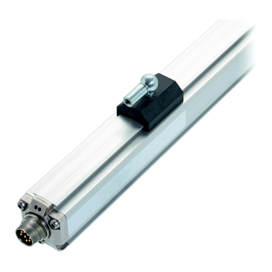
- Page 149 带绝缘套和 ISO 4762 M5x22 圆柱头螺钉 的安装夹具,最大紧固扭矩 2 Nm 1) 不可用区域 BTL7-...-S115 BTL7... 电缆 2) 未包含在交货范围内 13.8 max. 7 BTL7...,结构 图 3-1: 3.1 结构 电气连接:通过电缆或插头进行电气连接(参见第 25 页 上的“型号代码”)。 外壳:铝外壳,内含波导管和电子处理装置。 磁体:定义在波导管上测量的位置。磁体有不同的型号, 必须单独订购(参见第 21 页开始的附件)。 额定长度:为了最佳适应 BTL 的应用,可提供从 50 mm 至 7620 mm 的额定长度。 www.balluff.com 中文...
- Page 150 BTL7-S5_ _(B) -M _ _ _ _ -P-S32/S115/S147/KA_ _/FA_ _ 磁致伸缩线性位置传感器 - 外置式 结构和功能(接上页) LED 1 3.2 功能 绿色 正常功能 BTL 包含由铝制外壳保护的波导管。磁环沿着波导管移 磁块在工作范围内。 动。磁环连接到需要确定其位置的系统零件。 红色 错误 没有磁块,或磁块超出极限。 磁环定义在波导管上测量的位置。 内部产生的 INIT 脉冲与磁体的磁场相互作用,在波导管中 LED 2 产生以超声波速度传播的扭转波。 绿色 同步运行 内部测量与 SSI 查询同步。 到达波导管末端的扭波分量被吸收到阻尼区,以免反射。 熄灭 异步运行 到达波导管开头的扭波分量由一个线圈转换为电信号。波 内部测量与 SSI 查询异步。 的传播时间用于计算在 RS-422 接口上以反效形式作为同 步串行数据...
- Page 151 图 4-1: 扭矩拧紧夹具的螺钉)。 3. 插入磁体(附件)。 型材外壳中的 BTL 适用于浮动式(即,非接触 式磁体)(参见图 4-4 图 4-8)和引导式磁体 (参见图 4-1 至图 4-3)。 BTL5-T-2814-1S 磁环的尺寸和距离 图 4-2: BTL5-M/N-2814-1S 磁体的尺寸和距离 图 4-3: BTL5-M-2814-1S BTL5-N-2814-1S 48.5 mm 57 mm 距离 X 距离 Y 51 mm 59.5 mm 与 BTL5-M/N-2814-1S 磁体的距离 表 4-1: www.balluff.com 中文...
- Page 152 BTL7-S5_ _(B) -M _ _ _ _ -P-S32/S115/S147/KA_ _/FA_ _ 磁致伸缩线性位置传感器 - 外置式 安装和连接(接上页) 4.3 浮子定位磁块 安装磁环时,必须遵循下列事项: – 为了确保位置测量系统的精度,磁体使用非磁性螺钉 (不锈钢、黄铜、铝)固定到机器的运动件。 – 运动构件必须在平行于 BTL 的轨迹上引导磁体。 – 确 保 磁 体 与 可 磁 化 材 质 部 件 之 间 的 距 离 A 至 少 为 10 mm(参见图...
- Page 153 BTL7 标准 BTL7-S5_ _-…-S147 针 BTL7-S5_ _B-...-S147 –数据 S32 的针脚分配(BTL 的俯视图),8 针 M16 环形插头 +数据 图 4-9: +Clk –Clk 10…30 V 电源 0 V 未使用 未分配的导线可以连接到控制器上的 GND(接地),但不能连接到屏 蔽线。 接口分配 BTL7...-S147 表 4-5: 图 4-11: S147 的针脚分配(BTL 的俯视图),7 针 M16 环形插头 www.balluff.com 中文...
- Page 154 BTL7-S5_ _(B) -M _ _ _ _ -P-S32/S115/S147/KA_ _/FA_ _ 磁致伸缩线性位置传感器 - 外置式 安装和连接(接上页) 4.4.4 电缆连接 屏蔽和电缆布线 BTL7 标准 BTL7 USB 可配置 定义的接地! BTL 和控制柜必须处于相同的接地电位。 BTL7-S5_ _-...-KA/FA BTL7-S510-...-KA/FA 接线颜色 BTL7-S5_ _B-...-KA/FA BTL7-S510B-...-KA/FA 屏蔽端 YE 黄色 +Clk +Clk 为了确保电磁兼容性 (EMC),请遵循下列事项: GY 灰色 +数据 +数据 – 用屏蔽电缆连接 BTL 和控制器。 PK 粉色...
- Page 155 磁致伸缩线性位置传感器 - 外置式 启动 5.1 启动系统 危险 不受控制的系统移动 启动时,如果位置测量系统是尚未设置参数的闭环系统的 一部分,该系统可能执行不受控制的移动。这可能导致人 身伤害和设备损坏。 ► 人员必须远离系统的危险区域。 ► 必须由受过培训的技术人员执行启动。 ► 遵循设备或系统制造商的设备安全须知。 1. 检查接头紧固性和极性是否正确。更换损坏的接头。 2. 接通系统电源。 3. 检查测得的数值和可调参数,并视需要重新调节 BTL。 检查零点和终点的正确数值,尤其是更换 BTL 后或由制造商维修后。 5.2 操作注意事项 – 定期检查 BTL 和所有相关组件的功能。 – 出现故障时停止运行 BTL。 – 固定该系统,防止有人擅自操作。 www.balluff.com 中文...
- Page 156 BTL7-S5_ _(B) -M _ _ _ _ -P-S32/S115/S147/KA_ _/FA_ _ 磁致伸缩线性位置传感器 - 外置式 SSI 接口 使用 BTL7-S_ _B-M... 时,确定位置数据,然后及时输 6.1 原理 出,并与外部采样周期同步。对于同步运行,采样周期 T SSI 代表同步串行端口,使用差异时钟线和差异数据线描 必须在 T ≤ T ≤ 16 ms 的范围内。如果最小采样时 A,min 述数字同步接口。 间削弱,BTL 多次输出同样的位置数值。外部采样率大于 使用第一条下降循环边,要输出的数据文字在 BTL 中缓 内部采样率。此外,T 必须足够长,以便下一个时钟包不 冲,以确保数据一致性。数据输出在第一个上升循环侧发 会出现在前一个包的 t 范围内。 生,即,对于每条上升循环边,BTL 向数据行提供一个数...
- Page 157 部会发生一个 T 事件,数据输出切换到低电平,然后在 > n → T 事件 经过时间 t 后又回到高电平。保持高电平,直至下一个时 < n → T 事件 钟猝发。时间 t 在时间 t 结束后开始。 – SSI 时钟频率过低 f < 9.771 kHz → T 事件 两个时钟包之间的暂停太短 → T – 高频 事件 如果有太多的时钟边沿,在完成正确数量的循环后,数据 输出将切换为低电平。对于来自 Clk 的每个附加下降沿, 定时器都会再次启动,并且在内部设置 T 事件。经过 时间 t 后,数据切换回高电平。 www.balluff.com 中文...
- Page 158 BTL7-S5_ _(B) -M _ _ _ _ -P-S32/S115/S147/KA_ _/FA_ _ 磁致伸缩线性位置传感器 - 外置式 SSI 接口(接上页) 6.4 同步和异步运行 在同步运行期间,必须考虑两个边界条件: – 外部采样频率 f 必须在 62.5 Hz < f < f 范围内。 同步运行 A,max 最大允许采样频率 f 如第 20 页图 8-1 所示。 A,max 在控制应用中,通常需要统一但短暂的计时。位置延迟 t – 采样频率必须尽可能保持恒定。 必须保持尽可能短且恒定。因此,同步运行适用于闭环控 制。这里,内部的传感循环自行调整为外部采样循环。 采样频率是两个时钟包之间的倒数值,不能与 SSI 下图阐释这一关系: 时钟频率相混淆。 数据 外部采样点...
- Page 159 – 位置:在测量范围内的位置。 – 可以重置为出厂设置 – 速度:磁体的速度;符号显示移动方向。从起点移动 – 没有连接 BTL 的演示模式 到终点使用正号输出;从终点移动到起点则使用负号 输出。 – 速度(不带符号):磁体的速度,不能读取移动方向。 可以从互联网上获得电脑软件和相关的手册, – 差异位置:两个磁体之间的距离。只有选择两个磁环 网址为 www.balluff.com。 时,才能选择。 – 速度差:两个磁体的速度相减,构成一个数字。只有 选择两个磁环时,才能选择。 连接至 USB 通讯盒 7.2 可以自由配置的曲线 对于带连接器的 BTL,必须在 BTL 和控制器之间插入通信 – 可以通过调整分辨率设置特征曲线的梯度。 盒。可以通过 USB 电缆,将通讯盒连接至 PC 机。 –...
- Page 160 BTL7-S5_ _(B) -M _ _ _ _ -P-S32/S115/S147/KA_ _/FA_ _ 磁致伸缩线性位置传感器 - 外置式 技术数据 8.1 精度 8.3 供电电压 规格是在 24 V DC 和室温下,额定长度为 500 mm,与 10…30 V DC 电压,稳定 BTL5-P-3800-2、BTL5-P-4500-1、BTL5-P-5500-2 、 纹波 ≤ 0.5 V BTL6-A-3800-2 、BTL6-A-3801-2 、BTL5-F-2814-1S、 BTL5-T-2814-1S、BTL5-M-2814-1S 或 BTL5-N-2814-1S 电流消耗(24 V DC 时) ≤ 100 mA 磁体配合使用时的 BTL7-S... 的典型值。 浪涌电流 ≤ 500 mA BTL 在预热后,立即可以使用最高精度正常工作。 最高...
- Page 161 外壳高度 50…7620 mm 额定检测长度 重量(取决于长度) 约 1.4 kg/m 外壳材质 铝 BTL7-...-KA_ _ 电缆材料 cULus 20549 80 °C,300 V, 内部接线 –40…+90°C 电缆温度 最大 7 mm 电缆直径 允许的弯曲半径 布线 ≥ 35 mm 已移动 ≥ 105 mm BTL7-...-FA_ _ PTFE 电缆材料 无 UL 认证 –55…+200°C 电缆温度 最大 7 mm 电缆直径 允许的弯曲半径 布线 ≥ 35 mm 已移动 不允许弯曲 www.balluff.com 中文...
- Page 162 BTL7-S5_ _(B) -M _ _ _ _ -P-S32/S115/S147/KA_ _/FA_ _ 磁致伸缩线性位置传感器 - 外置式 技术数据(接上页) 8.7 与估算单元的连接 在最大采样频率 f 最小采样频率 f 为 62.5 Hz。 下,每次采样可提供新的当前值, A,max A,min 该频率可参见下图: (Hz) A,max (1) 1 个磁体 (2) 2 个磁体 (仅限 BTL7-S510 (B)-...) 额定长度,mm 图 8-1: 最大采样率取决于额定长度(对于位置输出)速度输出的 最大采样率限制为 3.3 kHz。 最大 SSI 时钟频率 f 取决于电缆长度...
- Page 163 重量: 订购时,请注明额定长度 外壳: 铝 铝 滑动表面: 塑料 塑料 样例:BTL2-GS10-0100-A(额定长度 = 100 mm) BTL5-F-2814-1S M5x10 BTL5-F-2814-1S 磁环安装尺寸 图 9-2: 大约 28 g 重量: 外壳: 铝 滑动表面: 塑料 BTL5-T-2814-1S BTL5-T-2814-1S 磁环安装尺寸 图 9-3: 大约 28 g 重量: 外壳: 铝 滑动表面: 塑料 www.balluff.com 中文...
- Page 164 BTL7-S5_ _(B) -M _ _ _ _ -P-S32/S115/S147/KA_ _/FA_ _ 磁致伸缩线性位置传感器 - 外置式 附件(接上页) BTL6-A-3801-2 9.3 浮子定位磁块 37.6 BTL5-P-3800-2 Ø 4.2 Ø 4.2 BTL6-A-3801-2 磁环安装尺寸 图 9-8: 大约 25 g 重量: BTL5-P-3800-2 磁环安装尺寸 图 9-5: 外壳: 塑料 大约 12 g 重量: BTL5-P-4500-1 外壳: 塑料 BTL5-P-5500-2 M5x8 Ø 4.5 Ø...
- Page 165 弯头插头,M16,根据 IEC 130-9,8 针 ~ 54 48.5 连接器型号 S32(预组装) 图 9-13: 针 颜色 Ø 20 YE 黄色 连接器 BKS S 33M-00 图 9-11: GY 灰色 PK 粉色 RD 红色 GN 绿色 BU 蓝色 BN 棕色 WH 白色 S32(预组装)针脚分配 表 9-1: www.balluff.com 中文...
- Page 166 BTL7-S5_ _(B) -M _ _ _ _ -P-S32/S115/S147/KA_ _/FA_ _ 磁致伸缩线性位置传感器 - 外置式 附件(接上页) 连接器型号 S115,预组装 USB 通讯盒 9.5 BKS-S115-PU-_ _ BTL7-A-CB01-USB-S32 用于带连接器型号 S32 的 BTL7-S510 (B)-...。 直头插头,模制电缆,M12,8 针 可以订购各种长度的电缆,例如 BKS-S115-PU-05(订购 供货清单:USB 通信盒,USB 电缆线,2 根适配器电缆, 代码:BCC00YF):电缆长度 5 m 每根大约 0.3 m 长,简易指南。 BTL7-A-CB01-USB-S115 用于带连接器型号 S115 的 BTL7-S510 (B)-...。 供货清单:USB 通信盒,USB 电缆线,2 根适配器电缆,...
- Page 167 额定长度(4 位): M0500 = 以 mm 为单位的公制规格,额定长度 500 mm (M0050…M7620) 结构: P = 型材外壳 电气连接: S32 = 8 针,M16 插头,符合 IEC 130-9 S115 = 8 针,M12 插头 S147 = 7 针,M16 插头,符合 DIN 45329 KA05 = 电缆,5 m (PUR) FA05 = 电缆,5 m (PTFE) www.balluff.com 中文...
- Page 168 BTL7-S5_ _(B) -M _ _ _ _ -P-S32/S115/S147/KA_ _/FA_ _ 磁致伸缩线性位置传感器 - 外置式 型号代码分解(接上页) BTL7 USB 可配置 BTL7 - S 5 1 0 B - M0500 - P - S32 SSI 接口 供电电压: 5 = 10…30 V DC 数据格式: 1 = 24 位,格雷码,上升(出厂设置) 分辨率: 0 = 1 µm(出厂设置) 同步/异步运行: B = 同步运行 无...
- Page 169 英寸 0.03937008 25.4 0.07874016 50.8 0.11811024 76.2 0.15748031 101.6 0.19685039 0.23622047 152.4 0.27559055 177.8 0.31496063 203.2 0.35433071 228.6 0.393700787 表 11-1: mm 英寸换算表 表 11-2: 英寸 mm 换算表 11.2 零件标签 订购代码 类型 序列号 零点标记 图 11-1: BTL7 零件标签(样例) www.balluff.com 中文...
- Page 171 BTL7-S5_ _(B) -M _ _ _ _-P-S32/S115/S147/KA_ _/FA_ _ 사용자 가이드 한국어...
- Page 172 www.balluff.com...
- Page 173 잘못된 SSI 쿼리 동기 및 비동기 작동 BTL7 구성 도구를 사용한 구성 BTL7 구성 도구 USB 통신 박스 연결 구성 옵션 기술 자료 정확도 주변 조건 공급 전압 출력 통신 회선 La, Lb 치수, 무게 평가 장치 연결 www.balluff.com 한국어...
- Page 174 BTL7-S5_ _(B) -M _ _ _ _-P-S32/S115/S147/KA_ _/FA_ _ 자기 변형 선형 위치 센서 – 프로파일 스타일 액세서리 부동 자석 BTL2-GS10-_ _ _ _-A 조인트 로드 유동 자석 커넥터 유형 S32 9.4.1 자유롭게 구성 가능 9.4.2 사전 조립됨 커넥터 유형 S115, 사전 조립됨 USB 통신...
- Page 175 지침, 승인 및 표준에 관한 보다 상세한 정보는 적합성 선언을 확인하십시오. 자석은 다양한 모델로 제공되며 별도 주문해야 합니다. 약어 승인 및 표시 동기 직렬 인터페이스 BTL7-…-FA_ _용이 아님 US Patent 5 9231 64 이 제품과 관련하여 미국 특허를 받았습니다. www.balluff.com 한국어...
- Page 176 BTL7-S5_ _(B) -M _ _ _ _-P-S32/S115/S147/KA_ _/FA_ _ 자기 변형 선형 위치 센서 – 프로파일 스타일 안전 용도 경고에 대한 설명 BTL 자기 변형 선형 위치 센서는 기계 컨트롤러(예: PLC)와 위험을 방지하기 위해서는 항상 지침에 제시된 경고 및 함께 위치 측정 시스템을 구성합니다. 기계나 시스템에 조치를...
- Page 177 하우징: 도파관 및 처리 전자 장치가 포함된 알루미늄 하우징. 자석: 도파관에서 측정할 위치를 정의합니다. 자석은 다양한 모델로 제공되며 별도로 주문해야 합니다 (21페이지의 부속품 참조). 공칭 길이: BTL을 응용 목적에 따라 최적으로 적용하기 위해, 50 mm ~ 7620 mm의 공칭 길이를 사용합니다. www.balluff.com 한국어...
- Page 178 BTL7-S5_ _(B) -M _ _ _ _-P-S32/S115/S147/KA_ _/FA_ _ 자기 변형 선형 위치 센서 – 프로파일 스타일 구성 및 기능(계속) LED 1 기능 녹색 정상 기능 BTL에는 알루미늄 하우징으로 보호된 도파선이 자석이 측정범위 내에 있음. 포함됩니다. 자석은 이 도파관을 따라 움직입니다. 이...
- Page 179 그림 4-2: BTL5-T-2814-1S 자석 사용 시 치수 및 거리 그림 4-3: BTL5-M/N-2814-1S 자석 사용 시 치수 및 거리 BTL5-M-2814-1S BTL5-N-2814-1S 48.5 mm 57 mm 거리 X 거리 Y 51 mm 59.5 mm 표 4-1: BTL5-M/N-2814-1S 자석 사용 시 거리 www.balluff.com 한국어...
- Page 180 BTL7-S5_ _(B) -M _ _ _ _-P-S32/S115/S147/KA_ _/FA_ _ 자기 변형 선형 위치 센서 – 프로파일 스타일 설치 및 연결(계속) 유동 자석 자석 설치 시에는 다음을 반드시 준수해야 합니다. – 위치 측정 시스템의 정확성을 위해, 기계의 이동 부재에는 자기화되지 않는 나사(스테인리스강, 황동, 알루미늄)를...
- Page 181 그림 4-9: S32 핀 할당(BTL 위에서 볼 경우), 8핀 M16 원형 플러그 –Clk 10…30 V 접지 사용하지 않음 미할당 리드는 컨트롤러 측 GND에 연결 가능하나 실드에는 연결 불가함. 표 4-5: 연결 할당 BTL7…-S147 그림 4-11: S147 핀 할당(BTL 위에서 볼 경우), 7핀 M16 원형 플러그 www.balluff.com 한국어...
- Page 182 BTL7-S5_ _(B) -M _ _ _ _-P-S32/S115/S147/KA_ _/FA_ _ 자기 변형 선형 위치 센서 – 프로파일 스타일 설치 및 연결(계속) 4.4.4 케이블 연결 차폐 및 케이블 배선 BTL7 표준 BTL7 USB 정의된 접지! BTL과 제어 캐비닛은 반드시 동일한 접지 구성 가능 퍼텐셜에...
- Page 183 경우 BTL을 다시 조정하십시오. 특히 BTL 교체 또는 제조업체의 수리 작업 후, 영점과 끝점에서 값이 정확한지 점검하십시오. 운영 참고 사항 – BTL과 모든 관련 구성품의 기능을 정기적으로 점검하십시오. – 오작동 발생 시 BTL의 작동을 중단하십시오. – 시스템의 무단 사용을 방지하십시오. www.balluff.com 한국어...
- Page 184 BTL7-S5_ _(B) -M _ _ _ _-P-S32/S115/S147/KA_ _/FA_ _ 자기 변형 선형 위치 센서 – 프로파일 스타일 SSI 인터페이스 BTL7-S_ _B-M…을 통해 위치 데이터가 결정되며 적시에 원리 외부 샘플링 기간과 동기화되어 출력됩니다. 동기 작동의 SSI는 동기 직렬 인터페이스(Synchronous Serial Interface)의 경우...
- Page 185 두 클럭 패키지 사이의 휴지가 너무 짧은 경우. 클럭 끝 신호가 너무 많을 경우, 정확한 수의 사이클이 → T 이벤트 완료된 후 데이터 출력이 낮게 전환됩니다. t 타이머가 Clk의 추가 음(-)의 끝마다 다시 시작되며 T 이벤트가 내부적으로 설정됩니다. 시간t 이 지나면 데이터가 다시 높게 전환됩니다. www.balluff.com 한국어...
- Page 186 BTL7-S5_ _(B) -M _ _ _ _-P-S32/S115/S147/KA_ _/FA_ _ 자기 변형 선형 위치 센서 – 프로파일 스타일 SSI 인터페이스(계속) 동기 및 비동기 작동 동기 작동 중에는 두 가지 경계 조건을 고려해야 합니다. – 외부 샘플링 주파수 f 는 62.5 Hz < f <...
- Page 187 출력됩니다. 끝점에서 시작점으로의 이동은 음의 부호로 출력됩니다. PC 소프트웨어 및 관련 매뉴얼은 – 속도(부호 없음): 자석의 속도. 이동 방향을 파악할 수 www.balluff.com에서 확인할 수 있습니다. 없습니다. – 차동 위치: 두 자석 사이의 거리. 두 개의 자석이 선택된 경우에만 선택 가능합니다.
- Page 188 공칭 길이 = 500 mm, 측정 범위 중간에 자석이 있을 경우 < 90%(비응축) 습도 UL의 경우: 밀폐 공간 및 해발 최대 2000 m까지 사용함. 150 g/6 ms 충격 등급 Balluff 공장 표준에 따른 개별 사양 150 g/2 ms EN 60068-2-27 4), 5) 에 R공진 주파수 제외...
- Page 189 고정 경로 ≥ 105 mm 유동 경로 BTL7-...-FA_ _ PTFE 케이블 소재 해당 UL 승인 없음 –55…+200°C 케이블 온도 최대 7 mm 케이블 지름 허용 곡률 반경 ≥ 35 mm 고정 경로 유동 경로 허용되는 곡률 반경 없음 www.balluff.com 한국어...
- Page 190 BTL7-S5_ _(B) -M _ _ _ _-P-S32/S115/S147/KA_ _/FA_ _ 자기 변형 선형 위치 센서 – 프로파일 스타일 기술 자료(계속) 평가 장치 연결 최소 샘플링 주파수 f 는 62.5 Hz입니다. 각 샘플링에 하나의 새로운 전류 값을 제공하는 최대 A,min 샘플링 주파수 f 는...
- Page 191 예시: BTL2-GS10-0100-A (공칭 길이 = 100 mm) 표면: BTL5-F-2814-1S M5x10 그림 9-2: BTL5-F-2814-1S 자석의 설치 치수 약 28 g 중량: 하우징: 알루미늄 슬라이드 표면: 플라스틱 BTL5-T-2814-1S 그림 9-3: BTL5-T-2814-1S 자석의 설치 치수 약 28 g 중량: 하우징: 알루미늄 슬라이드 표면: 플라스틱 www.balluff.com 한국어...
- Page 192 BTL7-S5_ _(B) -M _ _ _ _-P-S32/S115/S147/KA_ _/FA_ _ 자기 변형 선형 위치 센서 – 프로파일 스타일 부속품(계속) BTL6-A-3801-2 유동 자석 37.6 BTL5-P-3800-2 Ø 4.2 Ø 4.2 그림 9-8: BTL6-A-3801-2 자석의 설치 치수 약 25 g 중량: 그림 9-5: BTL5-P-3800-2 자석의 설치 치수 하우징: 플라스틱...
- Page 193 ~ 54 48.5 커넥터 유형 S32(사전 조립됨) 그림 9-13: 핀 색상 Ø 20 YE 노란색 커넥터 BKS-S33M-00 그림 9-11: GY 회색 PK 분홍색 RD 빨간색 GN 초록색 BU 파란색 BN 갈색 WH 흰색 표 9-1: S32(사전조립) 핀 할당 www.balluff.com 한국어...
- Page 194 BTL7-S5_ _(B) -M _ _ _ _-P-S32/S115/S147/KA_ _/FA_ _ 자기 변형 선형 위치 센서 – 프로파일 스타일 부속품(계속) 커넥터 유형 S115, 단방향 코드 USB 통신 박스 BKS-S115-PU-_ _ BTL7-A-CB01-USB-S32 직선형 커넥터, 성형 케이블, M12, 8핀 BTL7-S510(B)-…(커넥터 유형 S32)용. 다양한 케이블 길이로 주문 가능. 예: BKS-S115-PU-05 제공...
- Page 195 M0500 = 미터법 사양(단위: mm), 공칭 길이 500 mm(M0050…M7620) 구성: P = 프로파일 하우징 전기적 연결: S32 = 8핀, M16 플러그(IEC 130-9에 따름) S115 = 8핀, M12 플러그 S147 = 7핀, M16 플러그(DIN 45329에 따름) KA05 = 케이블, 5 m(PUR) FA05 = 케이블, 5 m(PTFE) www.balluff.com 한국어...
- Page 196 BTL7-S5_ _(B) -M _ _ _ _-P-S32/S115/S147/KA_ _/FA_ _ 자기 변형 선형 위치 센서 – 프로파일 스타일 유형 코드 분류(계속) BTL7 USB 구성 가능 BTL7 - S 5 1 0 B - M0500 - P - S32 SSI 인터페이스 공급 전압: 5 = 10…30 V DC 데이터...
- Page 197 0.11811024 76.2 0.15748031 101.6 0.19685039 0.23622047 152.4 0.27559055 177.8 0.31496063 203.2 0.35433071 228.6 0.393700787 표 11-2: 변환 테이블(인치에서 mm로) 표 11-1: 변환 테이블(mm에서 인치로) 11.2 부품 라벨 주문 코드 유형 일련번호 영점 표시 그림 11-1: BTL7 부품 라벨(예시) www.balluff.com 한국어...
- Page 198 Technical Service Hub Technical Service Hub Region EMEA Region APAC Region Americas Balluff GmbH Balluff Automation (Shanghai) Co., Ltd. Balluff Inc. Schurwaldstrasse 9 No. 800 Chengshan Rd, 8F, Buidling A, 8125 Holton Drive 73765 Neuhausen a.d.F. Yunding International Commercial Plaza...
Need help?
Do you have a question about the BTL7-S5 (B) M P S32/S115/S147/KA FA Series and is the answer not in the manual?
Questions and answers