Advertisement
Available languages
Available languages
Quick Links
Advertisement

Related Manuals for Balluff BVS ID-M1280 F1 Series


Summary of Contents for Balluff BVS ID-M1280 F1 Series
- Page 1 BVS ID-M1280xF1-xx-xxx deutsch Konfigurationsanleitung Configuration Guide english...
- Page 2 www.balluff.com...
- Page 3 BVS ID-M1280xF1-xx-xxx deutsch Konfigurationsanleitung...
- Page 4 www.balluff.com...
- Page 5 Inputs ................26 2.4.2 Analysis ................30 2.4.3 Outputs ................38 2.4.4 Laufzeitoptimierungen der Inspektionsdurchläufe ....41 Geräte-Infos 42 Balluff Engineering Tool (BET) 43 Einleitung 43 3.1.1 Software installieren ............43 3.1.2 Topologie einrichten ............44 Anbindung an das Kundensteuerungssystem 48 UDP/TCP Prozessdatenprotokoll 48...
- Page 6 BVS ID-M1280xF1-xx-xxx 4.1.1 Einleitung ................. 48 4.1.2 Ablauf der Kommunikation..........49 4.1.3 Aufbau einer Nachricht............49 4.1.4 Ereignisnachrichten vom BVS ID.......... 52 4.1.5 Aktionsnachrichten an den BVS ID ........56 4.1.6 Kommunikation testen............65 Kommunikation über REST API 66 4.2.1 Einleitung .................
- Page 7 Dokumente vollständig, bevor Sie das Produkt installieren und betreiben. Diese Anleitung wurde in Deutsch erstellt. Andere Sprachversionen sind Übersetzungen dieser Anleitung. © Copyright 2022, Balluff GmbH Alle Inhalte sind urheberrechtlich geschützt. Alle Rechte, einschließlich der Vervielfältigung, Veröffentlichung,...
- Page 8 BVS ID-M1280xF1-xx-xxx 1.2.6 Zeichenkodierung Allgemeines Bei der BVS ID Konfiguration sind Zeichenketten UTF-8-kodiert anzugeben. Die ersten 128 Zeichen des Unicode Zeichensatzes sind deckungsgleich mit ASCII, d.h. ein ASCII kodierter Text und dessen UTF-8 Kodierung haben immer dieselbe Binärrepräsentation. Bestehen alle eingegebenen Zeichenketten nur aus ASCII-Werten kleiner 128, so sind diese Zeichenketten automatisch UTF-8 kodiert.
- Page 9 BVS ID-M1280xF1-xx-xxx Verwendete Fachbegriffe und Abkürzungen Area of interest (Bildausschnitt) Balluff Vision Solutions CMOS Complementary metal-oxide-semiconductor DHCP Dynamic Host Configuration Protocol E/A-Port Digitaler Eingang- bzw. Ausgangsport EEPROM Electrical Erasable and Programmable ROM Elektromagnetische Verträglichkeit Federal Communications Commission Ground / Masse...
- Page 10 Die Balluff GmbH ist berechtigt – aber nicht verpflichtet – Updates oder Upgrades der Firmware über die Website der Balluff GmbH oder in jeder anderen Form zur Verfügung zu stellen. In solch einem Fall ist die Balluff GmbH berechtigt – aber nicht verpflichtet – Sie über die Updates oder Upgrades zu informieren. Die Inanspruchnahme solcher Upgrades oder Updates setzt voraus, dass Sie die Geltung die aktuellen AGB sowie die zusätzlichen Bedingungen in dem Bedienungshandbuch akzeptiert haben.
- Page 11 BVS ID-M1280xF1-xx-xxx SensorApp / Webinterface Einleitung Im Normalfall wird die BVS ID per Auto-Setup-Prozess konfiguriert. Jedoch hat der Betreiber die Möglichkeit, über das Webinterface ("SensorApp") die Sensorkonfiguration anzupassen, Live-Bilder darzustellen, Statistiken anzuschauen und Systemeinstellungen zu ändern. Systemstatus und Systemfehler einzusehen. Führen sie folgende Aktionen aus: Öffnen Sie einen Webbrowser.
- Page 12 BVS ID-M1280xF1-xx-xxx 2.1.1 Die SensorApp-Oberfläche Nummer Name Bedeutung Systemmenü Für die Anpassung systemrelevanter Einstellungen wie Netzwerkverhalten, Kommunikation, etc. Aktionsmenü Für das Konfigurieren und Monitoring der Inspektion Ergebnistabelle Für die Anzeige der Inspektionsergebnisse Live-Bild Für die Anzeige des Live-Bildes Geräte-Info Für die Anzeige von Geräte-Infos, Status und Fehlern. Systemmenü...
- Page 13 Es existieren drei Arten von Log-Dateien: System Log-Dateien (system.log): Diese Log-Dateien enthalten Berichte über schwerwiegende Fehler sowie Abstürze und könnten Balluff-Entwicklern in der Suche nach der Fehlerursache unterstützen. Client Log-Dateien (client.log): Diese Log-Dateien enthalten Berichte über Ereignisse und Fehler in Webbrowsern, über welche die SensorApp bedient wird.
- Page 14 BVS ID-M1280xF1-xx-xxx HINWEIS Für den Zugriff auf dieses Verzeichnis müssen sie folgende Login-Daten eingeben: • Login: expert • Passwort: expert Sensor Clock Hier können die Einstellungen bzgl. Systemdatum und -zeit getätigt werden. Einstellung Beschreibung Bestimmt, ob die Systemzeit von einem externen Zeitserver geholt werden soll. ...
- Page 15 BVS ID-M1280xF1-xx-xxx 2.2.2.2 IIOT Network Hier können alle Netzwerkeinstellungen des BVS ID angepasst werden. Damit die Änderungen wirksam werden, muss der BVS ID neu gestartet werden. HINWEIS Um nach der Änderung der Netzwerkeinstellungen mit dem BVS ID verbinden zu können, muss der BVS ID an ein entsprechendes Netzwerk gemäß...
- Page 16 BVS ID-M1280xF1-xx-xxx Einstellung Beschreibung Falls eine statische IP-Adresse verwendet werden soll, kann hier der Gateway eingetragen werden. Wenn nur vom gleichen Subnetz auf die Kamera zugegriffen werden soll, ist die Eingabe optional. HINWEIS Gateway Das Gateway gibt an, wie Pakete zu anderen Netzwerken geroutet werden. Auch wenn beide Netzwerkschnittstellen aktiv sind, sollte in der Regel nur ein Gateway eingetragen werden.
- Page 17 BVS ID-M1280xF1-xx-xxx 2.2.2.3 Process Communication Im Bereich Kommunikation kann eingestellt werden, wie mit angeschlossenen Geräten wie SPS oder Steuer- PCs kommuniziert wird. Einstellung Beschreibung Die zu verwendende Kommunikationsschnittstelle: • IO-Link Protokoll • • • REST-OT IO-Link-Status [IO-Link] Zeigt an, ob es eine aktive Verbindung zu einem IO-Link-Master gibt oder nicht. Byte-Reihenfolge von Nachrichtenelementen, die aus mehr als einem Byte bestehen: IO-Link-Endianness [IO-Link] •...
- Page 18 BVS ID-M1280xF1-xx-xxx MQTT Einstellung Beschreibung Enabled Aktiviert das Senden der erfassten Daten an den angegebenen MQTT-Broker. Folgende MQTT-Verbindungsmodi stehen zur Verfügung: • MQTT • MQTT verschlüsselt ohne CA-Datei (unsicher) Es handelt sich hierbei um eine verschlüsselte Verbindung ohne Authentizitätsprüfung Mode des Brokers. •...
- Page 19 BVS ID-M1280xF1-xx-xxx 2.2.2.4 IIOT Reports Hier kann eingestellt werden, welche Ergebnisse die Berichte enthalten sollen und auf welchem Speicherort die Berichte abgelegt werden. Die exportierten Berichte werden je nach ausgewähltem Protokoll als XML-Dateien auf dem Server, oder im angegebenen Verzeichnis unter einem Ordner mit dem Namen des Inspektionsprogramms abgelegt. Die XML- Dateien können mit einem Browser geöffnet und visualisiert werden.
- Page 20 BVS ID-M1280xF1-xx-xxx HINWEIS Für das Einrichten eines Servers oder einer Netzwerkfreigabe zur Aufnahme der Berichte konsultieren Sie bitte Ihre IT-Abteilung oder externe Quellen. Standard reports Standardberichte werden nach jedem Inspektionsdurchlauf erstellt, falls mindestens eine der Optionen aus der untenstehenden Tabelle aktiviert ist und ein entsprechendes Inspektionsergebnis (OK/NOK) vorliegt. Einstellung Beschreibung OK Inspektionsergebnisse...
- Page 21 BVS ID-M1280xF1-xx-xxx 2.2.2.5 Sicherheit Hier kann die Zugriffskontrolle zur SensorApp eingestellt werden. Normalerweise ist die Zugriffskontrolle aktiviert und kann mit DISABLE abgeschaltet werden. Der "admin"- Benutzer kann alle Passwörter editieren. Eine Änderung muss mit SET bestätigt werden (kein automatisches Speichern). Wenn die Zugriffskontrolle abgeschaltet ist, kann diese mit ENABLE angeschaltet werden. Weiterhin kann hier eingestellt werden, wie der Browser sich mit der SensorApp verbindet.
- Page 22 BVS ID-M1280xF1-xx-xxx Dieser Dialog wird immer angezeigt, solange eines der Passwörter leer ist. Um ohne Passwortvergabe fortzufahren, kann die Benutzerverwaltung in diesem Dialog auch dauerhaft abgeschaltet werden. Benutzerrechte Die SensorApp bietet folgende Benutzer mit den zugehörigen Berechtigungen für die GUI an: Deaktiviert Aktiviert Nicht...
- Page 23 BVS ID-M1280xF1-xx-xxx 2.2.3 Benutzerinformationen und Spracheinstellungen In diesem Bereich wird angezeigt, welcher Benutzer angemeldet ist. Hier kann der Benutzer auch abgemeldet werden. Des Weiteren wird die Systemsprache angezeigt. deutsch ...
- Page 24 BVS ID-M1280xF1-xx-xxx Aktionsmenü Das Aktionsmenü bietet zwei Aktionsbereiche: • Configure erlaubt die Erstellung und Verwaltung von Inspektionsprogrammen. • Monitor stellt die Prüfergebnisse dar. Dies ist auch die Standardseite, die automatisch beim Verbinden angezeigt wird. In diesem Modus können keine Systemeinstellungen geändert werden. Der BVS ID öffnet beim Start das zuletzt geöffnete Inspektionsprogramm im Monitor-Modus.
- Page 25 BVS ID-M1280xF1-xx-xxx 2.3.1.1 Übersicht über Inspektionsergebnisse Die Tabelle zeigt die Liste der Inspektionsergebnisse an. Jedes Inspektionsergebnis besteht aus • Prüfergebnis, • Ergebnisnummer, • Gefundene Codes, • Datum der Bildaufnahme und • Ausführungszeit (die Ausführungszeit beinhaltet nicht die Zeit, welche für das Warten auf ein Trigger- Signal, die Belichtungszeit bei der Bildaufnahme oder zum Schreiben von Berichten auf einen Server anfallen) ...
- Page 26 BVS ID-M1280xF1-xx-xxx 2.3.2 Configure Über Configure erstellen Sie Inspektionsprogramme. Menüpunkt Bedeutung Das Programm nimmt kontinuierlich Bilder auf ("Schleife") und wird bis zum selektierten Programmschritt durchlaufen. Falls in Inputs der Trigger-Modus Rising edge gewählt wurde, wird auf ein Trigger-Ereignis gewartet. Wenn die Schleife aktiviert ist und auf ein Trigger-Ereignis gewartet wird, kann hiermit ein Trigger ausgelöst werden. Dieser führt zu einer Bildaufnahme.
- Page 27 BVS ID-M1280xF1-xx-xxx 2.3.2.1 Inspektionsprogramme speichern Werden Änderungen am Inspektionsprogramm vorgenommen, so werden diese nicht automatisch gespeichert. Stattdessen wird das Speichern-Symbol im Konfigurationsmodus farblich hervorgehoben, um zu signalisieren, dass ungespeicherte Änderungen vorliegen. Mit Betätigung des Speichern-Symbols werden alle Änderungen geschrieben und bleiben auch nach Stromverlust bestehen. ...
- Page 28 BVS ID-M1280xF1-xx-xxx Tools 2.4.1 Inputs Inputs besteht aus zwei Bereichen: External reference code Sensor device 2.4.1.1 Externe Parametrierung Aufgabe Hier wird der von der Datenschnittstelle empfangenen Datencontainer, welcher einen UTF-8-kodierten Referenzwert in beliebiger Länge enthalten kann, eingelesen. Der eingelesene Referenzwert kann mit dem gelesenen Code verglichen werden (siehe Abschnitt Analysis).
- Page 29 BVS ID-M1280xF1-xx-xxx Parameter Parameter Beschreibung Datentyp Aktiv Einlesen eines Referenzwertes aktivieren oder deaktivieren. Bool String Länge Zahl der Byte des einzulesenden Referenzwertes. Uint16 Neue Referenz pro Testzyklus aktiviert, so wird der Eingabepuffer, der den eingelesenen Referenzwert repräsentiert, nach Fertigstellung eines Inspektionsprogrammdurchlaufs gelöscht.
- Page 30 BVS ID-M1280xF1-xx-xxx 2.4.1.2 Sensor device Aufgabe Hier können der Sensor ausgewählt und die Sensorparameter eingestellt werden. Parameter Parameter Beschreibung Datentyp Auswahl einer Bildquelle. Die Simulation ("Image Files") dient zur Anzeige und Verarbeitung Bildquelle gespeicherter Bilder. • Continuous - Keine externe Triggerung aktiv. Der Sensor nimmt freilaufend Bilder auf.
- Page 31 BVS ID-M1280xF1-xx-xxx Parameter Beschreibung Datentyp Legt die Entfernung zwischen Vorderseite des Sensors und dem zu lesenden Code fest, auf welche der Fokus scharf gestellt werden soll (50 - 600 mm). HINWEIS Die Einstellung dieses Wertes sollte bei der normalen Umgebungstemperatur und bei betriebswarmem Gerät erfolgen.
- Page 32 BVS ID-M1280xF1-xx-xxx 2.4.2 Analysis Analysis besteht aus folgenden Bereichen: 1D Barcodes / 2D Barcodes General settings 2.4.2.1 1D Barcodes / 2D Barcodes Aufgabe Hier werden die Codes bestimmt, nach welchem das Tool suchen soll. Codes werden dabei innerhalb des Auswertebereichs gesucht und auch dann erkannt, wenn diese gedreht sind oder in unterschiedlicher Größe vorliegen.
- Page 33 BVS ID-M1280xF1-xx-xxx Parameter Beschreibung Datentyp Liste mit den Typen von Barcodes (1D), die im Bild gesucht werden. Alle anderen Barcodes werden bei der Suche ignoriert. HINWEIS Code-Typen 1D [Bool] Diese Auswahl wird bei einem erfolgreich durchlaufenen Auto-Setup-Prozess automatisch gesetzt. Die Codetypen "Pharma Code" und "MSI" werden durch den Auto-Setup-Prozess nicht unterstützt.
- Page 34 BVS ID-M1280xF1-xx-xxx HINWEIS Zur stabilen Dekodierung von 2D-Codes muss die Auflösung mindestens 4 Pixel pro Modul sein, für den Code-Typ PDF417 genügen 3 Pixel pro Modul. Für den kleinsten 2D-Code (Micro QR Code, der aus 11 Modulen besteht), ergibt sich damit eine Mindestgröße von 44 * 44 Pixeln. Referenzlagen 2D-Codes Aztec Code Datamatrix ECC 200...
- Page 35 BVS ID-M1280xF1-xx-xxx 2.4.2.2 General settings Aufgabe Hier werden die allgemeinen Einstellungen für das Tool vorgegeben. Parameter Parameter Beschreibung Datentyp Quelle des zu erwartenden Gibt an, welche Quelle für den zu erwartenden Wert verwendet werden soll. Wertes Die enthaltenen Werte aller Codes werden mit dem erwarteten Wert verglichen. Die Bildanalyse ist erfolgreich, wenn mindestens ein Code gefunden wurde, der den erwarteten Wert enthält.
- Page 36 BVS ID-M1280xF1-xx-xxx Parameter Beschreibung Datentyp Bestimmt das Kriterium, nach welchem die gefundenen Codes im Anschluss an die Codesuche sortiert werden. Sortiermodus Beschreibung Codes werden anhand der X-Koordinate des X-Position (links → rechts) Mittelpunktes von links nach rechts sortiert. Codes werden anhand der X-Koordinate des X-Position (rechts →...
- Page 37 BVS ID-M1280xF1-xx-xxx Code-Qualität Die Code-Qualität wird für 1D-Codetypen in Anlehnung an die Norm ISO/IEC 15416 berechnet. Für 2D- Codetypen kann mittels Qualität berechnen eine Berechnung in Anlehnung an ISO/IEC 15415 oder in Anlehnung an ISO/IEC TR 29158 gewählt werden. Für PDF417 wird nur ISO/IEC 15415 unterstützt. Beachten Sie, dass die Normen Anweisungen zu Messaufbau und Messdurchführung enthalten.
- Page 38 BVS ID-M1280xF1-xx-xxx Aufbau des Ergebnisstrings zur ermittelten Qualität von 2D-Codetypen in Anlehnung an ISO/IEC 15415 Die ermittelte Qualität wird dem Benutzer als String im Format a (bcdefghij) angezeigt und hat für alle Codes außer PDF417 folgende Bedeutung: Inde Merkmal (de) Merkmal (en) Beschreibung Gesamtqualität Overall quality...
- Page 39 BVS ID-M1280xF1-xx-xxx Aufbau des Ergebnisstrings zur ermittelten Qualität von 2D-Codetypen in Anlehnung an ISO/IEC TR 29158 Die ermittelte Qualität wird dem Benutzer als String im Format a (bcdefghij) angezeigt und hat für alle Codes folgende Bedeutung: Inde Merkmal (de) Merkmal (en) Beschreibung Gesamtqualität Overall quality...
- Page 40 BVS ID-M1280xF1-xx-xxx 2.4.3 Outputs 2.4.3.1 Aufgabe Dient dazu, Ergebnisse des Inspektionsprogramms zu versenden. In den globalen Einstellungen wird definiert, ob das Ergebnis über IO-Link oder über die Ethernet-Schnittstelle (TCP/IP bzw. UDP) an die Steuerung verschickt wird. Das Tool passt sich dynamisch an und bietet die Möglichkeit, zu definieren, welche Code- Informationen der gefundenen Ergebnisse über die konfigurierte Schnittstelle versendet werden.
- Page 41 BVS ID-M1280xF1-xx-xxx deutsch ...
- Page 42 BVS ID-M1280xF1-xx-xxx Standardlän Parameter Beschreibung Datentyp ge [Bytes] Total Result Das Gesamtergebnis eines Inspektionsdurchlaufs Bool Result Message String-Nachricht, die das Ergebnis des Durchlaufs beschreibt String Code Type 1...n Typbeschreibung des gefundenen Codes String Gelesener Text des gefundenen Codes - die Standardlänge wird bei erfolgreich Code Value 1...n String durchlaufenem Auto-Setup angepasst.
- Page 43 BVS ID-M1280xF1-xx-xxx 2.4.4 Laufzeitoptimierungen der Inspektionsdurchläufe Die Zeit, die für einen Inspektionsdurchlauf benötigt wird, kann systembedingt schwanken. Das gilt auch dann, wenn die äußeren Bedingungen, von einem Inspektionsdurchlauf zum nächsten, nicht merklich variieren. Der Grund sind einerseits für das menschliche Auge unbedeutend erscheinende, Veränderungen im Bild, andererseits nicht offensichtliche, interne Aktivitäten des BVS ID.
- Page 44 BVS ID-M1280xF1-xx-xxx Geräte-Infos In diesem Bereich werden Geräteinformationen, Status und Fehler angezeigt. Zwischen reinen Informationen (beschriftete Ansicht des Sensors) und Status/Fehler kann mit einer Schaltfläche umgeschaltet werden. Die folgenden Status sind sichtbar: Status Bedeutung Ready Ob der BVS ID bereit ist. Device Locked Ob eine SPS alleinige Hoheit über die Steuerung des BVS ID hat.
- Page 45 Höhere Effizienz – einheitliche Software für Balluff IO-Link-Netzwerkblock (für PROFINET und EtherNet/ IP-Bus) und alle IO-Link-Geräte und Aktoren. 3.1.1 Software installieren Das Balluff Engineering Tool (BET) kann von der Balluff Website unter www.balluff.com bezogen werden. Der Installationsprozess besteht dann aus folgenden Schritten: Installationsdatei ausführen.
- Page 46 Wurde das Balluff Engineering Tool (BET) erfolgreich initialisiert, kann im nächsten Schritt die Topologie eingerichtet werden. Beim Start hat das Balluff Engineering Tool (BET) hierfür schon eine leere Topologie erstellt. Als nächster Schritt werden der Topologie die IO-Link-Geräte wie beispielsweise der BVS ID hinzugefügt: Geräte-Scanner über Geräte finden öffnen:...
- Page 47 BVS ID-M1280xF1-xx-xxx Auf Scan starten klicken. → Nach dem Scan, werden alle gefundenen IO-Link-Geräte aufgelistet. Anschließend Alle hinzufügen auswählen und auf Übernehmen & Aktualisieren klicken: → Danach werden die Geräte in die Topologie übernommen: deutsch ...
- Page 48 BVS ID-M1280xF1-xx-xxx Durch einen Doppelklick auf das jeweilige Gerät, können die IO-Link-Details angezeigt werden. deutsch...
- Page 49 BVS ID-M1280xF1-xx-xxx Weitere Details zur Bedienung des Balluff Engineering Tools (BET) kann dem "Balluff Engineering Tool - User manual" entnommen werden. Hierzu auf das Fragezeichen-Symbol in der Balluff Engineering Tool (BET) Oberfläche klicken: deutsch ...
- Page 50 BVS ID-M1280xF1-xx-xxx Anbindung an das Kundensteuerungssystem UDP/TCP Prozessdatenprotokoll 4.1.1 Einleitung Über sogenannte UDP-Sockets oder TCP-Sockets kann der BVS ID über die Ethernet-Schnittstelle des Host- Systems gesteuert werden. Hierzu wird der Port 36701 verwendet. TCP- und UDP-Sockets unterscheiden sich grundsätzlich. Bei einem TCP-Socket wird zunächst eine Verbindung zum steuernden System aufgebaut.
- Page 51 BVS ID-M1280xF1-xx-xxx 4.1.2 Ablauf der Kommunikation 4.1.2.1 Beispiel: Inspektion triggern HINWEIS Ist der Trigger-Modus in BVS ID auf "kontinuierlich" eingestellt, warten die Kamera auf keinen Trigger und die Inspektion wird in einer Schleife ausgeführt. Bei "Flanke" wartet die Kamera auf einen Trigger. Hier muss immer der Status Waiting For Trigger abgefragt werden. ...
- Page 52 BVS ID-M1280xF1-xx-xxx Aktionsnachrichten, Ereignisnachrichten und Antworten auf Aktionsnachrichten haben dieselbe Struktur: Länge in Bytes Struktur Bezeichnung UINT16 Nachrichten ID UINT16 Nutzdatenlänge in Bytes Nutzdaten Jede Nachricht hat eine eindeutige ID: Nachricht Connect Disconnect Statusnachricht und Status anfordern Fehler zurücksetzen Ergebniscontainer Inspektionsprogramm-ID abfragen Inspektionsprogramm-ID setzen Datum und Zeit abfragen...
- Page 53 BVS ID-M1280xF1-xx-xxx Die Antwort auf eine Aktionsnachricht enthält einen Ergebniscode, der über den Erfolg der Anfrage informiert. Dieser Ergebniscode ist im ersten Wort der Nutzdaten enthalten. Dabei kann der Ergebniscode folgende Werte annehmen: Name Statuscode Bedeutung Befehl wurde erfolgreich ausgeführt. OK Inspection ID Antwort auf den Befehl "Inspektions-ID abfragen";...
- Page 54 BVS ID-M1280xF1-xx-xxx 4.1.4 Ereignisnachrichten vom BVS ID 4.1.4.1 Statusnachricht Bei jeder Statusänderung und auf Anforderung verschickt der BVS ID eine Statusnachricht. HINWEIS Der BVS ID unterstützt zwei unterschiedliche Arbeitsweisen im Zusammenhang mit Statusnachrichten: • Push: Ist in den Systemeinstellungen die Option "Statusinformationen automatisch senden" aktiviert, dann wird bei jeder Statusänderung automatisch eine Statusnachricht verschickt.
- Page 55 BVS ID-M1280xF1-xx-xxx Value Value Name Beschreibung Zurücksetzen auf binär "0" (dez) (hex) Dieses Bit signalisiert, dass der BVS ID im Moment keine administrative Aufgabe ausführt und daher Befehle ausführen kann. Das Bit ist insbesondere zurückgesetzt • während dem Start vom BVS ID einschließlich dem Laden der Inspektion, •...
- Page 56 BVS ID-M1280xF1-xx-xxx Beispiel 1: Statusmeldung vom BVS ID an den Client: 12 00 02 00 21 00 Das Statuswort 21 00 kann als 0b 0b 0010 0001 0000 0000 im Binärsystem interpretiert werden. Das 0. und das 5. Bit sind binär "1". Daher zeigt diese Statusnachricht an, dass der BVS ID Ready ist und auf einen Trigger wartet.
- Page 57 BVS ID-M1280xF1-xx-xxx 4.1.4.2 Ergebniscontainer Nach Ablauf einer Inspektion im Monitor-Modus werden die Ergebnisdaten in dieser Nachricht gesendet. Länge in Bytes Struktur Wert Bezeichnung UINT16 Nachrichten-ID UINT16 Nutzdatenlänge in Bytes (die Inspektionsprogramm-ID zählt zu den Nutzdaten) Inspektionsprogramm-ID. Dieses Feld zeigt das Inspektionsprogramm an, das den Ergebnis- UINT16 Container erzeugt hat.
- Page 58 BVS ID-M1280xF1-xx-xxx 4.1.5 Aktionsnachrichten an den BVS ID 4.1.5.1 Connect Die Connect-Nachricht stellt eine Verbindung her. Länge in Bytes Struktur Wert Bezeichnung UINT16 Nachrichten-ID UINT16 Nutzdatenlänge in Bytes Der BVS ID antwortet darauf mit ihrer Connect-Nachricht. Länge in Bytes Struktur Wert Bezeichnung UINT16...
- Page 59 BVS ID-M1280xF1-xx-xxx 4.1.5.2 Disconnect Mit der Disconnect-Nachricht wird die Verbindung getrennt. Es werden fortan keine Ergebnis-Container und keine Statusnachrichten mehr gesendet; Nachrichten an den BVS ID werden ignoriert. Länge in Bytes Struktur Wert Bezeichnung UINT16 Nachrichten-ID UINT16 Nutzdatenlänge in Bytes Der BVS ID antwortet darauf mit ihrer Disconnect-Nachricht.
- Page 60 BVS ID-M1280xF1-xx-xxx 4.1.5.3 Fehler zurücksetzen Die Fehlerbits Input Data Error, Report Error und Trigger Overflow innerhalb des Statusworts werden beim erstmaligen Auftreten des entsprechenden Fehlers auf binär "1" gesetzt und verbleiben solange auf diesem Wert, bis sie mit dieser Nachricht auf binär "0" zurückgesetzt werden. Länge in Bytes Struktur Wert...
- Page 61 BVS ID-M1280xF1-xx-xxx 4.1.5.4 Inspektions-ID abfragen Fragt die ID der aktiven Inspektion ab. Länge in Bytes Struktur Wert Bezeichnung UINT16 Nachrichten-ID UINT16 Nutzdatenlänge in Bytes Der BVS ID antwortet darauf mit einer Antwortnachricht, welche die Inspektions-ID enthält. Länge in Bytes Struktur Wert Bezeichnung UINT16...
- Page 62 BVS ID-M1280xF1-xx-xxx 4.1.5.5 Inspektions-ID setzen Setzt die ID der aktiven Inspektion und wechselt somit das Inspektionsprogramm. Länge in Bytes Struktur Wert Bezeichnung UINT16 Nachrichten-ID UINT16 Nutzdatenlänge in Bytes UINT16 Inspektions-ID Der BVS ID antwortet darauf mit einer Antwortnachricht, welche anzeigt ob der Wechsel erfolgreich war und auch die Inspektions-ID, welche gesendet wurde, enthält.
- Page 63 BVS ID-M1280xF1-xx-xxx Die beiden Bytes 1A 00 signalisieren, dass der Wechsel nicht erfolgreich war. Das aktive Inspektionsprogramm ist in den letzten beiden Bytes festgehalten: 01 00, welche der ID 1 entsprechen. deutsch ...
- Page 64 BVS ID-M1280xF1-xx-xxx 4.1.5.6 Datum und Zeit abfragen Wird an den BVS ID gesendet, um Datum und Uhrzeit abzufragen. Länge in Bytes Struktur Wert Bezeichnung UINT16 Nachrichten-ID UINT16 Nutzdatenlänge in Bytes Der BVS ID antwortet darauf mit folgender Nachricht, die den Zeitstempel enthält. Länge in Bytes Struktur Wert...
- Page 65 BVS ID-M1280xF1-xx-xxx 4.1.5.7 Datum und Zeit setzen Wird an den BVS ID gesendet, um Datum und Uhrzeit zu setzen. Länge in Bytes Struktur Wert Bezeichnung UINT16 Nachrichten-ID UINT16 Nutzdatenlänge in Bytes UINT16 Jahr UINT16 Monat UINT16 UINT16 Stunde UINT16 Minute UINT16 Sekunde Der BVS ID antwortet darauf mit folgender Antwortnachricht:...
- Page 66 BVS ID-M1280xF1-xx-xxx 4.1.5.8 Referenzwert setzen Manche Applikationen erfordern den Vergleich des Codeinhalts mit einem Referenzwert. Der Referenzwert kann mit dieser Nachricht geschickt werden. Er wird mit Hilfe des Tools Inputs eingelesen. Länge in Bytes Struktur Wert Bezeichnung UINT16 Nachrichten-ID UINT16 Nutzdatenlänge in Bytes, d.h. Anzahl der Buchstaben des Referenzwertes UTF-8-codierter Referenzwert Der BVS ID antwortet darauf mit folgender Antwortnachricht: Länge in Bytes...
- Page 67 BVS ID-M1280xF1-xx-xxx 4.1.5.9 Inspektion triggern Wird gesendet, um eine Inspektion zu triggern. Das Verhalten hängt von der Einstellung im BVS ID ab. Bei einer ungetriggerten Inspektion wird diese Nachricht ignoriert. Um zu prüfen, ob der BVS ID bereit ist einen Trigger entgegenzunehmen, kann das Waiting For Trigger-Bit der Statusnachricht ausgewertet werden.
- Page 68 Programmierschnittstelle im YAML-Format angezeigt. Für die eigentlichen HTTP-Anfragen wird dem Einstiegspunkt der Programmierschnittstelle die aktuelle Version der Schnittstelle als Postfix angehangen, d.h. http://HOSTNAME/api/balluff/v1/. Alle Daten, die an die REST API gesandt und von ihr empfangen werden, entsprechen dem JSON-Datenformat (JavaScript Object Notation).
- Page 69 POST-Kommando zum LED aufleuchten lassen (Besipiel mit Bash, Wget und openssl s_client. Aus Sicherheitsgründen sollte jedes POST-Kommando mit einem openssl s_client gesendet werden.) echo "POST /api/balluff/v1/moduleblink HTTP/1.1\r\nUser-Agent: Wget/ 1.11.4\r\nAccept: /\r\nHost: HOSTNAME:443\r\nConnection: Keep- Alive\r\nContent-Type: application/x-www-form-urlencoded\r\nContent- Length: 0\r\n\r\n" | openssl s_client -connect HOSTNAME:443 -debug ...
- Page 70 1411 anderer Benutzer "expert" ist angemeldet Eine genaue Auflistung der Codes für die einzelnen Befehle ist in der YAML-Datei zu finden. Diese befindet sich auf der Kamera unter der URL: http://HOSTNAME/api/balluff/v1/apidocs. Zur besseren Betrachtung kann ein Swagger-Editor wie z.B. https://swagger.io/tools/swagger-editor/ genutzt werden.
- Page 71 BVS ID-M1280xF1-xx-xxx 4.2.3 Verfügbare Ressourcen und Anfragen 4.2.3.1 GET-Anfragen API-Version abfragen Ressource: versions URL: http://HOSTNAME/api/balluff/versions Antwort: Objekt Inhalt description Beschreibung der API Version. Die Versionsnummer, wie sie in der URL verwendet wird. version Die aktuelle API Version. HINWEIS Im Gegensatz zu den anderen Befehlen, ist die Versionsnummer nicht Teil der URL.
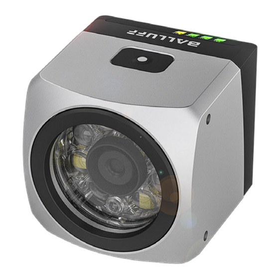
- Page 72 Name des Herstellers vendorUrl URL zur Website des Herstellers Beispiel: "firmwareRevision": "1.0.3", "hardwareRevision": "20", "nameOfStation": "B00000000000045", "productId": "BVS ID-M1280BF1-L3-000", "productInstanceUri": "https://products.balluff.com/BVS%20ID-M1280BF1-L3-000/ BVS0060", "productName": "BVS ID-M1280BF1-L3-000", "productText": "1D/2D code sensor, autofocus, w/r light, IO-Link", "serialNumber": "D800000000000045", "vendorName": "Balluff", "vendorUrl": "https://www.balluff.com" deutsch...
- Page 73 BVS ID-M1280xF1-xx-xxx Open Source Lizenzen verwendeter Programmbibliotheken abfragen Ressource: licenses URL: http://HOSTNAME/api/balluff/v1/licenses Antwort: Als Antwort werden Textdaten im Markdown-Format mit MIME-Typ text/plain generiert, auf der alle verwendeten Programmbibliotheken und deren Lizenzen gelistet sind. Handbuch abfragen Ressource: documents URL: http://HOSTNAME/api/balluff/v1/documents Antwort:...
- Page 74 BVS ID-M1280xF1-xx-xxx Diagnosewerte abfragen Ressource: diagnostics URL: http://HOSTNAME/api/balluff/v1/diagnostics Antwort: Objekt Inhalt internalTemperature Interne Temperatur Signalqualität des eingelesenen Codes. Ein Wert von 255 bedeutet, dass keine Signalqualität berechnet signalQuality wurde. Unterteilt in zwei Unterobjekte: • totalOperatingHours: Gesamtbetriebsstundenzähler für die Betriebsstunden seit Auslieferung des operatingHours Geräts...
- Page 75 "NORMAL_0" HINWEIS Diagnose-Werte können auch einzeln abgefragt werden, indem dem Befehl diagnostics angehängt wird (z.B. http://HOSTNAME/api/balluff/v1/diagnostics/vibration). Die Sub-Objekte "operatingHours" und "operatingHoursSinceBoot" können nicht einzeln abgefragt werden. Stattdessen können sie gemeinsam durch die Abfrage des Elternobjekts "operatingHours" via http://HOSTNAME/api/balluff/v1/ diagnostics/operatingHours geholt werden.
- Page 76 BVS ID-M1280xF1-xx-xxx Gerätestatus abfragen (Health State) Ressource: diagnostics/health URL: http://HOSTNAME/api/balluff/v1/diagnostics/health Der Health State repräsentiert den Gerätestatus des BVS ID gemäß NAMUR Recommendation NE107. Clients können diese Variable auswerten, um den Gerätezustand zu bestimmen. Antwort: Objekt Inhalt Gerätestatus. Mögliche Werte sind •...
- Page 77 BVS ID-M1280xF1-xx-xxx Datum/Uhrzeit abfragen Ressource: time URL: http://HOSTNAME/api/balluff/v1/time Antwort: Objekt Inhalt time Datum und Uhrzeit im Format "YYYY-MM-DDTHH:MM:SS.000+00:00Z" Beispiel: "time": "2024-09-01T07:20:06.000+00:00Z" HINWEIS Die vier Zahlen zwischen "+" und "Z", getrennt durch einen Doppelpunkt, geben die Zeitverschiebung im Bezug zur UTC0-Zeitzone an und entsprechen somit der Zeitzone der SensorApp.
- Page 78 BVS ID-M1280xF1-xx-xxx Ergebnisse abfragen Ressource: vision/inspection/results URL: http://HOSTNAME/api/balluff/v1/vision/inspection/results Antwort (in Abhängigkeit zu aktivierten Ergebnisdaten): Objekt Inhalt ID des aktiven Inspektionsprogramms inspectionResult Inspektionsergebnis resultMessage Ergebnisnachricht type Code-Typen text Gelesene Texte expectedValue Erwartete Texte qualityMin Minimale Code-Qualitäten qualityFull Qualitätsstrings bestehend aus einer Reihe von Qualitätsmerkmalen moduleSize Modulgrößen der Codes...
- Page 79 BVS ID-M1280xF1-xx-xxx Beispiel: "id": 1, "inspectionResult": true, "resultMessage": "", "type": { "Code 1": "QR Code" "text": { "Code 1": "Matrix" "expectedValue": { "Code 1": "*" "qualityMin": { "Code 1": "B" "qualityFull": { "Code 1": "AAABABBA" "moduleSize": { "Code 1": 20.83460968299469 "centerX": { "Code 1":...
- Page 80 BVS ID-M1280xF1-xx-xxx Ergebnisse als Binärstring abfragen Ressource: vision/inspection/resultsAsBinaryString URL: http://HOSTNAME/api/balluff/v1/vision/inspection/resultsAsBinaryString Antwort: Objekt Inhalt binaryData Ergebnisdaten in Bytes, repräsentiert als HEX-Werte Beispiel: "binaryData": "00 00 FF 00 00 00 00 00 00 00 00 00 00 00 00 00 00 00 00 00 00 00 00 51 52 20 43 6F 64 65 00 00 00 00 00 00 00 00 00 00 00 00 00 42 61 6C 6C 75 66 66 00 00 00 00 00 00 00 00 00 00 00 00 00 AF 56 4D 92 00 64 24 40"...
- Page 81 BVS ID-M1280xF1-xx-xxx "ready": false, "reportError": false, "resultDataError": false, "simulationMode": true, "systemError": false, "triggerOverflow": false, "waitingForTrigger": false HINWEIS Status-Werte können auch einzeln abgefragt werden, indem dem Befehl vision/status angehängt wird (z.B. http://HOSTNAME/api/balluff/v1/vision/status/ready). deutsch ...
- Page 82 Systemsettings ausgewählt werden. Bei eingeschalteter Benutzerverwaltung muss der Bearer, der durch einen Login-Aufruf zurückgeliefert wird, im Header jedes POST-Befehls mittels "Authorization: Bearer 23d6c502-6e5d-433f-8213-35bab1a37c39" angegeben werden. Datum/Uhrzeit setzen Ressource: time URL: http://HOSTNAME/api/balluff/v1/time Anfrage: Objekt Inhalt time Datum und Uhrzeit im Format "YYYY-MM-DDTHH:MM:SS.000Z" Beispiel: "time":...
- Page 83 Resource: vision/inspection/inputs URL: http://HOSTNAME/api/balluff/v1/vision/inspection/inputs Anfrage: Objekt Inhalt referenceValue UTF-8-codierter Referenzwert Beispiel: "referenceValue": "Balluff" Inspektion triggern Resource: vision/inspection/trigger URL: http://HOSTNAME/api/balluff/v1/vision/inspection/trigger LED aufleuchten lassen Ressource: moduleblink URL: http://HOSTNAME/api/balluff/v1/http://HOSTNAME/api/balluff/v1/moduleblink Die obere LED des BVS ID leuchtet nach der POST-Anfrage für ca. 1 Minute.
- Page 84 BVS ID-M1280xF1-xx-xxx Benutzer anmelden Resource: users/login URL: http://HOSTNAME/api/balluff/v1/vision/users/login Der "expert" - Benutzer ist der einzige gültige REST-Benutzer mit dem in der SensorApp vergebenen Passwort. Anfrage: Objekt Inhalt username UTF-8-kodierter Benutzername password UTF-8-kodiertes Passwort Beispiel: "username":"expert", "password":"0123456789012" Antwort: Objekt Inhalt Bearer String mit dem Session-Token ...
- Page 85 Logout mit Sessiontoken (Bearer) bei aktivierter Benutzerverwaltung Das Session-Token muss im HTTP-"Authorization"-Header per "Authorization: Bearer 23d6c502-6e5d-433f-8213-35bab1a37c39" mitgegeben werden. Beispiel: curl -X 'POST' \ 'http://192.168.10.2/api/balluff/v1/users/logout' \ -H 'accept: */*' \ -H 'Authorization: Bearer 0294a194-970f-43e8-8d3d-dec8e8e65a10' \ -d '' Logout mit user/password bei deaktivierter Benutzerverwaltung...
- Page 86 BVS ID-M1280xF1-xx-xxx IO-Link / Feldbus Prozessdatenprotokoll 4.3.1 Einleitung IO-Link integriert konventionelle und intelligente Aktoren und Sensoren in Automatisierungssysteme, wobei der gemischte Betrieb ohne Mehraufwand möglich ist. IO-Link ist als Kommunikationsstandard unterhalb der klassischen Feldbusse vorgesehen. Als feldbusunabhängige Übertragung nutzt IO-Link bereits vorhandene Kommunikationssysteme (Feldbusse oder Ethernet-basierte Systeme).
- Page 87 BVS ID-M1280xF1-xx-xxx 4.3.2 Funktionsbausteine Zur Vereinfachung der Kommunikation, stellt die Balluff GmbH für die gängigsten Steuerungen entsprechende Funktionsbausteine zur Verfügung. Diese können von der Balluff Website (www.balluff.com) im Downloadbereich des Produkts heruntergeladen werden. Diese Funktionsbausteine übernehmen alle Protokoll-, eventuelle Toggle- und Sicherheitsaufgaben automatisch.
- Page 88 BVS ID-M1280xF1-xx-xxx 4.3.3 Prozessdaten Der Datenaustausch erfolgt über die Prozessdaten, die je nach verwendetem Steuerungssystem im Eingangs- und Ausgangspuffer, oder in einem Speicherfeld abgebildet werden. Es werden 32 Byte Eingangsdaten und 32 Byte Ausgangsdaten inklusive Bitleisten genutzt. Die Belegung ist nachfolgend beschrieben. Dabei entspricht die Subadresse 0x00 jeweils der Anfangsadresse im entsprechenden Datenfeld.
- Page 89 BVS ID-M1280xF1-xx-xxx 4.3.3.1 Eingangspuffer Byteadresse Result Data Waiting for Ready Status Byte Available Trigger n+1 Result Data Trigger System Error - Input Data Error - Report Error Error Byte Error Overflow Job Error Job End Job Start 1. Bitleiste Statusbyte (erster Toggle Zyklus) / Daten Datenlänge Byte 0 (erster Toggle Zyklus) / Daten Datenlänge Byte 1 (erster Toggle Zyklus) / Daten Daten...
- Page 90 BVS ID-M1280xF1-xx-xxx Beschreibung der Einzelsignale Bitleiste Bit Nummer Name Funktionsbeschreibung Nicht verwendet Job Start Neuer Übertragungs-"Job" wird gestartet. 0: Kein Job vorhanden. Job End 1: Der Job wurde ohne Fehler beendet. 0: Job wurde ohne Fehler beendet. Job Error 1: Job fehlerhaft bearbeitet oder abgebrochen. Nicht verwendet Ein Zustandswechsel während eines Jobs zeigt an, dass der BVS ID bereit ist, weitere Daten zu übermitteln.
- Page 91 BVS ID-M1280xF1-xx-xxx Error Byte Bit Nummer Name Funktionsbeschreibung Ein Trigger-Signal konnte vom BVS ID nicht akzeptiert werden. Trigger Overflow Ein neues Ergebnis steht zur Verfügung, obwohl das alte nicht vollständig von der SPS abgeholt Result Data Error wurde. Die alten Daten wurden überschrieben. Die Reportdatei wurde nicht übertragen.
- Page 92 BVS ID-M1280xF1-xx-xxx 4.3.3.2 Ausgangspuffer Byteadresse Reset Error Trigger 1. Bitleiste n+1 Befehlserkennung Status Byte Datenlänge Byte 0 oder Daten Error Byte Datenlänge Byte 1 oder Daten Daten Daten Daten Daten Daten Daten Daten n+31 Reset Error Trigger 2. Bitleiste Dieser Ausgangspuffer wird der SPS befüllt und vom BVS ID gelesen. Beschreibung der Einzelsignale Bitleiste Bit Nummer...
- Page 93 BVS ID-M1280xF1-xx-xxx 4.3.4 Protokollablauf Wird die Kommunikation vom IO-Link-Master angestoßen (wir sprechen von Job), dann beginnt die Übertragung der jeweils aktuellen Prozessdaten. Über die Signale in der 1. Bitleiste des Ausgangspuffers besteht die Möglichkeit, das Gerät von der SPS zu steuern. •...
- Page 94 BVS ID-M1280xF1-xx-xxx Über das Job End-Bit erkennt die SPS, dass eine Antwort gesendet wurde und die Daten gültig sind. • SPS löscht das Job-Bit. • BVS ID löscht das Job End-Bit und Job Start-Bit zurück. Über die SPS kann der BVS ID über Signale der Bitleiste in jedem Steuerungszyklus gesteuert werden wenn die entsprechenden Bedingungen (z.B.: Ready, Waiting for Trigger, ..
- Page 95 BVS ID-M1280xF1-xx-xxx 4.3.4.1 Toggle-Mechanismus Für den Fall, dass mit einem Befehl oder mit einer Antwort mehr Daten übertragen werden sollen, als im Eingangs- / Ausgangspuffer zur Verfügung steht, kommt ein Toggle-Mechanismus zum Einsatz. D.h., dass in weiteren SPS-Zyklen weitere Daten sequentiell übertragen werden. Dies betrifft nur die Befehle •...
- Page 96 BVS ID-M1280xF1-xx-xxx Ablaufdiagramm Handshake mit Input Toggle deutsch...
- Page 97 BVS ID-M1280xF1-xx-xxx 4.3.5 Befehle Der BVS ID kann im Status „Ready“ (Ready – Signal „1“) über Befehle gesteuert werden. In diesem Zustand kann die SPS-Befehle zum BVS ID senden und erhält danach eine Antwort, die eine Bestätigung auf den Befehl enthält (CMD Status) und die entsprechenden Daten. Befehl Befehlscode Funktionsbeschreibung...
- Page 98 BVS ID-M1280xF1-xx-xxx 4.3.5.1 Set Inspection ID Mit diesem Befehl wird das aktive Inspektionsprogramm im BVS ID umgeschaltet. Die Inspektionsprogrammnummer (ID) wird in der SensorApp festgelegt. Befehl: Subadresse Daten Bedeutung n+00 0x02 1. Bitleiste (Job Start) n+01 0x01 Inspektions-ID setzen n+02 0x04 Nutzdatenlänge Byte 0 n+03...
- Page 99 BVS ID-M1280xF1-xx-xxx 4.3.5.2 Get Inspection ID Mit diesem Befehl wird die aktuelle Inspektionsprogrammnummer vom BVS ID abgefragt. Befehl: Subadresse Daten Bedeutung n+00 0x02 1. Bitleiste (Job Start) n+01 0x02 Inspektions-ID abfragen n+02 n+03 … n+31 0x02 2. Bitleiste Antwort: Subadresse Daten Bedeutung n+00...
- Page 100 BVS ID-M1280xF1-xx-xxx 4.3.5.3 Get Results Nach einem Inspektionsdurchlauf signalisiert der BVS ID über das Result Data Available-Bit dass Ergebnisdaten zum Abholen bereit sind. Mit diesem Befehl wird ein Ergebnispaket mit der in der SensorApp definierten Größe vom BVS ID abgeholt. Je nach Größe des definierten Datenpakets kann ein Toggeln notwendig werden, d.h. es werden nacheinander mehrere Datenblöcke übermittelt.
- Page 101 BVS ID-M1280xF1-xx-xxx 4.3.5.4 Set Inputs Über die Steuerung können Referenzwerte an den BVS ID geschickt werden, zu denen die gefunden Codes verglichen werden. Das Format dieser Referenzwerte wird in der SensorApp definiert. Je nach Größe des definierten Datenpakets kann ein Toggeln notwendig werden, d.h. es werden nacheinander mehrere Datenblöcke übermittelt.
- Page 102 BVS ID-M1280xF1-xx-xxx 4.3.5.5 Get Date Time Im BVS ID kann die Systemzeit und -datum eingestellt oder automatisch bestimmt werden. Dieser Befehl erfragt diese Systemzeit vom BVS ID. Befehl: Subadresse Daten Bedeutung n+00 0x02 1. Bitleiste (Job Start) n+01 0x06 Datum / Zeit abfragen n+02 n+03 …...
- Page 103 BVS ID-M1280xF1-xx-xxx 4.3.5.6 Set Date Time Mit diesem Befehl kann die BVS ID Systemzeit und -datum von der SPS gesetzt werden. Da der BVS ID keine Batterie besitzt verliert der Sensor diese Information beim Ausschalten. Befehl: Subadresse Daten Bedeutung n+00 0x02 1.
- Page 104 BVS ID-M1280xF1-xx-xxx Übersicht IO-Link-Daten und -Funktionen 4.4.1 Übersicht der enthaltenen Funktionen 4.4.1.1 Primäre Funktionen • Identifikation (Identification) • Geräteerkennung (Device Discovery) • Netzwerkeinstellungen (Network Settings) • Prozessdaten (Process Data) • Signalqualität (Signal Quality) 4.4.1.2 Sekundäre Funktionen • Grundlegende Statistik (Basic Statistics) •...
- Page 105 BVS ID-M1280xF1-xx-xxx 4.4.2 Gerätevarianten Es sind folgende zwei Varianten verfügbar, die sich in ihren Prozessdatenprofilen unterscheiden: • Default • Comprehensive Condition Monitoring Die Funktionen bleiben dabei unverändert. In den Prozessdaten wird ein Protokoll übertragen. Anzahl Anzahl IO-Link- Minimale Variante Device ID Baudrate PDInput PDOutput...
- Page 106 4.4.4 ISDU – Identifikationsdaten Data Name Index Subindex Zugriff Länge Datentyp Default Storage Identifikation 0x0010 Vendor Name 7 Byte STRING “Balluff” (16) 0x0011 Vendor Text 15 Byte STRING "www.balluff.com” (17) 0x0012 z. B. "BVS ID- Product Name [...] STRING (18) M1280BF1-L3-000"...
- Page 107 BVS ID-M1280xF1-xx-xxx Data Name Index Subindex Zugriff Länge Datentyp Default Storage Signalqualität Signal Quality 2 Byte 0x00CF Current Signal Quality 1 Byte UINT8 (207) Signal Quality Bad 1 Bit BOOL Data Name Index Subindex Zugriff Länge Datentyp Default Storage Grundlegende Statistik Statistics 8 Byte Data Configuration...
- Page 108 BVS ID-M1280xF1-xx-xxx Data Name Index Subindex Zugriff Länge Datentyp Default Storage Spannungs- und Stromüberwachung Voltage Monitoring 0x2200 2 Byte UINT16 Detection Time Duration (8704) Data Name Index Subindex Zugriff Länge Datentyp Default Storage Status extremer Umweltbedingung Lifetime Extreme 8 Byte Thresholds Threshold Vibration 4 Byte...
- Page 109 BVS ID-M1280xF1-xx-xxx Data Name Index Subindex Zugriff Länge Datentyp Default Storage Neigungsdetektion und Einstellhilfe Inclination Alarm Status 2 Byte Inclination Alarm 0x2152 1 Byte BOOL Teaching Status (8530) Inclination Alarm Status 1 Byte BOOL Reference Taught 12 Byte Position X Reference Value 4 Byte FLOAT32 0x2153 ...
- Page 110 BVS ID-M1280xF1-xx-xxx Data Name Index Subindex Zugriff Länge Datentyp Default Storage Diagnoseunterdrückung Diagnosis Level 0x0070 1 Byte UINT8(ENUM) Configuration (112) Event Code Suppression 10 Byte 0x0071 (113) Event Code Suppression 1...5 2 Byte UINT16 Nein Event Code Suppression 0x0072 2 Byte UINT16 Teach-in (114)
- Page 111 BVS ID-M1280xF1-xx-xxx 4.4.5 System Commands Command-Wert Geräteaktion Device Reset – Device Reset bedeutet einen Warmstart des BVS ID. Dabei wird der 0x80 (128) Microcontroller neu hochgefahren und alle Initialisierungen neu durchgeführt, ohne dass eine Änderung der Parameterwerte erfolgt. 0x81 (129) Application Reset 0x82 (130) ...
- Page 112 BVS ID-M1280xF1-xx-xxx 4.4.6 Events Event-Code Event-Typ Event-Beschreibung-Abhilfe Device Status Process Data Profilauswahl nicht 0x1850 (6224) Benachrichtigung anwendbar – Standardwert wird 0 – Device is operating properly. verwendet Process Data Update Timeout – dient 0x1851 (6225) Benachrichtigung 0 – Device is operating properly. nur zur Information Mehrfache Process Data Update 0x1852 (6226)
- Page 113 BVS ID-M1280xF1-xx-xxx Event-Code Event-Typ Event-Beschreibung-Abhilfe Device Status Falsche Last/Kabelbruch, analoger Stromausgang Pin 2 0x8D0D (36109) Warnung 2 – Out-of-Specification → Verkabelung bzw. angeschlossene Geräte prüfen. Die Zeit ist abgelaufen. Dieses Event meldet die Zeitüberschreitung der Minimalwert-/Maximalwert-/ Durchschnitt-Berechnung. Es meldet keine Zeitüberschreitung für 0x8D0E (36110) Benachrichtigung 0 –...
- Page 114 BVS ID-M1280xF1-xx-xxx 4.4.7 Kommunikationsparameter Die grundlegende IO-Link-Spezifikation für BVS ID-M1280BF1-L3-000 lautet wie folgt: Spezifikation IO-Link-Bezeichnung Wert Übertragungsrate COM COM3 (230,4 kBaud) Minimale Zykluszeit Device min cycle time 0x27 (3,9 ms) Frame-Spezifikation: M-Sequence Capability: 0x1B – Anzahl Bedarfsdaten Preoperate – M-Sequence Type Preoperate 2 Byte –...
- Page 115 Die Identifikationsdaten dienen zur Identifikation und Verwaltung der IO-Link-Devices. ISDU Subinde Zugrif Data Name Index Länge Datentyp Default Storage 0x0010 Vendor Name 7 Byte STRING “Balluff” (16) 0x0011 Vendor Text 15 Byte STRING "www.balluff.com” (17) 0x0012 Product Name [...] STRING z. B. "BVS ID-M1280BF1-L3-000" (18)
- Page 116 Mit dem Parameter Location Tag kann ein String (maximal 32 Byte) in das Device geschrieben werden. Typischerweise beschreibt dieser Wert den Ort des Produkts im Einsatzbereich. Product Type Code Der Balluff Typenschlüssel ist fest im BVS ID hinterlegt. Product Order Code Der Balluff Bestellcode ist fest im BVS ID hinterlegt.
- Page 117 BVS ID-M1280xF1-xx-xxx 4.4.8.3 Netzwerkeinstellungen (Network Settings) Beschreibung Mit den Netzwerkeinstellungen kann die IP-Konfiguration gesetzt und gelesen werden. ISDU Subinde Zugrif Data Name Index Länge Datentyp Default Storage Network Settings 46 Byte Nein ≤ 15 IP Address STRING Nein Byte 0x00B ≤...
- Page 118 BVS ID-M1280xF1-xx-xxx 4.4.8.5 Signalqualität (Signal Quality) Beschreibung Die Signalqualität wird in Prozentschritten als Wert zwischen 0 und 100 % angegeben. Wenn die Signalqualität nicht bereitgestellt werden kann, wird ein Ersatzwert von 0xFF (255) ausgegeben. Der Schwellenwert für die Überwachungsfunktion kann eingestellt werden und dient zur Definition von zwei Zuständen der Signalqualität. Gleich oder oberhalb des Schwellenwerts gilt die Signalqualität als gut, unterhalb des Schwellenwerts gilt die Signalqualität als schlecht.
- Page 119 BVS ID-M1280xF1-xx-xxx Abbildung der Gesamtcodequalität auf die Signalqualität Die Einzelcodequalitäten A, B, C, D, E, F werden wie folgt auf ganzzahlige Signalqualitätswerte abgebildet: Codequalitätswert Signalqualitätswert 100% Prozessdaten ID Name Beschreibung Richtung 0x0020 (32) Current Signal Quality Ausgabe der aktuellen Signalqualität in Prozentschritten von 0 % bis 100 %. Eingang Ausgabe der aktuellen Signalqualitätsevaluation, TRUE bedeutet eine 0x0021 (33)
- Page 120 BVS ID-M1280xF1-xx-xxx System Commands Command-Wert Geräteaktion Application Reset – Setzt den Schwellenwert mit ISDU Index 0xCE Low Signal Quality Threshold auf 0x81 (129) Default 0 zurück. Dadurch ist das Feature deaktiviert und die Evaluation auf dem Index 0xCF Subindex 2 ergibt immer FALSE. Reset Factory Settings –...
- Page 121 BVS ID-M1280xF1-xx-xxx 4.4.9 Sekundäre Gerätefunktionen 4.4.9.1 Grundlegende Statistik (Basic Statistics) Beschreibung Mit der Funktion Basic Statistics können Statistikvorgänge ausgeführt werden, wie z. B. die Berechnung von Minimum, Maximum und Durchschnitt. Darüber hinaus ist es möglich, den gleitenden Durchschnitt zu berechnen. Mit Basic Statistics können Trends für die gewählte Eingabe über die angegebene Dauer (zwischen 1 Sekunde und 1 Woche oder 1 bis 1000 Abtastpunkte) anzeigt werden.
- Page 122 BVS ID-M1280xF1-xx-xxx Das nächste Bild zeigt den gleitenden Durchschnitt unter Verwendung der Methode des periodischen Fensters. Process Data Object ID Name Beschreibung Richtung 0x0053 (83) Minimum Minimalwert Eingang 0x0054 (84) Maximum Maximalwert Eingang 0x0055 (85) Average Durchschnitt Eingang 0x0056 (86) Moving Average ...
- Page 123 BVS ID-M1280xF1-xx-xxx ISDU HINWEIS Minimum, Maximum, Average and Moving Average outputs werden im FLOAT32-Format ausgegeben. Bevor sie weiterverarbeitet werden und von FLOAT32 zu INT32 oder UINT32 konvertiert werden, muss das Ausgangssignal geprüft werden, ob es größer als INT32_Max oder UINT32_Max ist. Wenn es größer ist, sollte der Datentyp UINT64 oder INT64 verwendet werden.
- Page 124 BVS ID-M1280xF1-xx-xxx Statistics Data Configuration: Time Period Value Time Period Value kann von 1 Sekunde bis 1 Woche oder 1 bis 1000 Messwerte eingestellt werden. Über welchen Durchschnitt Minimum, Maximum und Durchschnitt berechnet werden sollen. Weitere Überprüfungen werden intern durchgeführt, und bei unangemessener Auswahl des Time Period Value wird ein Standardfehler zurückgegeben.
- Page 125 BVS ID-M1280xF1-xx-xxx Statistics Data Configuration: Number of Samples Gesamtzahl der während des Start- und Stoppbetriebs der Minimalwert/Maximalwert/Durchschnitt-Funktion gelesenen Messwerte. Statistics Data Output: Status Bitposition Bedeutung Beschreibung Configured 1 – alle Eingänge sind konfiguriert Started Min/Max/Avg 1 – Min/Max/Avg läuft Started Moving Average 1 –...
- Page 126 BVS ID-M1280xF1-xx-xxx 4.4.9.2 Betriebsstundenzähler (Operating Hours Counter) Beschreibung Der Betriebsstundenzähler kann die Betriebsstunden eines Device sekundengenau erfassen. Es gibt insgesamt drei Betriebsstundenzähler. Neben einem Betriebsstundenzähler für die Betriebsstunden seit Start des Device gibt es einen Gesamtbetriebsstundenzähler und einen kundenspezifischen Betriebsstundenzähler, der zurücksetzbar ist.
- Page 127 BVS ID-M1280xF1-xx-xxx Operating Hours Saving Mode Es kann das aktuelle Speicherverhalten eingestellt werden. Wert Bedeutung Beschreibung Die erste Speicherung wird 1 Minute nach dem Einschalten durchgeführt, danach verdoppelt sich das 0x00 (0) Dynamic Speicherintervall nach jedem Speichervorgang. Dies ist auf ein Speicherintervall von 12 Minuten begrenzt.
- Page 128 BVS ID-M1280xF1-xx-xxx System Commands Command-Wert Geräteaktion Application Reset – Setzt den Custom Boot Cycle Counter mit ISDU-Index 0x58 ubindex 2 auf den 0x81 (129) Defaultwert 0 zurück. Reset Factory Settings – Setzt den Custom Boot Cycle Counter mit ISDU-Index 0x58 Subindex 2 auf den 0x82 (130) Defaultwert 0 zurück.
- Page 129 BVS ID-M1280xF1-xx-xxx System Commands Command-Wert Geräteaktion Application Reset – Setzt die Voltage Monitoring Detection Time Duration mit ISDU-Index 0x2200 auf den 0x81 (129) Defaultwert 10 zurück. Reset Factory Settings – Setzt die Voltage Monitoring Detection Time Duration mit ISDU-Index 0x2200 auf 0x82 (130) den Defaultwert 10 zurück.
- Page 130 BVS ID-M1280xF1-xx-xxx ISDU Subinde Zugrif Data Name Index Länge Datentyp Default Storage Lifetime Extreme 8 Byte Thresholds Threshold Vibration 4 Byte FLOAT32 Nein 100.0 0x00D 0 Upper Threshold (208) 2 Byte INT16 Nein Temperature Lower Threshold 2 Byte INT16 Nein Temperature ...
- Page 131 BVS ID-M1280xF1-xx-xxx Events Event- Event-Typ Event-Beschreibung-Abhilfe Device-Status Code 0x8D13 Warnung Eine oder mehrere Extrembedingungen liegen vor. 0 – Device is operating properly. (36115) Variantenabhängigkeit Die Funktionalität ist in allen Varianten verfügbar. deutsch ...
- Page 132 BVS ID-M1280xF1-xx-xxx 4.4.9.6 Interne Temperatur (Internal Temperature) Beschreibung Der BVS ID verfügt über eine interne Temperaturüberwachung. Dabei wird die Gerätetemperatur erfasst sowie Maximal- und Minimalwerte seit Produktion und seit letztem Neustart des BVS ID. Für das Modul Gerätetemperatur kann ein oberer und ein unterer Schwellenwert festgelegt werden. Der BVS ID löst bei einer Schwellenwertüberschreitung sowie beim Überschreiten bzw.
- Page 133 BVS ID-M1280xF1-xx-xxx Device Temperature Alarm Configuration Einstellung für den unteren Schwellenwert (in °C) für die Gerätetemperaturwarnung (0x8D20) und oberen Schwellenwert (in °C) für die Gerätetemperaturwarnung (0x8D10). Events Event- Event-Typ Event-Beschreibung-Abhilfe Device-Status Code Temperature Fault – Overload – Der BVS ID wird außerhalb der 0x4000 Fehler gerätespezifischen Temperaturgrenzen betrieben.
- Page 134 BVS ID-M1280xF1-xx-xxx 4.4.9.7 Neigungsdetektion und Einstellhilfe (Inclination and Installation Aid) Beschreibung Dieses Feature bietet zwei Funktionen: • Neigungserkennung • Montage- und Ausrichthilfe Die Neigungsdetektion erkennt eine Neigungsabweichung im Vergleich zu einer Referenzposition. Die Referenzposition kann frei gewählt und eingelernt werden. Der interne Lagesensor orientiert sich dabei an der vertikalen Erdachse.
- Page 135 BVS ID-M1280xF1-xx-xxx Erkennbare und nichterkennbare Verstellungen: Die Verstellung kann Rotation, Neigung oder Bewegung sein. Mit der Funktion kann die Neigung (grüner Pfeil) erkannt werden, Verschiebungen oder Rotation (rote Pfeile) nicht. Mathematik/Algorithmus Die Neigungsabweichung wird weder mit der horizontalen Ebene noch mit dem vertikalen Gravitationsfeld verglichen, sondern mit der vom Endbenutzer eingelernten Orientierung.
- Page 136 BVS ID-M1280xF1-xx-xxx Alarm Threshold Schwellenwert der Neigungsabweichung für die Auslösung eines Events. HINWEIS Hysterese berücksichtigt, Wert ist auf 0° (nach oben) und −1° (nach unten) festgelegt. • Werte: 1…180 • Einheit: Grad (°) • Default_Wert: 10° Alarm Teaching Status Beschreibung Device ist noch nicht eingelernt, keine Referenzorientierung eingestellt, Neigungswert nicht verfügbar.
- Page 137 BVS ID-M1280xF1-xx-xxx System Commands System Commands zum Einlernen (Teach-in) und Festlegen der Referenzorientierung. HINWEIS Das Device kann die Neigung erst berechnen, wenn die Referenzposition eingelernt ist. Command-Wert Geräteaktion Set Reference Orientation – Referenzorientierung der Ist-Position des BVS ID einstellen. 0xC0 (192) Antworten: ACK: Befehl erfolgreich, Referenz gespeichert.
- Page 138 BVS ID-M1280xF1-xx-xxx 4.4.9.8 Vibrationsdetektion (Vibration) Beschreibung Der BVS ID stellt zwei Schwingungswerte zur Verfügung, die wertvolle Informationen zur vorbeugenden Wartung liefern: • Gesamtgeschwindigkeit in [mm/s], die den allgemeinen Maschinenzustand angibt (unterer Frequenzbereich) • Gesamtbeschleunigung in [g], die den Lagerzustand anzeigt (höherer Frequenzbereich) Diese sekundäre Gerätefunktion ermöglicht die Messung der Schwinggeschwindigkeit als physikalische Umgebungseigenschaft eines mechanischen Systems.
- Page 139 Vibrationsquelle gemessen, sondern die Vibrationen des gesamten mechanischen Systems. Diese Funktion ist dem ISO-10816-3-Standard angelehnt, aber für eine detaillierte Schwingungsdiagnose bietet Balluff spezielle Sensoren an. Die Produktfamilie ist so konzipiert, dass sie eine vollständige Überwachungsfunktionalität bietet, wobei die Zustandsüberwachung die primäre Funktion des Sensors ist und dieser am Objekt oder an der Maschine montiert wird.
- Page 140 BVS ID-M1280xF1-xx-xxx ISDU Subinde Zugrif Data Name Index Länge Datentyp Default Storage 0x210E Vibration Level 4 Byte FLOAT32 (8462) Vibration Alarm 5 Byte Configuration 0x210F Vibration Alarm Enable 1 Byte BOOL Nein (8463) Vibration Alarm 4 Byte FLOAT32 Nein Threshold 0x2110 Vibration Alarm Status...
- Page 141 BVS ID-M1280xF1-xx-xxx 4.4.9.9 Feuchtigkeitsdetektion (Humidity) Beschreibung Die Funktion überwacht die Luftfeuchtigkeit im BVS ID und informiert über Änderungen durch entsprechende IO-Link- Events. Die Feuchtigkeitserkennung liefert eine sofortige Reaktion im Falle eines kritischen Ausfalls. Diese Reaktion wird ausgelöst, wenn die Feuchte über einen festen Schwellenwert ansteigt, und gibt Entwarnung, wenn ein zufriedenstellendes Feuchteniveau wieder erreicht wird.
- Page 142 BVS ID-M1280xF1-xx-xxx 4.4.9.10 Speichernutzungsüberwachung (Storage Usage Monitoring) Beschreibung Alle veränderlichen Daten werden in einem permanenten Speicher auf dem BVS ID gespeichert. Die Daten werden in verschiedenen Abschnitten für unterschiedliche Zugriffsund Verwendungszwecke gespeichert. Da die Anzahl an Schreibzyklen im Permanentspeicher begrenzt ist, wird die Anzahl in jedem Abschnitt mit einem Zähler überwacht.
- Page 143 Failure vorgesehene Funktion auszuführen. Eine Neukonfiguration (Zurücksetzen auf Werkseinstellungen) kann weiterhelfen. Sonst muss der Balluff-Service kontaktiert oder der BVS ID ausgetauscht werden. Detailed Device Status Detailed Device Status zeigt die aktuell anstehenden Diagnosemeldungen (Fehler, Warnung) an. Für eine Event- Übersicht siehe Kapitel "Events".
- Page 144 BVS ID-M1280xF1-xx-xxx 4.4.9.12 Diagnoseunterdrückung (Diagnosis Suppression) Beschreibung Die Diagnoseunterdrückung dient dazu, Diagnosemeldungen des BVS ID zu unterdrücken. Hierfür gibt es 2 Möglichkeiten: • Diagnoseunterdrückungslevel, das ein generelles Unterdrücken von Meldungen eines bestimmten Niveaus (Benachrichtigung, Warnung, Fehler) zulässt. • Event-Code-Unterdrückung von bis zu 5 Events als Liste oder über ein Teach-in. ISDU Subinde Zugrif...
- Page 145 BVS ID-M1280xF1-xx-xxx 4.4.9.13 Resetbefehle (Reset Commands) Beschreibung Der BVS ID unterstützt verschiedene Reset Commands zum Zurücksetzen der eingestellten Parameter auf Defaultwerte. Auf diese Kommandos wird jeweils über System Commands zugegriffen. Diese Funktion ist in der IO-Link-Spezifikation definiert und nach der Version 1.1.2 umgesetzt. ISDU Subinde Zugrif...
- Page 146 BVS ID-M1280xF1-xx-xxx 4.4.9.14 Variantenkonfiguration (Variant Configuration) HINWEIS Nach einer Variantenumstellung kann es zu einer inkonsistenten Konfiguration kommen, da es keine automatische Umstellung von Parametern gibt. Daher wird die Einrichtung in folgender Reihenfolge empfohlen: Varianteneinstellung Reset durchführen oder gültige Parameter einstellen. ISDU Subinde Zugrif...
- Page 147 4.4.9.15 Bedeutung der LED-Zustände und Konfiguration (LED Meaning and Configuration) Beschreibung Es wird immer nur das Signal mit der höchsten Priorität angezeigt. Die Signale werden mit absteigender Priorität aufgelistet. Balluff Standard (LED 1 - IO-Link) Name Signal Bedeutung Das Device Discovery kann über ein System...
- Page 148 LED Standard Selection Es kann mit Hilfe eines Parameters zwischen zwei verschiedenen Signalisierungsstandards gewählt werden. Der Parameter definiert, welcher Signalisierungsstandard verwendet werden soll: Wert Standard BALLUFF NAMUR Der Parameter wird durch die Application Reset und Factory Reset zurückgesetzt. deutsch...
- Page 149 BVS ID-M1280xF1-xx-xxx 4.4.9.16 Prozessdateninformation und -konfiguration (Process Data Info and Configuration) Beschreibung Prozessdateninformation und -Konfiguration bietet verschiedene Möglichkeiten rund um Prozessdaten: • Auswahl eines der vom BVS ID vorgegebenen Prozessdatensets • Information über den Aufbau der Ein- und Ausgangsdaten • Information über den letzen gültigen Wert für Ein- bzw.
- Page 150 BVS ID-M1280xF1-xx-xxx Events Bei speziellen Prozessdatenwerten überprüft der BVS ID selbstständig, ob die Werte im vom BVS ID vorgegebenen Zeitraum aktualisiert werden. Wird dadurch ein Update-Timeout ausgelöst, wird dies über folgende Diagnosemeldungen ausgegeben: Event- Event-Typ Event-Beschreibung-Abhilfe Device-Status Code 0x1851 Benachrichtigung Process Data Update Timeout –...
- Page 151 BVS ID-M1280xF1-xx-xxx 4.4.9.17 Profilcharakteristik (Profile Characteristic) Beschreibung Profile Characteristic ist ein lesbarer Parameter, der Auskunft darüber gibt, welche IO-Link-Profile unterstützt werden. Er wird hauptsächlich dazu genutzt, dass Profil-Funktionsbausteine der Steuerungseinheit erkennen können, welche Profile bzw. Funktionen auf dem BVS ID verfügbar sind. Dieser Parameter ist in der IO-Link-Spezifikation definiert.
- Page 152 BVS ID-M1280xF1-xx-xxx Kommunikation über MQTT 4.5.1 Einleitung Der BVS ID bietet eine MQTT-Schnittstelle. Diese dient als Maschine-Maschine-Schnittstelle für folgende programmgesteuerte Aufgaben: • Abrufen von Parametern und Produktinformationen. Die SensorApp agiert dabei als MQTT-Client, dessen Nachrichten zyklisch, bspw. bei Events, an einen MQTT- Broker versendet werden (PUBLISH).
- Page 153 „balluff/b000000055/diagnostics/vibration“ können jetzt empfangen werden. • Die Multi-Level-Wildcard ersetzt die ganze folgende Baumstruktur. Eine Subscription zum Topic „balluff/#“ würde absolut alle Nachrichten empfangen, die mit „balluff/“ beginnen, auch z.B. „balluff/b00005521200115/diagnostics/actualInternalTemperature“ • Wildcards lassen sich beliebig kombinieren, beispielsweise „+/+/inspection/#“ für alle Inspektionsergebnisse aller BVS ID zurückgeben.
- Page 154 BVS ID-M1280xF1-xx-xxx Topic Bedeutung Beispiel {"inclination": {"value": 175, "unit": balluff/HOSTNAME/ Aktuelle Neigung. diagnostics/inclination "°"}} balluff/HOSTNAME/ {"internalTemperature": {"value": 54, diagnostics/ Aktuelle interne Temperatur. "unit": "°C"}} internalTemperature balluff/HOSTNAME/ Aktuelle Luftfeuchtigkeit. {"humidity": {"value": 12, "unit": "%"}} diagnostics/humidity balluff/HOSTNAME/ {"supplyVoltage": {"value": 24, "unit": Aktuelle Versorgungsspannung.
- Page 155 BVS ID-M1280xF1-xx-xxx 4.5.3.3 Prozessbefehle Topic Bedeutung Beispiel balluff/HOSTNAME/vision/ Liefert die ID der aktiven Inspektion zurück. {"inspectionID": 0} inspection/id "id": 1, "inspectionResult": true, Liefert die aktuelle Ergebnisliste zurück. Die "resultMessage": "", Ergebnisliste enthält alle Einträge, die im "type": {"Code 1": "QR Code"},...
- Page 156 BVS ID-M1280xF1-xx-xxx 4.5.3.4 Produkt- und Fehlerstatusinformationen Topic Bedeutung Beispiel "ready": true, "deviceLocked": false, "simulationMode": false, "triggerOverflow": false, balluff/HOSTNAME/vision/ Gibt eine Liste der unten genannten "waitingForTrigger": true, status Statusinformationen zurück. "inputDataError": false, "resultDataError": false, "reportError": false, "systemError": false, Ist false, falls der BVS ID gerade beschäftigt ist,...
- Page 157 956115_AB · DE · E23; Änderungen vorbehalten. Ersetzt K22.
- Page 159 BVS ID-M1280xF1-xx-xxx english Configuration Guide...
- Page 160 www.balluff.com...
- Page 161 Analysis ................30 2.4.3 Outputs ................38 2.4.4 Runtime optimizations of the inspection runs ...... 41 Device info 42 Balluff Engineering Tool (BET) 43 Introduction 43 3.1.1 Install software ..............43 3.1.2 Set up topology ..............44 Connection to the customer control system 48 UDP/TCP Process Data Protocol 48...
- Page 162 BVS ID-M1280xF1-xx-xxx 4.1.1 Introduction..............48 4.1.2 Communication sequence ..........49 4.1.3 Message structure.............. 49 4.1.4 Event messages from BVS ID ..........52 4.1.5 Request messages to the BVS ID .......... 56 4.1.6 Testing the communication ..........63 Communication via REST API 64 4.2.1 Introduction..............
- Page 163 This guide was created in German. Other language versions are translations of this guide. © Copyright 2022, Balluff GmbH All content is protected by copyright. All rights reserved, including the right to reproduce, publish, edit and translate this document.
- Page 164 BVS ID-M1280xF1-xx-xxx 1.2.6 Character encoding General remarks Strings, provided during the configuration of the BVS ID sensor, must be given in their UTF-8 encoding, respectively. Note, that the first 128 characters of the Unicode character set are equivalent to ASCII, that is, an ASCII encoded text and its UTF-8 encoding provide the same binary representation.
- Page 165 BVS ID-M1280xF1-xx-xxx Used Technical Terms and Abbreviations Area of interest Balluff Vision Solutions CMOS Complementary metal-oxide-semiconductor DHCP Dynamic Host Configuration Protocol I/O port Digital input and output port EEPROM Electrical Erasable and Programmable ROM Electromagnetic compatibility Federal Communications Commission...
- Page 166 Balluff GmbH is authorized – but not obligated – to make updates or upgrades of the firmware available via the website of Balluff GmbH or in any other form. In such a case, Balluff GmbH is authorized – but not obligated –...
- Page 167 BVS ID-M1280xF1-xx-xxx SensorApp / Webinterface Introduction Normally, the BVS ID is configured via Auto Setup process. However, the operator has the possibility to adjust the configuration via the web interface ("SensorApp"). • to adjust the sensor configuration, • display live images, •...
- Page 168 BVS ID-M1280xF1-xx-xxx 2.1.1 The SensorApp interface Number Name Meaning System menu For adapting system relevant settings like network behavior, communication, etc. Action menu For configuring and monitoring the inspection Result table For showing the inspection results Live image Showing the live image Device info Showing device information, states and errors System Menu...
- Page 169 • Client log files (client.log): These log files contain events and errors of web browsers used to access the SensorApp. They may help the local service or the Balluff developers to track bugs and errors, as well. •...
- Page 170 BVS ID-M1280xF1-xx-xxx NOTE In order to access this folder, you have to use the following credentials: • Login: expert • Password: expert Sensor Clock In this section you can adapt the settings for the system date and time. Setting Description Determines whether a time server should be used to get the current time. ...
- Page 171 BVS ID-M1280xF1-xx-xxx 2.2.2.2 IIOT Network All network settings of the BVS ID can be configured here. A reboot of the BVS ID is required to apply the changes. NOTE To connect to the BVS ID after changing network settings, the BVS ID must be plugged in a corresponding network according to the given settings.
- Page 172 BVS ID-M1280xF1-xx-xxx Setting Description If the IP address is static, the gateway can be set here. If the gateway stays empty the camera may only be accessed within the same subnet. NOTE Gateway The default Gateway is responsible for routing to and from other networks. Even if both network ports are active, usually only one gateway address is required.
- Page 173 BVS ID-M1280xF1-xx-xxx 2.2.2.3 Process Communication The communication settings allow to setup how to communicate with plugged devices such as PLCs or control PCs. Setting Description The communication interface to use: • IO-Link Protocol • • • REST-OT IO-Link status [IO-Link] Shows if there is an active connection to an IO-Link master.
- Page 174 BVS ID-M1280xF1-xx-xxx MQTT Setting Description Enabled Enables automatic sending of BVS ID data to the MQTT broker. The following MQTT connection modes are available: • MQTT • MQTT encrypted without CA file (unsecure) Mode Provides an encrypted connection without authenticity check of the broker. •...
- Page 175 BVS ID-M1280xF1-xx-xxx 2.2.2.4 IIOT Reports The reports settings allow to define which data the reports will contain and to set up where the reports are stored on. The reports are saved as XML files on the server under a folder with the same name as the inspection program. These XML files can be viewed with the help of a web browser.
- Page 176 BVS ID-M1280xF1-xx-xxx NOTE To set up a server or network share to record the reports, please consult your IT department or external sources. Standard reports Standard reports are generated after every inspection, provided any of the options below is configured and the inspection result (OK/NOK) matches the reports configuration.
- Page 177 BVS ID-M1280xF1-xx-xxx 2.2.2.5 Security The security section contains the settings for the access control to the SensorApp. By default, the access control is enabled but can be disabled with DISABLE. The "admin" user can edit all passwords for all users. Changes must be confirmed with SET (no automatic save). If the access control is disabled, it can be enabled with ENABLE.
- Page 178 BVS ID-M1280xF1-xx-xxx 2.2.2.6 Initial security setup Initially the passwords for all users ("admin", "expert" and "user") are empty, so these have to be set using the following dialog: This dialog will always be showing as long as one of the three passwords is empty. In this dialog, the user management can also be disabled permanently to go on without setting passwords.
- Page 179 BVS ID-M1280xF1-xx-xxx 2.2.3 User information and language settings In this area the user information is shown. It is also possible to log out the user. Furthermore, the system language is indicated. english ...
- Page 180 BVS ID-M1280xF1-xx-xxx Action menu The Action menu provides access to two action areas: • Configure enables you to create and manage inspection programs. • Monitor shows the inspection results. This is also the default page that is displayed automatically when connecting.
- Page 181 BVS ID-M1280xF1-xx-xxx 2.3.1.1 Overview of inspection results The table on the left shows the list of inspection results. Each inspection results consists of • inspection result, • a result number, • found codes, • date of image acquisition and • execution duration (the execution duration does not comprise time that is spent on waiting for a trigger, camera exposure time or writing reports to a server) ...
- Page 182 BVS ID-M1280xF1-xx-xxx 2.3.2 Configure You can use Configure to create inspection programs. Menu item Meaning The program takes images continuously and runs through to the selected program step ("Loop"). If trigger mode Rising edge has been selected in Inputs, it is waiting for a trigger event. Emits a trigger if the Loop is activated and a trigger event is waited for.
- Page 183 BVS ID-M1280xF1-xx-xxx 2.3.2.1 Saving inspection programs Modifications to the inspection program are not automatically saved. Instead, the save symbol is highlighted in color in the configuration mode to indicate that there are unsaved changes. When the save symbol is pressed, all changes will be written and remain even after power loss.
- Page 184 BVS ID-M1280xF1-xx-xxx Tools 2.4.1 Inputs Inputs consists of following sections: External reference code Sensor device 2.4.1.1 External reference code Task Here, the data container received from the data interface is read. The data container may contain an UTF-8 encoded reference value of arbitrary length. The read in reference value can subsequently be compared to the read code (see section Analysis).
- Page 185 BVS ID-M1280xF1-xx-xxx Parameters Parameters Description Data type Active Activates or deactivates the reading of a reference value. Bool String length Number of bytes representing the characters of the reference value. Uint16 If New reference per cycle is activated, the input buffer representing the read in reference value is deleted after completion of an inspection program run.
- Page 186 BVS ID-M1280xF1-xx-xxx 2.4.1.2 Sensor device Task Used for selecting the sensor and setting sensor parameters. Parameters english...
- Page 187 BVS ID-M1280xF1-xx-xxx Parameters Description Data type Selection of an image source. The simulation ("Image files") can be used to display and Image source process stored images. • Continuous - no external triggering active. The sensor captures image in free-run mode. • Rising edge - acquires images, if a low->high transition takes place on the input.
- Page 188 BVS ID-M1280xF1-xx-xxx 2.4.2 Analysis It consists of following sections: 1D Barcodes / 2D Barcodes General settings 2.4.2.1 1D Barcodes / 2D Barcodes Task Specifies the 1D or 2D codes, which should be read. The tool searches for codes within the area of interest and detects them even if they are rotated or in different sizes. ...
- Page 189 BVS ID-M1280xF1-xx-xxx Parameters Description Data type List with types of bar codes (1D) that are searched in the image. All other bar codes are ignored during the search. NOTE Code types 1D [Bool] This selection is set automatically when the auto setup process is completed successfully. ...
- Page 190 BVS ID-M1280xF1-xx-xxx Reference Orientation 2D Codes Aztec Code Datamatrix ECC 200 Micro QR Code PDF417 QR Code Code type Reference orientation english...
- Page 191 BVS ID-M1280xF1-xx-xxx 2.4.2.2 General settings Task Hier werden die allgemeinen Einstellungen für das Tool vorgegeben. Parameters Parameters Description Data type Source of the expected Specifies the source of the expected value. value The included value of all read codes are compared with the expected value. The image analysis is successful if at least one code is found containing the expected value.
- Page 192 BVS ID-M1280xF1-xx-xxx Parameters Description Data type Determines the criteria by which found codes will be sorted. Sort mode Description Codes are sorted by the x coordinate of their Position x (left → right) midpoint from left to right. Codes are sorted by the x coordinate of their Position x (right →...
- Page 193 BVS ID-M1280xF1-xx-xxx Code quality The code quality is determined for 1D code types borrowing from ISO/IEC 15416. For 2D code types, quality assessment borrowing from ISO/IEC 15415 or borrowing from ISO/IEC TR 29158 can be chosen by Asses quality. For PDF417 only ISO/IEC 15415 is supported. Please note, that the norms contain instructions for the measurement setup and the measurement procedure.
- Page 194 BVS ID-M1280xF1-xx-xxx Structure of the quality result string of 2D code types borrowing from ISO/IEC 15415 The string with the format a (bcdefghij) indicates the determined quality which has the following meaning (all codes besides PDF417): Index Characteristic Description Overall quality The minimum or worst quality of all characteristics.
- Page 195 BVS ID-M1280xF1-xx-xxx Structure of the quality result string of 2D code types borrowing from ISO/IEC TR 29158 The string with the format a (bcdefghij) indicates the determined quality which has the following meaning: Index Characteristic Description Overall quality The minimum or worst quality of all characteristics. Describes the difference between the highest and the lowest reflectance values Cell contrast of the gray value profile.
- Page 196 BVS ID-M1280xF1-xx-xxx 2.4.3 Outputs 2.4.3.1 Task Used to send inspection program results. Global settings specify whether the result is sent to the PLC via IO- Link or via the ethernet interface (TCP/IP or UDP). The Outputs tool gets dynamically adapted and offers specifying which details of the code reader result information is sent using the specified interface.
- Page 197 BVS ID-M1280xF1-xx-xxx english ...
- Page 198 BVS ID-M1280xF1-xx-xxx Default Size Parameter Description Data Type [Bytes] Total Result The total result of the inspection. Bool Result Message String message which describes details of the inspection run String Code Type 1...n Type of the found code String Read text of the found code - Default Size is set after a successfully finished Code Value 1...n String Auto Setup.
- Page 199 BVS ID-M1280xF1-xx-xxx 2.4.4 Runtime optimizations of the inspection runs The time required for an inspection run can fluctuate due to the system. This also happens even if the external conditions do not vary noticeably from one inspection run to the next. On the one hand, this is due to changes in the image that appear insignificant to the human eye, and on the other hand to internal activities of the BVS ID that are not obvious.
- Page 200 BVS ID-M1280xF1-xx-xxx Device info In this area device information, states and errors are visible. The switch button in the top right corner of the area can be used to switch between device information (image of the sensor) and states/errors. The following states are visible: State Meaning Ready...
- Page 201 BVS ID-M1280xF1-xx-xxx Balluff Engineering Tool (BET) Introduction For IO-Link topologies, the Balluff Engineering Tool (BET) enables the configuration and commissioning of any IO-Link device that complies with the IO-Link standard for sensors and actuators. The BET offers the following advantages: •...
- Page 202 BVS ID-M1280xF1-xx-xxx 3.1.2 Set up topology As soon as the Balluff Engineering Tool (BET) is initiated successfully, a project can be created, the next step is to set up the topology. At startup, the Balluff Engineering Tool (BET) has already created an empty topology for this purpose. The next...
- Page 203 BVS ID-M1280xF1-xx-xxx Click on Start Scan. → After the scan, all the IO-Link devices found are listed. Then select Add all and click on Apply & Update: english ...
- Page 204 BVS ID-M1280xF1-xx-xxx → The devices are then added to the topology: By double-clicking on the respective device, the IO-Link details can be displayed. english...
- Page 205 BVS ID-M1280xF1-xx-xxx Further details on the operation of the Balluff Engineering Tool (BET) can be found in the "Balluff Engineering Tool - User manual". To do this, click on the question mark symbol in the Balluff Engineering Tool (BET) interface:...
- Page 206 BVS ID-M1280xF1-xx-xxx Connection to the customer control system UDP/TCP Process Data Protocol 4.1.1 Introduction It is possible to control BVS ID using UDP sockets or TCP sockets via the Ethernet interface of the host system. For this, the port 36701 is used. TCP and UDP sockets are essentially different.
- Page 207 BVS ID-M1280xF1-xx-xxx 4.1.2 Communication sequence 4.1.2.1 Example: Trigger inspection NOTE If the trigger mode is set to continuous in BVS ID, it will not wait for a trigger and executes the inspection in a loop. Using edge, the camera waits for a trigger. Here you have to query the Waiting for Trigger state. ...
- Page 208 BVS ID-M1280xF1-xx-xxx All event, request and response messages have the same structure: Length in bytes Structure Description UINT16 Message ID UINT16 User data length in bytes User data Every message has a unique ID: Message Connect Disconnect Status message and get status Reset errors Result container Get inspection program ID...
- Page 209 BVS ID-M1280xF1-xx-xxx The response to an action message contains a result code that informs about the success of the request. This result code is contained in the first word of the user data. The result code can have the following values: Name State code Meaning...
- Page 210 BVS ID-M1280xF1-xx-xxx 4.1.4 Event messages from BVS ID 4.1.4.1 Status message For each status change and upon request BVS ID sends a status message. NOTE BVS ID supports two different modes of operation regarding status messages: • Push: If the option "Send status information automatically" is activated, a status message is sent each time a status changes.
- Page 211 BVS ID-M1280xF1-xx-xxx Value Value Name Description Reset to binary "0" (dec) (hex) This bit signals that BVS ID is currently ready. It is reset while BVS ID performs an administrative task that prevents it from processing commands. The bit is particularly reset •...
- Page 212 BVS ID-M1280xF1-xx-xxx Example 2: Status message from BVS ID to the client: 12 00 02 00 20 01 The status word 20 01 can be interpreted as: 0b 0010 0000 0000 0001. The 5th of the low byte and the 0th bit of the high byte (i.e.
- Page 213 BVS ID-M1280xF1-xx-xxx 4.1.4.2 Result container The inspection in monitor mode will send the result data in this message after processing the inspection. Length in bytes Structure Value Description UINT16 Message ID UINT16 User data length in bytes (the inspection program ID is considered as user data) Inspection program ID.
- Page 214 BVS ID-M1280xF1-xx-xxx 4.1.5 Request messages to the BVS ID 4.1.5.1 Connect The Connect message creates a connection to BVS ID. Length in bytes Structure Value Description UINT16 Message ID UINT16 User data length in bytes BVS ID answers with a Connect response message. Length in bytes Structure Value...
- Page 215 BVS ID-M1280xF1-xx-xxx 4.1.5.2 Disconnect With the Disconnect message the connection will be disconnected. Afterwards, no more result containers or status messages will be transmitted; messages to BVS ID will be ignored. Length in bytes Structure Value Description UINT16 Message ID UINT16 User data length in bytes Example: Message from the client to BVS ID: 02 00 00 00 4.1.5.3 Reset errors...
- Page 216 BVS ID-M1280xF1-xx-xxx BVS ID answers with: 16 00 02 00 00 00 (Reset errors response message) 12 00 02 00 20 00 (Status message) Das 0th bit of the high byte, which indicated Trigger Error is being reset to binary "0". The 4th bit of the low byte, which indicates Ready is unaffected by the reset.
- Page 217 BVS ID-M1280xF1-xx-xxx 4.1.5.5 Set inspection ID Sets the ID of the active inspection, which triggers a change to the inspection with the given ID. Length in bytes Structure Value Description UINT16 Message ID UINT16 User data length in bytes UINT16 Inspection ID BVS ID answers with a response message containing the program ID which was sent and an error code which signals whether the change was successful.
- Page 218 BVS ID-M1280xF1-xx-xxx 4.1.5.6 Get date and time Gets the system date and time of BVS ID. Length in bytes Structure Value Description UINT16 Message ID UINT16 User data length in bytes BVS ID answers with a response message containing the current date and time of the system. Length in bytes Structure Value...
- Page 219 BVS ID-M1280xF1-xx-xxx 4.1.5.7 Set date and time Sets the system date and time of BVS ID. Length in bytes Structure Value Description UINT16 Message ID UINT16 User data length in bytes UINT16 Year UINT16 Month UINT16 UINT16 Hour UINT16 Minute UINT16 Second BVS ID answers with the following response message:...
- Page 220 BVS ID-M1280xF1-xx-xxx 4.1.5.8 Set reference value Some applications require the code content to be compared with a reference value. The reference value can be sent using this message. The tool Inputs reads this reference value. Length in bytes Structure Value Description UINT16 Message ID UINT16...
- Page 221 BVS ID-M1280xF1-xx-xxx 4.1.5.9 Trigger inspection It is sent from the client to start an inspection pass. The behavior depends on the setting in the BVS ID. If an inspection is untriggered, this message is being ignored. To check whether the device is ready to receive a trigger, the Waiting For Trigger bit of the status message may be evaluated.
- Page 222 It is not necessary to adapt any system settings to use the REST API. The REST API is always active and can always be used without restrictions. 4.2.2 General API structure general entry point to the BVS ID API is http://HOSTNAME/api/balluff/v1/apidocs, where HOSTNAME either the device’s IP address or its host name as known by the respective DHCP server.
- Page 223 • Let the LED blink (Example with Bash, Wget and openssl s_client. Due to security reasons every POST commando should be send with an openssl s_client.) echo "POST /api/balluff/v1/moduleblink HTTP/1.1\r\nUser-Agent: Wget/ 1.11.4\r\nAccept: /\r\nHost: HOSTNAME:443\r\nConnection: Keep- Alive\r\nContent-Type: application/x-www-form-urlencoded\r\nContent- Length: 0\r\n\r\n" | openssl s_client -connect HOSTNAME:443 -debug ...
- Page 224 "expert" logged in A detailed description of every code and request can be found in the YAML file. This file is located on the camera using the following URL http://HOSTNAME/api/balluff/v1/apidocs. The YAML file can be visualized via a swagger editor e.g. https://swagger.io/tools/swagger-editor/.
- Page 225 BVS ID-M1280xF1-xx-xxx 4.2.3 Available resources and requests 4.2.3.1 GET requests Get API version Resource: versions URL: http://HOSTNAME/api/balluff/versions Response: Object Content description Description of the API version. The version number how it is used in the URL. version The current API version.
- Page 226 Name the vendor vendorUrl URL to the vendor's website Example: "firmwareRevision": "1.0.3", "hardwareRevision": "20", "nameOfStation": "B00000000000045", "productId": "BVS ID-M1280BF1-L3-000", "productInstanceUri": "https://products.balluff.com/BVS%20ID-M1280BF1-L3-000/ BVS0060", "productName": "BVS ID-M1280BF1-L3-000", "productText": "1D/2D code sensor, autofocus, w/r light, IO-Link", "serialNumber": "D800000000000045", "vendorName": "Balluff", "vendorUrl": "https://www.balluff.com" english...
- Page 227 BVS ID-M1280xF1-xx-xxx Get Open Source licenses of all used software libraries Resource: licenses URL: http://HOSTNAME/api/balluff/v1/licenses Response: Text data in Markdown format of MIME type text/plain containing the license information of all used software libraries. Get manuals Resource: identification URL: http://HOSTNAME/api/balluff/v1/documents...
- Page 228 BVS ID-M1280xF1-xx-xxx Example: "categories": { "ConfigurationGuide": [ "lang": "de", "title": "Configuration guide" "lang": "en", "title": "Configuration guide" "documents": [ "category": "ConfigurationGuide", "lang": [ "de" "origin": "local", "title": "German configuration guide", "url": "http://localhost:9000/resources/help/Manual_BVSID_de.pdf" "category": "ConfigurationGuide", "lang": [ "en" "origin": "local", "title": "English configuration guide", "url":...
- Page 229 BVS ID-M1280xF1-xx-xxx Get condition monitoring data Resource: diagnostics URL: http://HOSTNAME/api/balluff/v1/diagnostics Response: Object Content internalTemperature Internal temperature signalQuality Signal quality of the read code. A value of 255 indicates that no code quality was calculated. Divided into two sub objects: operatingHours •...
- Page 230 "NORMAL_0" NOTE Individual condition monitoring values can be requested by appending their name to the command diagnostics (e.g. http://HOSTNAME/api/balluff/v1/vision/diagnostics/vibration). The sub objects "totalOperatingHours" and "operatingHoursSinceBoot" cannot be requested individually but combined by querying the parent object "operatingHours" via http://HOSTNAME/api/balluff/v1/vision/ diagnostics/operatingHours.
- Page 231 BVS ID-M1280xF1-xx-xxx Get device state (health state) Resource: diagnostics/health URL: http://HOSTNAME/api/balluff/v1/diagnostics/health The device health indicates the status of the BVS ID as defined by NAMUR Recommendation NE107. Clients can read this variable to determine the device condition. Response: Object Content Device Status.
- Page 232 BVS ID-M1280xF1-xx-xxx Get date/time Resource: time URL: http://HOSTNAME/api/balluff/v1/time Response: Object Content time Date and time in the format "YYYY-MM-DDTHH:MM:SS.000+00:00Z" Example: "time": "2024-09-01T07:20:06.000+00:00Z" NOTE The four numbers between "+" and "Z" separated by a colon indicate the time difference in relation to the UTC0 time zone and hence correspond to the time zone of the SensorApp.
- Page 233 BVS ID-M1280xF1-xx-xxx Get Results Ressource: vision/inspection/results URL: http://HOSTNAME/api/balluff/v1/vision/inspection/results Response (depending on set parameters in outputs): Object Content ID of the active inspection program inspectionResult Inspection result resultMessage Result message expectedNumberOfCode Expected number of codes type Code types text Read texts...
- Page 234 "Code 1": "rotation": { "Code 1": Get results as a binary string Ressource: vision/inspection/resultsAsBinaryString URL: http://HOSTNAME/api/balluff/v1/vision/inspection/resultsAsBinaryString Response: Object Content binaryData Result bytes represented in hex values Example: "binaryData": "00 00 FF 00 00 00 00 00 00 00 00 00 00 00 00 00 00 00 00 00 00 00 00 51 52 20 43 6F 64 65 00 00 00 00 00 00 00 00 00 00 00 00 00 42 61 6C 6C 75 66 66 00 00 00 00 00 00 00 00 00 00 00 00 00 AF 56 4D 92 00 64 24 40"...
- Page 235 BVS ID-M1280xF1-xx-xxx Get status Resource: vision/status URL: http://HOSTNAME/api/balluff/v1/vision/status Response: Object Content True if • a PLC is connected to the BVS ID, deviceLocked • the user management is active, • no user is logged in as "expert" or "admin" on the client, and •...
- Page 236 BVS ID-M1280xF1-xx-xxx NOTE Individual status values can be requested by appending their name to the command vision/status (e.g. http://HOSTNAME/api/balluff/v1/vision/status/ready). 4.2.3.2 POST requests NOTE To use the POST and login commands the protocol has to be switched to "REST-OT" in the Process Communication Tab of the System Settings.
- Page 237 Resource: vision/inspection/inputs URL: http://HOSTNAME/api/balluff/v1/vision/inspection/inputs Request: Object Content referenceValue UTF-8 encoded reference value Example: "referenceValue": "Balluff" Trigger inspection Resource: vision/inspection/trigger URL: http://HOSTNAME/api/balluff/v1/vision/inspection/trigger Flash LED Resource: moduleblink URL: http://HOSTNAME/api/balluff/v1/moduleblink The top LED of the BVS ID will flash for about 1 minute.
- Page 238 BVS ID-M1280xF1-xx-xxx Login user Resource: users/login URL: http://HOSTNAME/api/balluff/v1/vision/users/login Currently the only valid REST user available is "expert" with credentials defined in the SensorApp. Request: Object Content username UTF-8 encoded username password UTF-8 encoded password Example: "username":"expert" "password":"0123456789012" Response: Object Content...
- Page 239 Logout with session token (Bearer) with activated user management The session token (Bearer) has to be set as string in the request HTTP "Authorization" header. Example: curl -X 'POST' \ 'http://192.168.10.2/api/balluff/v1/users/logout' \ -H 'accept: */*' \ -H 'Authorization: Bearer 0294a194-970f-43e8-8d3d-dec8e8e65a10' \ -d ''...
- Page 240 BVS ID-M1280xF1-xx-xxx IO-Link / Fieldbus Process Data Protocol 4.3.1 Introduction IO-Link integrates conventional and intelligent actuators and sensors in automation systems, whereby mixed operation is possible without additional effort. IO-Link is intended as a communication standard below the classic fieldbuses. As a fieldbus-independent transmission, IO-Link uses existing communication systems (fieldbuses or Ethernet-based systems).
- Page 241 4.3.2 Function modules To simplify communication, Balluff GmbH provides corresponding function blocks for the most common controllers. These can be downloaded from the Balluff website (www.balluff.com) in the download area of the product. These function blocks take over all protocol, possible toggle and safety tasks automatically.
- Page 242 BVS ID-M1280xF1-xx-xxx 4.3.3 Process data The data exchange takes place via the process data, which are mapped in the input and output buffer, or in a memory field, depending on the control system used. 32 bytes of input data and 32 bytes of output data including bit strips are used.
- Page 243 BVS ID-M1280xF1-xx-xxx 4.3.3.1 Input buffer Byte address Result Data Waiting for Ready Status byte Available Trigger n+1 Result Data Trigger System Error - Input Data Error - Report Error Error byte Error Overflow Job Error Job End Job Start 1st bit string Status byte (first toggle cycle) / Data Data length byte 0 (first toggle cycle) / Data Data length byte 1 (first toggle cycle) / Data...
- Page 244 BVS ID-M1280xF1-xx-xxx 4.3.3.2 Description of the individual signals Bit String Bit number Name Functional description Not used Job Start New Transfer job ist started. 0: No job present. Job End 1: The job was finished without errors. 0: Job finished without error. Job Error 1: Job processed incorrectly or aborted.
- Page 245 BVS ID-M1280xF1-xx-xxx 4.3.3.3 Error Byte Bit number Name Functional description A trigger signal could be received from the BVS ID could not be accepted. Trigger Overflow A new result is available, although the old one was not completely fetched by the PLC. The old Result Data Error data has been overwritten.
- Page 246 BVS ID-M1280xF1-xx-xxx 4.3.3.4 Output buffer Byte address Reset Error Trigger bit string n+1 Command identification Status byte Data length byte 0 or data Error byte Data length byte 1 or data Data Data Data Data Data Data Data n+31 Reset Error Trigger bit string This output buffer is used by the PLC and read by the BVS ID.
- Page 247 BVS ID-M1280xF1-xx-xxx 4.3.4 Protocol sequence If the communication is triggered by the IO-Link master (we are talking about job), then the transfer of the respective current process data begins. Via the signals in the 1st bit strip of the output buffer, it is possible to control the device from the PLC.
- Page 248 BVS ID-M1280xF1-xx-xxx Via the Job End-bit, the PLC recognizes that a response has been sent and the data is valid. • The PLC deletes the Job-bit. • BVS ID deletes the Job End-bit and Job Start-bit. Via the PLC the BVS ID can be controlled by signals of the bit bar in each control cycle if the corresponding conditions (e.g..: Ready, Waiting for Trigger,..
- Page 249 BVS ID-M1280xF1-xx-xxx 4.3.4.1 Toggle mechanism If more data is to be transferred with a command or with a response than is available in the input / output buffer, a toggle mechanism is used. This means that further data is transferred sequentially in further PLC cycles. This only concerns the commands •...
- Page 250 BVS ID-M1280xF1-xx-xxx Flowchart Handshake with Input Toggle english...
- Page 251 BVS ID-M1280xF1-xx-xxx 4.3.5 Commands The BVS ID can be controlled via commands in the "Ready" status (Ready - signal "1"). In this state, the PLC can send commands to the BVS ID and then receives a response containing an acknowledgement of the command (CMD status) and the corresponding data. Command Code Functional description...
- Page 252 BVS ID-M1280xF1-xx-xxx 4.3.5.1 Set Inspection ID This command sets the active inspection program in the BVS ID is switched over. The inspection program number (ID) is set in the SensorApp. Command: Sub address Data Meaning n+00 0x02 1st bit string (Job Start) n+01 0x01 Set Inspection ID...
- Page 253 BVS ID-M1280xF1-xx-xxx 4.3.5.2 Get Inspection ID This command queries the current inspection program number from the BVS ID. Command: Sub address Data Meaning n+00 0x02 1st bit string (Job Start) n+01 0x02 Get Inspection ID n+02 n+03 … n+31 0x02 2nd bit string Response: Sub address...
- Page 254 BVS ID-M1280xF1-xx-xxx 4.3.5.3 Get Results After an inspection run, the BVS ID via the Result Data Available-bit that result data are ready to be fetched. With this command a result packet with the size defined in the SensorApp is fetched from the BVS ID is fetched.
- Page 255 BVS ID-M1280xF1-xx-xxx 4.3.5.4 Set Inputs Reference values can be sent via the control to the BVS ID to which the codes found are compared. The format of these reference values is defined in the SensorApp. Depending on the size of the defined data packet, toggling may be necessary, i.e.
- Page 256 BVS ID-M1280xF1-xx-xxx 4.3.5.5 Get Date Time In BVS ID the system time and date can be set or determined automatically. This command requests this system time from the BVS ID. Command: Sub address Data Meaning n+00 0x02 1. bit string (Job Start) n+01 0x06 Request date / time...
- Page 257 BVS ID-M1280xF1-xx-xxx 4.3.5.6 Set Date Time With this command the BVS ID system time and date can be set by the PLC. Since the BVS ID has no battery, the sensor loses this information when it is switched off. Command: Sub address Data Meaning...
- Page 258 BVS ID-M1280xF1-xx-xxx Overview of IO-Link Data and Functions 4.4.1 Overview of the included functions 4.4.1.1 Primary functions • Identification • Device Discovery • Network Settings • Process Data • Signal Quality 4.4.1.2 Secondary functions • Basic Statistics • Operating Hours Counter •...
- Page 259 BVS ID-M1280xF1-xx-xxx 4.4.2 Device Variants The following two variants are available, which differ in their process data profiles: • Default • Comprehensive Condition Monitoring The functions remain unchanged in the process. A protocol is transferred in the process data. No. of No.
- Page 260 4.4.4 ISDU – Identification Data Data Name Index Subindex Access Length Data type Default Storage Identification 0x0010 Vendor Name 7 bytes STRING “Balluff” (16) 0x0011 Vendor Text 15 bytes STRING "www.balluff.com” (17) 0x0012 e.g. "BVS ID- Product Name [...] STRING (18) M1280BF1-L3-000"...
- Page 261 BVS ID-M1280xF1-xx-xxx Data Name Index Subindex Access Length Data type Default Storage Signal Quality Low Signal Quality 0x00CE 1 Byte UINT8 Threshold (206) Signal Quality 2 Byte 0x00CF Current Signal Quality 1 Byte UINT8 (207) Signal Quality Bad 1 Bit BOOL Data Name...
- Page 262 BVS ID-M1280xF1-xx-xxx Data Name Index Subindex Access Length Data type Default Storage Boot Cycle Counter Custom Boot Cycle 4 bytes UINT32 Counter Data Name Index Subindex Access Length Data type Default Storage Voltage and Current Monitoring Voltage Monitoring 0x2200 2 bytes UINT16 Detection ...
- Page 263 BVS ID-M1280xF1-xx-xxx Data Name Index Subindex Access Length Data type Default Storage Inclination and Installation Aid Inclination Alarm 2 bytes Configuration 0x2151 Inclination Alarm Enable 1 byte BOOL 0x00 (0) (8529) Inclination Alarm 1 byte UINT8 0x0A (10) Threshold Inclination Alarm Status 2 bytes Inclination Alarm 0x2152 ...
- Page 264 BVS ID-M1280xF1-xx-xxx Data Name Index Subindex Access Length Data type Default Storage Device Status and Detailed Device Status 0x0025 0x00 0x00 … Detailed Device Status 30 bytes UINT8[ ] (37) 0x00 Data Name Index Subindex Access Length Data type Default Storage Diagnosis Suppression Diagnosis Level...
- Page 265 BVS ID-M1280xF1-xx-xxx Data Name Index Subindex Access Length Data type Default Storage Device Access Locks 0x000C Device Access Locks 2 bytes UINT16 (12) 4.4.5 System Commands Command Value Device Action Device Reset – Device Reset means a warm start of the BVS ID. During this process, the 0x80 (128) microcontrollers are restarted, and all initializations performed again without any change made to the parameter values...
- Page 266 BVS ID-M1280xF1-xx-xxx 4.4.6 Events Event Code Event Type Event – Description – Remedy Device Status Process Data profile selection non 0x1850 (6224) Notification 0 – Device is operating properly. applicable – Default value is used. Process Data Update Timeout – for 0x1851 (6225) Notification 0 –...
- Page 267 BVS ID-M1280xF1-xx-xxx Event Code Event Type Event – Description – Remedy Device Status The time has elapsed. This event reports the timeout of the minimum value/maximum value/average calculation. 0x8D0E (36110) Notification It does not report a timeout for the 0 – Device is operating properly. calculation of the moving average because the timer repeats, and it does not indicate the end of the...
- Page 268 BVS ID-M1280xF1-xx-xxx 4.4.7 Communication parameters The basic IO-Link specification of BVS ID-M1280BF1-L3-000 is described as follows. Specification IO-Link Description Value Transmission rate COM COM3 (230.4 kBaud) Minimum cycle time of device min cycle time 0x27 (3.9 ms) Frame specification: M-sequence capability: 0x1B –...
- Page 269 The identification data is used for the identification and management of the IO-Link devices. ISDU Subinde Acces Data Name Index Length Data Type Default Storage 0x0010 Vendor Name 7 bytes STRING “Balluff” (16) 0x0011 Vendor Text STRING "www.balluff.com” bytes (17) 0x0012 Product Name [...] STRING e.g. "BVS ID-M1280BF1-L3-000" (18)
- Page 270 With the Location Tag parameter, a string (maximum 32 bytes) can be written to the device. This value typically describes the location of the product in the application area. Product Type Code The Balluff type code is stored permanently in the BVS ID. Product Order Code The Balluff order code is stored permanently in the BVS ID.
- Page 271 BVS ID-M1280xF1-xx-xxx 4.4.8.3 Network Settings Description With the network setting the IP configuration can be set and read. ISDU Subinde Acces Data Name Index Length Data Type Default Storage Network Settings bytes ≤ 15 IP Address STRING bytes 0x00B ≤ 15 Subnet Mask STRING (190)
- Page 272 BVS ID-M1280xF1-xx-xxx 4.4.8.5 Signal Quality Description The signal quality is specified in percent steps as a value between 0 and 100%. If the signal quality cannot be provided, a substitute value of 0xFF (255) is output. The threshold value for the monitoring function can be set and is used to define two states of the signal quality.
- Page 273 BVS ID-M1280xF1-xx-xxx Mapping of the total code quality to the signal quality The individual code qualities A, B, C, D, E, F are mapped to integer signal quality values as follows: Code quality value Signal quality value 100% Process Data Object ID Name ...
- Page 274 BVS ID-M1280xF1-xx-xxx System Commands Command Value Device Action Application Reset – Sets the threshold value with ISDU index 0xCE Low Signal Quality Threshold to 0x81 (129) default 0. The feature is thereby deactivated and the evaluation of index 0xCF subindex 2 always results in FALSE.
- Page 275 BVS ID-M1280xF1-xx-xxx 4.4.9 Secondary Device Functions 4.4.9.1 Basic Statistics Description With the Basic Statistics function, statistics processes can be executed, such as the calculation of minimum, maximum and average. Furthermore, it is possible to calculate the moving average. With Basic Statistics, trends can be displayed for the selected entry over the specified duration (between 1 second and 1 week or 1 to 1000 sampling points).
- Page 276 BVS ID-M1280xF1-xx-xxx The next figure shows the moving average using the method of the periodic window. Process Data Object ID Name Description Direction 0x0053 (83) Minimum Minimum value Input 0x0054 (84) Maximum Maximum value Input 0x0055 (85) Average Average Input 0x0056 (86) Moving Average ...
- Page 277 BVS ID-M1280xF1-xx-xxx ISDU NOTE Minimum, Maximum, Average and Moving Average outputs are output in FLOAT32 format. Before they are processed further and converted from FLOAT32 to INT32 or UINT32, the output signal must be checked to determine whether it is larger than INT32_Max or UINT32_Max. If it is larger, data type UINT64 or INT64 should be used.
- Page 278 BVS ID-M1280xF1-xx-xxx Statistics Data Configuration: Time Period Unit The time unit Time Period Unit can be set with one of the below values to calculate the minimum, maximum and average. For example, to calculate minimum, maximum and average for all 1-hour values, hours can be selected as the unit for this subindex. ...
- Page 279 BVS ID-M1280xF1-xx-xxx Statistics Data Output: Minimum Minimum value of the measured values over a certain time period. Statistics Data Output: Maximum Maximum value of the measured values over a certain time period. Statistics Data Output: Average Average of the measured values over a certain time period. Statistics Data Output: Moving Average The moving average is an average that is calculated repeatedly over a certain value of the moving average window.
- Page 280 BVS ID-M1280xF1-xx-xxx Events Event Event Type Event – Description – Remedy Device Status Code 0x8D07 The calculation of the basic statistics was stopped automatically Warning 0 – Device is operating properly. (36103) to avoid a buffer overflow. The time has elapsed. This event reports the timeout of the minimum value/maximum value/average calculation.
- Page 281 BVS ID-M1280xF1-xx-xxx 4.4.9.2 Operating Hours Counter Description The operating hours counter can record the operating hours of a device accurately to the second. There is a total of three operating hours counters. In addition to an operating hours counter for the operating hours since the ...
- Page 282 BVS ID-M1280xF1-xx-xxx Custom Operating Hours This parameter saves the value of the operating hours since the last reset in seconds. Operating Hours Saving Mode The current storage behavior can be set. Value Meaning Description The first save operation is performed 1 minute after switching on; the storage interval than doubles 0x00 (0) Dynamic after every save operation.
- Page 283 BVS ID-M1280xF1-xx-xxx 4.4.9.3 Boot Cycle Counter Description After each start, the current Boot Cycle Counter is read from the non-volatile memory, incremented by 1 and rewritten. In addition, a second Boot Cycle Counter is implemented that can be reset. The output of the current boot cycle can serve as a control for the service interval as well as for preventative maintenance.
- Page 284 BVS ID-M1280xF1-xx-xxx 4.4.9.4 Voltage and Current Monitoring Description The voltage and current module send messages about over-current, short-circuit, wire breakage, over-voltage and under-voltage. Over-voltage and under-voltage detection starts a timer. If the timer has expired and the voltage level has not returned to the normal operating voltage threshold, the module sends out the messages. The messages include device status, IO-Link events, process data and LED signaling Mathematics/Algorithm In SIO mode or in IO-Link mode the threshold for undervoltage is 17 V and for overvoltage is 31 V.
- Page 285 BVS ID-M1280xF1-xx-xxx Events Event Code Event Type Event – Description – Remedy Device Status 0x5110 Primary supply voltage exceeded Warning 2 – Out-of-Specification (20752) → Check for deviations in the supply. 0x5111 Primary supply voltage below minimum value Warning 2 – Out-of-Specification (20753) →...
- Page 286 BVS ID-M1280xF1-xx-xxx 4.4.9.5 Extreme Environment Status Description With the help of the Extreme Environment Status, the time is recorded in which the BVS ID was exposed to extreme conditions. In parameter Lifetime Extreme Thresholds, limit values can be configured for the respective conditions.
- Page 287 BVS ID-M1280xF1-xx-xxx State The current status can be read under State. Name Description Vibration The vibrations are above the threshold value. Upper Temperature The temperature is above the threshold value. Lower Temperature The temperature is below the threshold value. Internal Humidity The humidity is too high.
- Page 288 BVS ID-M1280xF1-xx-xxx 4.4.9.6 Internal Temperature Description The BVS ID has internal temperature monitoring. This records the device temperature as well as the maximum and minimum values since production and since the last time the BVS ID was restarted. An upper and a lower threshold value can be defined for the device temperature module. If the threshold is exceeded or if device limit values are exceeded or undercut, the BVS ID triggers IO-Link events.
- Page 289 BVS ID-M1280xF1-xx-xxx Device Temperature Alarm Configuration Setting for the lower threshold value (in °C) for the device temperature warning (0x8D20) and upper threshold value (in °C) for the device temperature warning (0x8D10). Events Event Event Type Event – Description – Remedy Device Status Code Temperature Fault –...
- Page 290 BVS ID-M1280xF1-xx-xxx 4.4.9.7 Inclination and Installation Aid Description This feature offers two functions: • Inclination detection • Installation and alignment aid The inclination aid detects a deviation in the inclination compared to a reference position. The reference position can be freely selected and taught in. The internal position sensor follows the vertical earth axis.
- Page 291 BVS ID-M1280xF1-xx-xxx Non-recognizable adjustments Recognizable and non-recognizable adjustments: The adjustment can be a rotation, inclination or movement. With the function, the inclination (green arrow) can be detected, but shifts or rotation (red arrows) cannot. Mathematics/Algorithm The inclination deviation is compared neither directly with the horizontal plane nor with the vertical gravitational field, but rather with the orientation taught-in by the end user.
- Page 292 BVS ID-M1280xF1-xx-xxx ISDU Subinde Acces Data Name Index Length Data Type Default Storage Inclination Alarm 2 bytes Configuration 0x2151 Inclination Alarm Enable 1 byte BOOL 0x00 (0) (8529) Inclination Alarm 1 byte UINT8 0x0A (10) Threshold Inclination Alarm Status 2 bytes 0x2152 Inclination Alarm ...
- Page 293 BVS ID-M1280xF1-xx-xxx Alarm Teaching Status Description Device has not yet been taught-in, no reference orientation set, inclination value not available. Device has been taught-in, reference orientation is set, inclination value is available. Use system command 0xC0 for teaching-in and defining reference orientation. ...
- Page 294 This function is based on the ISO-10816-3 standard, but for a detailed vibration analysis Balluff offers special sensors.
- Page 295 BVS ID-M1280xF1-xx-xxx The product family is designed such that it offers complete monitoring functionality, whereby the status monitoring is the primary function of the sensor, and it is mounted on the object or on the machine. Process Data Object ID Name ...
- Page 296 BVS ID-M1280xF1-xx-xxx Vibration Alarm Threshold Threshold value of the vibration for triggering an event. The comparison is performed for each axis and variable with logical OR-link. The hysteresis is fixed and is based on time (not on amplitude). If the vibration value exceeds the threshold value for 50 ms, the alarm is activated.
- Page 297 BVS ID-M1280xF1-xx-xxx 4.4.9.9 Humidity Description The function monitors the air humidity in the BVS ID and informs of changes through corresponding IO-Link events. The humidity detection returns an immediate reaction in the event of a critical failure. This reaction is triggered if the humidity rises above a fixed threshold value and gives the clear if a satisfactory humidity value is again achieved.
- Page 298 BVS ID-M1280xF1-xx-xxx 4.4.9.10 Storage Usage Monitoring Description All variable data is stored in a permanent memory on the device. The data is stored in various segments for different access and usage purposes. Because the number of write cycles in the permanent memory is limited, the number in each segment is monitored by a counter.
- Page 299 Process data is invalid due to a malfunction of th BVS ID or its peripheral devices. The BVS ID is not able to perform its intended Failure function. Re-configuration (resetting to factory settings) can help. Otherwise, Balluff service must be contacted or the BVS ID device replaced. english ...
- Page 300 BVS ID-M1280xF1-xx-xxx Detailed Device Status Detailed Device Status indicates the currently pending diagnosis messages (error, warning). For an event overview, see chapter "Events". It can be used to perform a more detailed error analysis or to find the corresponding error source in the event of an unexpected device status.
- Page 301 BVS ID-M1280xF1-xx-xxx 4.4.9.12 Diagnosis Suppression Description Diagnosis suppression is used to suppress diagnosis messages from the BVS ID. There are two possibilities here: • Diagnosis suppression level that permits a general suppression of messages of a certain level (message, warning, error). •...
- Page 302 BVS ID-M1280xF1-xx-xxx Events For an event overview, see chapter "Events". Event Code Suppression This parameter indicates the currently suppressed event messages. The user can access the individual messages via subindex 0 or a specific subindex. This index is part of the data storage and is stored in non- volatile memory.
- Page 303 BVS ID-M1280xF1-xx-xxx 4.4.9.13 Reset Commands The device supports various reset commands for resetting the set parameters to default values. Each of these commands is accessed by means of System Commands. This function is defined in the IO-Link specification and is implemented according to Version 1.1.2. ISDU Subinde Acces...
- Page 304 BVS ID-M1280xF1-xx-xxx 4.4.9.14 Variant Configuration NOTE After a variant changeover, an inconsistent configuration may occur because there is no automatic changeover of parameters. It is therefore recommended that the setup be done in the following order: Variant setting Perform factory reset or set valid parameters. ISDU Subinde Acces...
- Page 305 BVS ID-M1280xF1-xx-xxx 4.4.9.15 LED Meaning and Configuration Description Only the signal with the highest priority is displayed. The signals are listed in descending priority. Balluff Standard (LED 1 - IO-Link) Name Signal Meaning The Device Discovery can be activated via a...
- Page 306 It is possible to select between two different signaling standards with the help of a parameter. The parameter defines which signaling standard is to be used: Value Standard BALLUFF NAMUR The parameter is reset by Application Reset and Factory Reset. english...
- Page 307 BVS ID-M1280xF1-xx-xxx 4.4.9.16 Process Data Info and Configuration Description Process data information and configuration offers various possibilities related to process data: • Selection of a process dataset specified by the BVS ID • Information about the structure of the input and output data •...
- Page 308 BVS ID-M1280xF1-xx-xxx Events With special process data values, the BVS ID automatically checks whether the values are updated in the time period specified by the BVS ID. If an update timeout is triggered as a result, this is output via the following diagnosis messages: Event Event Type...
- Page 309 BVS ID-M1280xF1-xx-xxx 4.4.9.17 Profile Characteristic Description Profile Characteristic is a readable parameter that provides information about which IO-Link profiles are supported. It is used mainly to allow profile function modules of the control unit to detect which profile or functions on the BVS ID are available. This parameter is defined in the IO-Link specification.
- Page 310 4.5.3 Available topics Following topics are delivered to the broker by the SensorApp: NOTE The string HOSTNAME must be replaced by the name of the BVS ID in the following. E.g. balluff/ b00005521200115/identification instead of balluff/HOSTNAME/identification NOTE MQTT has a mechanism to group the folder system of topics: so-called single-level wildcards(+) and multi-level wildcards(#).
- Page 311 Example "firmwareRevision": "1.0.0", "hardwareRevision": "00", "nameOfStation": "B00005521200115", "productId": "BVS ID-M1280CF1-L3-000", "productInstanceUri": "https:// products.balluff.com/BVS%20ID-M1280CF1- balluff/HOSTNAME/ Returns list of all identification topics. L3-000/BVS0061", identification "productName": "BVS ID-M1280CF1-L3-000", "productText": "1D/2D code sensor, autofocus, w/IR light, IO-Link", "serialNumber": "D800005521200115", "vendorName": "Balluff", "vendorUrl": "https://www.balluff.com" english ...
- Page 312 BVS ID-M1280xF1-xx-xxx 4.5.3.2 Diagnostics Topic Meaning Example balluff/HOSTNAME/ Returns the list of Condition Monitoring diagnostics data entries defined below. "totalOperatingHours": {"value": balluff/HOSTNAME/ 193, "unit": "h"}, diagnostics/ Number of operational hours. operatingHours "operatingHoursSinceBoot":{"value": 21, "unit": "h"} balluff/HOSTNAME/ Number of boot cycles.
- Page 313 BVS ID-M1280xF1-xx-xxx 4.5.3.3 Operational Commands Topic Meaning Example balluff/HOSTNAME/ Returns the ID of the active inspection {"inspectionID": 0} vision/inspection/id program. "id": 1, "inspectionResult": true, "resultMessage": "", Returns the available result data. The result data includes all entries which are "type": {"Code 1": "QR Code"}, specified by the user in the Outputs tab of "text": {"Code 1": "Matrix"},...
- Page 314 BVS ID-M1280xF1-xx-xxx 4.5.3.4 Product Status Signals Topic Meaning Example "ready": true, "deviceLocked": false, "simulationMode": false, "triggerOverflow": false, balluff/HOSTNAME/ Returns the list of status information "waitingForTrigger": true, vision/status entries defined below. "inputDataError": false, "resultDataError": false, "reportError": false, "systemError": false, Is set to false, if BVS ID is currently busy,...
- Page 315 956115_AB · EN · E23; Subject to modification. Replaces K22.
- Page 316 Americas Service Center Asia Pacific Service Center Poland Greater China Balluff Sp. z o.o. Balluff Inc. Balluff Automation (Shanghai) Co., Ltd. Ul. Graniczna 21A 8125 Holton Drive No. 800 Chengshan Rd, 8F, Building A, 54-516 Wrocław Florence, KY 41042 Yunding International Commercial Plaza...
Need help?
Do you have a question about the BVS ID-M1280 F1 Series and is the answer not in the manual?
Questions and answers