Advertisement
Available languages
Available languages
Quick Links
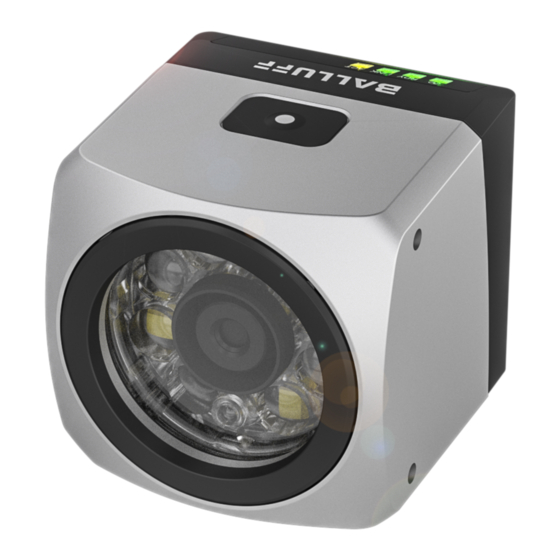
BVS ID-M1280_F1-MB- _ _ _
BVS VS-M1280_F1-MB-_ _ _
Kurzanleitung
Gültigkeit
Diese Anleitung beschreibt die Inbetriebnahme der Senso-
ren BVS ID und BVS VS und gilt für folgende Varianten:
Bestell-
Typ
code
BVS0063 BVS ID-M1280BF1-
MB-000
BVS0064 BVS ID-M1280CF1-
MB-000
BVS0066 BVS ID-M1280CF1-
MB-070
BVS01ZF BVS VS-M1280BF1-
MB-000
BVS01ZH BVS VS-M1280CF1-
MB-000
BVS01ZJ BVS VS-M1280CF1-
MB-070
Eine ausführliche Betriebsanleitung und weitere Informatio-
nen finden Sie unter www.balluff.com.
Zur sicheren Bedienung müssen die in der Be-
triebsanleitung enthaltenen Warn- und Sicherheits-
hinweise gelesen und beachtet werden.
Anschlüsse
1
4
Anschluss
Funktion
Power
Betriebsspannung des Sensors
XF1
Multi-Feldbus
I/O Light
Zwei I/O-Signale und Betriebsspannungsausgang
XF2 / IIoT
Bindet den Sensor in ein lokales Netzwerk ein.
Pinbelegung
Power
Stecker M12, 4-polig, A-codiert
Pin
Signal
1
+24V
2
Trigger In
3
GND
4
SIO
1
deutsch
Beschreibung
1D/2D Code-Sensor, Autofo-
kus, W/R-LED, Multi-Feldbus
1D/2D Code-Sensor, Autofo-
kus, W/IR-LED, Multi-Feldbus
1D/2D Code-Sensor, Auto-
fokus, W/IR-LED, Multi-Feld-
bus, M12 5-pol. L-kodiert
Vision-Sensor, Autofokus,
W/R-LED, Multi-Feldbus
Vision-Sensor, Autofokus, W/
IR-LED, Multi-Feldbus
Vision-Sensor, Autofokus, W/
IR-LED, Multi-Feldbus, M12
5-pol. L-kodiert
1 Power
2 XF1
3 I/O Light
2
4 XF2 / IIoT
3
Funktion
Betriebsspannung
Trigger-Eingang
Masse
SIO als digitaler
Ausgang
Pinbelegung (Fortsetzung)
MOB-Feldbus Variante (-070)
Buchse M12, 5-polig, L-codiert
Pin
Signal
1
V++
2
NC
3
0 V, US
4
NC
5
GND
Die digitalen Sensoreingänge entsprechen der
Richtlinie über Eingänge EN 61131-2, Typ 3.
Jeder Ausgang darf mit maximal 50 mA belastet
werden. Der Gesamtstrom des Moduls darf 4 A pro
Pin nicht überschreiten. Die Last oder Versorgung
muss entsprechend begrenzt werden.
XF1 (Multi-Feldbus)
Buchse M12, 4-polig, D-codiert
Pin
Signal
1
Tx+
2
Rx+
3
Tx-
4
RX-
I/O Light
Buchse M12, 5-polig, A-codiert
Pin
Signal
1
+24V Out
2
Boost / Out
3
GND
4
Light / Out
5
Nicht belegt
XF2 / IIoT (Gigabit Ethernet)
Buchse M12, 8-polig, X-codiert
Pin
Signal
1
BI_DA +
2
BI_DA –
3
BI_DB +
4
BI_DB –
5
BI_DD +
6
BI_DD –
7
BI_DC –
8
BI_DC +
Funktion
Versorgungsspannung US
Nicht angeschlossen
Bezugspotential US
Nicht angeschlossen
Masse
Funktion
Transmit data +
Receive data +
Transmit data -
Receive data -
Funktion
Betriebsspannung
Beleuchtungsboost /
digitaler Ausgang
Masse
Blitzsignal / digitaler
Ausgang
Keine. Pin darf nicht
verwendet werden.
Funktion
Bidirectional data, Pair A +
Bidirectional data, Pair A –
Bidirectional data, Pair B +
Bidirectional data, Pair B –
Bidirectional data, Pair D +
Bidirectional data, Pair D –
Bidirectional data, Pair C –
Bidirectional data, Pair C +
Advertisement

Summary of Contents for Balluff BVS0063
- Page 1 IR-LED, Multi-Feldbus, M12 muss entsprechend begrenzt werden. 5-pol. L-kodiert Eine ausführliche Betriebsanleitung und weitere Informatio- XF1 (Multi-Feldbus) nen finden Sie unter www.balluff.com. Buchse M12, 4-polig, D-codiert Zur sicheren Bedienung müssen die in der Be- Signal Funktion triebsanleitung enthaltenen Warn- und Sicherheits- hinweise gelesen und beachtet werden.
- Page 2 Der Sensor stellt jetzt automatisch die Helligkeit, den des Gerätes. Die aktuelle Firmware-Version ist auf Fokus ein. Der Vorgang dauert ca. zwei Minuten. Hierzu www.balluff.com im Produktbereich verfügbar. wird der Sensor einige Male aufblitzen. Sobald der Auto-Setup-Prozess abgeschlossen ist, wird Neben dem Sensor wird folgendes benötigt:...
- Page 3 5-pin M12 plug, L-coded the BVS ID and BVS VS sensors: Order Type Description Signal Function code Operating voltage US BVS0063 BVS ID-M1280BF1- 1D/2D code sensor, autofo- Not connected MB-000 cus, w/r light, multi-fieldbus 0 V, US Reference potential US BVS0064...
- Page 4 Now, the sensor automatically sets the brightness, www.balluff.com in the product section. the focus. The process will take approx. 2 minutes. In Startup doing so, the sensor will flash several times.


Need help?
Do you have a question about the BVS0063 and is the answer not in the manual?
Questions and answers