Table of Contents
Advertisement
Quick Links
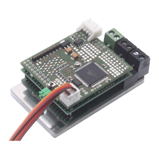
TVC-B10
TVC-B10
10A dual speed controller RC tracked vehicles
The controller contains all components for controlling two DC motors in a
tracked vehicle.
The behavior of the integrated mixer can be set for different vehicle types.
The controller can thus be set for full tracks, half tracks and wheeled ve-
hicles with differential drive. In addition, there are variants for historical
tracked vehicles without tableturn as well as the possibility of inertia simu-
lation.
The controller is equipped with BEC and has an EMK brake, which is released
in the middle position of the throttle and steering stick. The braking effect
can be set either via an RC channel, or fixed.
1
© SGS electronic 2006-2023
Advertisement
Table of Contents

Related Manuals for SGS electronic TVC-B10


Summary of Contents for SGS electronic TVC-B10
- Page 1 The controller is equipped with BEC and has an EMK brake, which is released in the middle position of the throttle and steering stick. The braking effect can be set either via an RC channel, or fixed. © SGS electronic 2006-2023...
-
Page 2: Note
Always switch off power when working on the wiring. Especial take care when connecting more than one receiver energy source. Prevent the device from getting wet. Check loads before connecting them to the modul at a current limited, or fuse protected source. © SGS electronic 2006-2023... -
Page 3: Table Of Contents
8.4 Contact ........20 © SGS electronic 2006-2023... - Page 4 Error codes ....... . 13 list of optional mixing functions available ... . . 15 Abbrevation for the manipulators in the transmitter housing 17 © SGS electronic 2006-2023...
-
Page 5: Introduction
MOSFET push-pull output stages with integrated charge pump. Under normal ambient conditions, a continuous current of 10A is achieved. The controller operates with a PWM frequency of 16kHz. reicht. Der Regler arbeitet mit einer PWM-Frequenz von 16kHz. © SGS electronic 2006-2023... -
Page 6: Scope Of Delivery
2.3 options • 10 controllable light outputs for brake light, reverse light, turn signal, warning light, RKL, low beam and high beam. • Lipo single cell monitoring • RC channel adjustable standstill brake © SGS electronic 2006-2023... -
Page 7: Functional Description
The control of the turn signals is derived from this channel. It is usually connected to the steering channel with a V-cable, parallel to the steering servo. If the channel is not connected, the turn signals only function as warning turn signals. © SGS electronic 2006-2023... -
Page 8: Einbau
The motors must be radio interference suppressed, as is usual in model building. 4.3 Connecting the servo cables The controller is equipped with JR servo cables. The pinout is shown in figure 2. © SGS electronic 2006-2023... -
Page 9: Bec Jumpers
If the jumpers are inserted horizontally (or are not inserted), the voltage is not passed on. In this case, another module must supply the receiver with power. © SGS electronic 2006-2023... -
Page 10: Scalebus Operation (Optional)
If no jumper is plugged in, the information of the drives is output. If coding bridges are plugged into servo cables 1 or 2, the motor outputs © SGS electronic 2006-2023... - Page 11 Controller works as tower control (barrel elevation and tower rota- tion) It is of course possible to connect several controllers to the scale bus. It is also possible for two controllers to output the same information. © SGS electronic 2006-2023...
-
Page 12: Commissioning
(connecting line from motor 1 to motor 2 and vice versa). 3. The directional control is set to neutral, but the model does not drive straight ahead: Correct with steering trim © SGS electronic 2006-2023... -
Page 13: Emf Brake
LED lights up. All error conditions lead to the motor being switched off. blink fault Acknowledgement / Troubleshooting code 2 times no signal from re- Check receiver and connections / elimi- ceiver nate radio interference 3 times overtemperature allow controller to cool down Table 2: Error codes © SGS electronic 2006-2023... -
Page 14: Changing The Mixing Function
4. For example, if the red LED flashes three times, mixer number three of the table is selected. save this, hold the sticks in position and press the button again. 5. Then release the stick. Now the mixer is selected and saved. © SGS electronic 2006-2023... -
Page 15: List Of Optional Mixing Functions Available
Tamiya but when cornering the turn machinery and chain does not run backwards. tanks full track simulation tracked con- superposition struction gearbox 100% machines, inertia modern simulation tanks, snow groomers Table 3: list of optional mixing functions available © SGS electronic 2006-2023... -
Page 16: Glossary Of Terms
Scalebus The Scalebus is a development of SGS electronic to connect con- trollers and modules to compose solutions for complex RC models. -
Page 17: Abbrevation For The Manipulators In The Transmitter Housing
Switch Three Stage switch with three stages Switch Potentiometer linear- or rotary knob PotC Potentiometer linear- or rotary knob with a center key with Center key Table 4: Abbrevation for the manipulators in the transmitter housing © SGS electronic 2006-2023... -
Page 18: Technical Data
6,5 to 24 V Allowable BEC current 1000mA short term, 600mA at 12V, 300mA at 24V PWM frequency 16kHz Typical maximum power dissipation 5 Watt Typical voltage drop in the output 0,15 Volt stage Dimens 75x47x30mm software version © SGS electronic 2006-2023... -
Page 19: Important
Electronic devices do not belong in household waste. © SGS electronic 2006-2023... -
Page 20: Address
We reserve the right to make updates, changes or additions to the infor- mation and data provided. The documentation that accompanies your product applies. Please note that documents obtained later via download may not corre- spond to the status of your module. © SGS electronic 2006-2023...
Need help?
Do you have a question about the TVC-B10 and is the answer not in the manual?
Questions and answers