Table of Contents
Advertisement
Quick Links
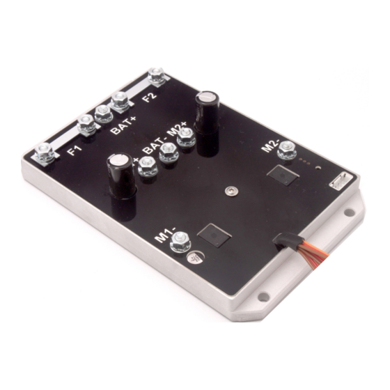
TVC-B100
TVC-B100
100A dual speed controller for RC tracked vehicles
The controller contains all components for controlling two DC motors in a
tracked vehicle.
The behavior of the integrated mixer can be set for different vehicle types.
The controller can thus be set for full tracks, half tracks and wheeled
vehicles with differential drive. In addition, there are variants for historical
tracked vehicles without tableturn as well as the possibility of an inertia
simulation.
The controller has an adjustable EMF standstill brake, which is triggered in
the center position of the throttle and steering stick.
1
© SGS electronic 2006-2023
Advertisement
Table of Contents

Related Manuals for SGS electronic TVC-B100


Summary of Contents for SGS electronic TVC-B100
- Page 1 In addition, there are variants for historical tracked vehicles without tableturn as well as the possibility of an inertia simulation. The controller has an adjustable EMF standstill brake, which is triggered in the center position of the throttle and steering stick. © SGS electronic 2006-2023...
-
Page 2: Note
Always switch off power when working on the wiring. Especial take care when connecting more than one receiver energy source. Prevent the device from getting wet. Check loads before connecting them to the modul at a current limited, or fuse protected source. © SGS electronic 2006-2023... -
Page 3: Table Of Contents
7.6 Documentation ......19 List of Figures Connections overview ......© SGS electronic 2006-2023... - Page 4 Error codes ....... . 11 list of optional mixing functions available ... . . 14 Abbrevation for the manipulators in the transmitter housing 16 © SGS electronic 2006-2023...
-
Page 5: Introduction
The controller operates with a PWM frequency of 16kHz. . To prevent ground loops and resulting interference, the servo inputs are galvanically isolated. Accordingly, the receiver not is supplied by the controller. The housing of the controller is CNC milled from aluminum. © SGS electronic 2006-2023... -
Page 6: Installation
High, high-frequency currents flow between the drive battery in both directions. Provide a low-resistance connection between the drive battery and the controller and use a suitable switch or a high-current relay. Use only fuses for protection. We strongly advise against the © SGS electronic 2006-2023... -
Page 7: Connecting The Receiver
The receiver is therefore not supplied with power from the controller, but must be supplied from another power source. This is usually from a receiver battery. The input circuit also requires the receiver supply voltage (approx. 15mA) and obtains this from the receiver © SGS electronic 2006-2023... -
Page 8: Emf Brake
If you move the throttle in one direction the on phase of the yellow LED gets longer and longer, in the other direction shorter and shorter until it is completely off. The stronger the lever deflection, the faster the © SGS electronic 2006-2023... - Page 9 If you press the button again, the brake setting is saved and is retained even after switching off and on again. function Error (overtemperature, overcurrent,short circuit) yellow EMF Brake Brake effect (flashes with variable duty cycle) ;In Scalebus mode it is permanently on green operating status Table 1: LED-Codes © SGS electronic 2006-2023...
-
Page 10: Commissioning
It indicates these error conditions by flashing the green LED (blink code) and lighting the red LED. Special attention should be paid to the overvoltage error during regenera- tive power supply. A regenerative overvoltage fault is triggered when the © SGS electronic 2006-2023... -
Page 11: Correct Driving Direction
The direction of travel depends on the mechanical arrangement of the engines in the vehicle. Usually, the motors are mounted so that the motor shafts are in opposite directions. As a result, the motors must be connected © SGS electronic 2006-2023... -
Page 12: Scalebus Operation
(white, four-pin connector). For example, the FO module TVC-MF-10 can control the controller. The controller switches to Scalebus mode if there is no servo signal on the servo cables when it is switched on. © SGS electronic 2006-2023... -
Page 13: Changing The Mixing Function
4. For example, if the red LED flashes three times, mixer number three of the table is selected. save this, hold the sticks in position and press the button again. 5. Then release the stick. Now the mixer is selected and saved. © SGS electronic 2006-2023... - Page 14 Tamiya but when cornering the turn machinery and chain does not run backwards. tanks full track simulation tracked con- superposition struction gearbox 100% machines, inertia modern simulation tanks, snow groomers Table 3: list of optional mixing functions available © SGS electronic 2006-2023...
-
Page 15: Glossary Of Terms
Scalebus The Scalebus is a development of SGS electronic to connect con- trollers and modules to compose solutions for complex RC models. - Page 16 Switch Three Stage switch with three stages Switch Potentiometer linear- or rotary knob PotC Potentiometer linear- or rotary knob with a center key with Center key Table 4: Abbrevation for the manipulators in the transmitter housing © SGS electronic 2006-2023...
-
Page 17: Technical Data
Supply voltage servo input 3.3V to 8.0V PWM frequency 16kHz Typical maximum power dissipation Typical voltage drop in power stage 0.15V Dimensions (height without connectors) 17mm distance screws row 154mm Screw spacing 35mm Bore diameter 5.2mm Software version 02.01.20 © SGS electronic 2006-2023... -
Page 18: Important
Electronic devices do not belong in household waste. © SGS electronic 2006-2023... -
Page 19: Address
We reserve the right to make updates, changes or additions to the infor- mation and data provided. The documentation that accompanies your product applies. Please note that documents obtained later via download may not corre- spond to the status of your module. © SGS electronic 2006-2023... - Page 20 TVC-B100 © SGS electronic 2006-2023...
Need help?
Do you have a question about the TVC-B100 and is the answer not in the manual?
Questions and answers