Table of Contents
Advertisement
Quick Links
GEA Bock EX-HG12P
Assembly instructions
09691-08.2019-Gb
Translation of the original instructions
EX-HG12P75-4
EX-HG12P/90-4
EX-HG12P/110-4
EX-HG12P/60-4 S
EX-HG12P/75-4 S
EX-HG12P/90-4 S
EX-HG12P/110-4 S
Device category 2 G
acc. to directive 2014/34/EU
EX-HGX12P/75-4
EX-HGX12P/90-4
EX-HGX12P/110-4
EX-HGX12P/60-4 S
EX-HGX12P/75-4 S
EX-HGX12P/90-4 S
EX-HGX12P/110-4 S
EX-HG12P/75-4 HC
EX-HG12P/90-4 HC
EX-HG12P/110-4 HC
EX-HG12P/60-4 S HC
EX-HG12P/75-4 S HC
EX-HG12P/90-4 S HC
EX-HG12P/110-4 S HC
Advertisement
Table of Contents

Related Manuals for GEA pluscom Bock EX-HG12P


Summary of Contents for GEA pluscom Bock EX-HG12P
- Page 1 GEA Bock EX-HG12P Assembly instructions Device category 2 G acc. to directive 2014/34/EU 09691-08.2019-Gb Translation of the original instructions EX-HG12P75-4 EX-HGX12P/75-4 EX-HG12P/75-4 HC EX-HG12P/90-4 EX-HGX12P/90-4 EX-HG12P/90-4 HC EX-HG12P/110-4 EX-HGX12P/110-4 EX-HG12P/110-4 HC EX-HG12P/60-4 S EX-HGX12P/60-4 S EX-HG12P/60-4 S HC EX-HG12P/75-4 S...
-
Page 2: Table Of Contents
Observe the safety instructions contained in these instructions. These instructions must be passed onto the end customer along with the unit in which the compressor is installed. Manufacturer GEA Bock GmbH 72636 Frickenhausen Contact GEA Bock GmbH Benzstraße 7... - Page 3 Contents Page Areas of application 3.1 Approved refrigerant 3.2 Important information on the use of hydrocarbons 3.3 Oil charge 3.4 Limits of application Compressor assembly 4.1 Ignition source control of the compressor 4.2 Storage and transport 4.3 Setting up 4.4 Pipe connections 4.5 Pipes 4.6 Laying suction and pressure lines 4.7 Operating the shut-off valves...
-
Page 4: Safety
1| Safety 1.1 Identification of safety instructions: DANGER Indicates a dangerous situation which, if not avoided, will cause immediate fatal or serious injury. WARNING Indicates a dangerous situation which, if not avoided, may cause fatal or serious injury. CAUTION Indicates a dangerous situation which, if not avoided, may cause fairly severe or minor injury. -
Page 5: Safety Instructions
The declarations and remarks by GEA can only refer to the product itself. We assume that the appli- cable regulations, standards and technical rules are followed in installation and during operation. The plant constructor/operator must evaluate the interactions with other devices and components of the system and with the environment, especially regarding potential ignition sources. -
Page 6: Intended Use
Likewise, all accessories available from, approved and specially marked by GEA are exclusively approved, according to their intended use, for attachment to and operation with GEA compressors of appliance category 2 in accordance with Directive 2014/34/EU. -
Page 7: Product Description
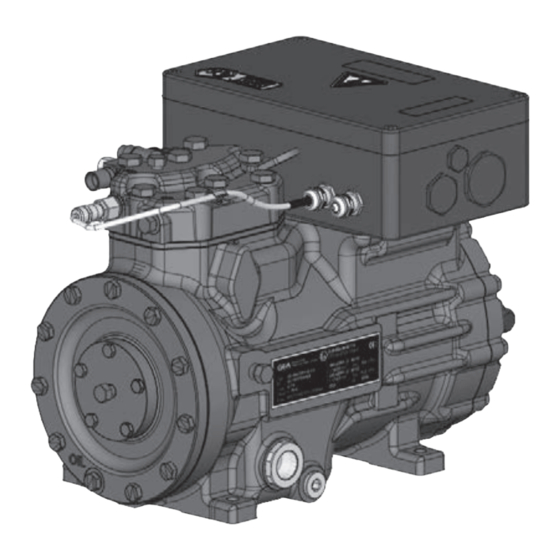
2 | Product description 2.1 Short description • Semi-hemetic two-cylinder reciprocating compressor with oil pump lubrication • Suction-gas-cooled drive motor • For use in explosion-endangered areas Transport eyelet Cylinder cover Valve plate Name plate Oil pump Oil sight glass Fig. 1 Terminal box Discharge shut-off valve... - Page 8 2 | Product description 2.2 Ignition protection concept In accordance with Directive 2014/34/EU, GEA ATEX compressors are suitable for use in device category 2 for explosive gas atmospheres up to temperature class T3 and explosion hazard subgroup IIB/IIC. The entire compressor, including motor, is perceived as technically tight and therefore does not need an ignition protection.
- Page 9 2 | Product description Accessories Heating elements for the compressors to protect against explosion risks are designed in the protection types increased safety (Ex d) and have to have to be mounted stationary at the designated areas in the compressor housing. The heating elements can be operated without temperature- and oil level control since the thermal type testing by the manufacturer verified that the heating elements prevent the exceeding of the temperature class of the compressor.
-
Page 10: Type Key
2 | Product description 2.3 Name plate (example) 2.2 Name plate (example) II 2G Ex d e ia IIC T3 Gb / EPS 16 ATEX 1095 X EX-HG12P/110-4 S AY15595A008 6,1 A 26 A 11,3 IP66 Fig. 3 Type designation Voltage, circuit, frequency 50 Hz Machine number Nominal rotation speed... -
Page 11: Atex-Identification
2 | Product description 2.5 ATEX identification Ex d e ia IIB/IIC T3 Gb Equipment protection level Temperature class T3 (max.200 °C) Explosion subgroups, IIB = Offshore paint finish IIC = ESD paint finish Intrinsically safe equipment Increased safety Flameproof enclosure, heater (option) Europ. explosion protection acc. to Direc. 2014/34/EU Suitability for gas-explosive area Device category 2 (= zone 1) Explosion group II for Ex-endangered areas (not underground buildings) -
Page 12: Areas Of Application
It should be noted that the solubility of hydrocarbons in oil can be very high, especially at high suction pressures. A high-viscosity lubricant may be required, depending on the application and experience. The lubricant must be released for use by GEA. Depending on the application, a pump-down switch should also be added (e.g. when the refrigeration system is set up outside). -
Page 13: Oil Charge
3 | Areas of application 3.3 Oil charge The following refrigerants are approved for the compressor: Refrigerant Oil grade FUCHS Reniso SP 46 R134a, R404A, R507, R407C FUCHS Reniso Triton SE 55 R290, R1270 FUCHS Reniso Synth 68 INFO Used refrigerant oils have to have a self-ignition temperature of >... -
Page 14: Limits Of Application
3 | Areas of application 3.4 Limits of application ATTENTION Compressor operation is possible within the operating limits. These can be found in GEA Bock compressor selection tool (VAP) under vap.gea.com. Observe the information given there. - Max. permissible discharge end temperature 140 °C. -
Page 15: Compressor Assembly
4 | Compressor assembly INFO • New compressors are factory-filled with inert gas. Leave this service charge in the compressor for as long as possible and prevent the ingress of air. • Check the compressor for transport damage before starting any work. • Before starting work, obtain written work release. •... -
Page 16: Storage And Transport
4 | Compressor assembly 4.2 Storage and transport Storage at (−30 °C) - (+70 °C), maximum permissible relative humi- dity 10 % - 95 %, no condensation Do not store in a corrosive, dusty, vaporous atmosphere or in a com- Fig. 5 bustible environment. Use transport eyelet. Do not lift manually! Use lifting gear! Fig. -
Page 17: Pipe Connections
4 | Compressor assembly 4.4 Pipe connections The pressure and suction shut-off valves have graduated inside diameters so that pipes in the common millimeter and inch dimensions can be used. The pipe will be inserted more or less deep, depending on the dimension. -
Page 18: Operating The Shut-Off Valves
4 | Compressor assembly 4.7 Operating the shut-off valves Before opening or closing the shut-off valve, release the valve spindle seal by approx. of a turn counter-clockwise. After activating the shut-off valve, re-tighten the adjustable valve spindle seal clockwise. Release Tighten Valve spindle seal Fig. -
Page 19: Electrical Connection
5 | Electrical connection Electrical connection DANGER Risk of electric shock! High voltage! Only carry out work when the electrical system is disconnected from the power supply! ATTENTION When attaching accessories with an electrical cable, a minimum bending radius of 3 x the cable diameter must be maintained for laying the cable. -
Page 20: Potential Equalization
5 | Electrical connection 5.1 Potential equalization Before start-up, the potential equalisation must be connected (see Fig. 18). INFO Special attention must be paid to sufficient conductivity of all contact points. There must be a large seat (e.g. with ring cable lug). The installed voltage equalization must be secured against loosing and firmly connected to earth Potential equalization connection Fig. 18 5.2 Information for contactor and motor contactor selection WARNING Always install all electrical peripheral devices in an external control cabinet outside the explosion-endangered area! All protection devices and switching or monitoring units must be fitted in accordance with the local safety regulations and established specifications (e.g. VDE) as well as with the manufacturer’s infor-... -
Page 21: Terminal Cross Section For Leads
5 | Electrical connection 5.3 Terminal cross section for leads To limit the heating of conducting parts, the minimum terminal cross sections, indicated in the table have to be followed. Compressor type Minimum terminal cross section EX-HG(X)12(P)(e)/60-4 S (HC) 3 x 1,5 mm² EX-HG(X)12(P)(e)/75-4 (HC) 3 x 1,5 mm²... -
Page 22: Circuit Diagram Direct Start
5.5 Circuit diagram direct start Y Legend Main switch Fault protection switch (release current 30 mA) FC1.1 Motor safety switch FC2.1 Control fuse Control voltage O/I Performance contactor (only star connection allowed!) Compressor motor Cold conductor (PTC-sonsor) motor winding Thermal protection thermostat BT3¹ Pump down- pressostat/ thermostat or external enabling switch BP1/BP2¹... - Page 23 FC2.2 FC1.1 FC2.1 INT69 EX2 INT69G EX I> I> I> FC1.1 Δ 4 PA network Netz 400V 50Hz P< P> Der Schaltplan ist nur ein Systemschema, zur Anordnung und Reihenfolge The circuit diagram is a system scheme for assignment and order of the safety chain, without ˜...
-
Page 24: Electronic Trigger Unit Int69 Ex2
5 | Electrical connection 5.6 Electronic trigger unit INT69 EX2 ATTENTION Install INT69 EX2 outside the explosion-endangered area. The INT69 EX2 trigger unit must be installed according to the wiring diagram. The compressor motor is fitted with cold conductor temperature sensors (PTC) con- nected to the electronic trigger unit INT69 EX2. - Page 25 5 | Electrical connection 5.7 Connection of the trigger unit INT69 EX2 Wire the PTC temperature sensor of the compressor motor, heat protection thermostats of the cylinder head, pressure and temperature monitoring of the system according to the wiring diagram (fig. 19). Pay attention for connecting the PTC sensor. Terminals 1 + 2 on the trigger unit INT69 EX2 and terminals PTC 1 and PTC 2 on the compres- sor terminal board must not come into contact with mains voltage. This would destroy the trigger unit and PTC sensors The supply voltage at L1-N (+/- for DC 24 V version) must be identical to the voltage at terminals 11, 12 and 14.
-
Page 26: To Verify The Intrinsic Safety Of The Ptc Hot Gas Sensor
5 | Electrical connection 5.9 To verify the intrinsic safety of the PTC hot gas sensor To verify the intrinsic safety of the hot gas sensor, the following values must be rated: Thermal protection thermostat (item no. 50159, retrofit kit item no. 08860) Conditions for intrinsic safety [ V ] ≤... -
Page 27: Preparations For Start-Up
6 | Commissioning WARNING All of the following work must be performed only by qualified perso- nnel (see p. 4) and with exclusion of an explosive atmosphere. 6.1 Preparations for start-up INFO In order to protect the compressor against prohibited operating conditions, high- and low-pressure monitors are necessary in ac- cordance with the relevant national regulations! The compressor has undergone trials in the factory and all functions have been tested. -
Page 28: Refrigerant Charge
6 | Commissioning 6.5 Refrigerant charge CAUTION Wear personal protective clothing such as goggles and protective gloves! Make sure that the suction and pressure line shut-off valves are open. With the compressor switched off, add the liquid refrigerant directly to the condenser or receiver, breaking the vacuum. If the refrigerant needs topping up after starting the compressor, it can be topped up in vapour form on the suction side, or, taking suitable precautions, also in liquid form at the inlet to the evaporator. -
Page 29: Preventing Icing On The Compressor
6 | Commissioning 6.8 Preventing icing on the compressor Check compressor regularly for icing! Icing/condensate formation in the terminal box of the compressor must be prevented through suitable measures (e.g. suction gas overheating). 7 | Maintenance 7.1 Preparation WARNING All work must be performed only by: qualified personnel (see page 4) with exclusion of any danger of explosion. -
Page 30: Spare Part Recommendation
80361 80362 Set of gaskets 80359 Only use original GEA spare parts! Information on available replacement parts can be obtained from the replacement parts list. Further repair work can only be carried out at the factory. INFO I f system function must be guaranteed with certainty, we recom- mend a standby compressor. -
Page 31: Accessories
8| Accessories 8.1 Oil sump heater (retrofit kit item no. 80880) INFO Use of the heating element in accordance with IECEx compressor approval is not permitted. The explosion-proof heating element of the company Elmess, type DHK 60M05/P-0,08-T3 is sup- plied with an electrical supply line of 3 metres. The heating element is enclosed with the compressor, separately packed as protection against damage during transportation, and must be assembled at the installation site of the compressor. -
Page 32: Technical Data
9| Technical data Oil charge (sight glass centre) Oil charge (ex works) Suction line Discharge line Weight Starting current (rotor locked) Max. power consumption Max. operating current 380-420 V Y - 3 - 50 Hz Voltage 440-480 V Y - 3 - 60 Hz Displacement (1450 / 1740 rpm) No. -
Page 33: Dimensions And Connections
10| Dimensions and connections EX-HG12P M16x1,5 Centre of gravity M25x1,5 M32x1,5 ¹ 4x 10 Anschlüsse / Connections Saugabsperrventil, Rohr (L)* mm / Zoll 16 - 5/8“ Suction line valve, tube (L)* mm / inch Druckabsperrventil, Rohr (L)* mm / Zoll 12 - 1/2“... - Page 34 10| Dimensions and connections Suction line see technical data, Chapter 9 Discharge line 1 / 8 “ NPTF Connection suction side, not lockable 7 / 16 “ UNF Connection suction side, lockable 1 / 8 “ NPTF Connection discharge side, not lockable 7 / 16 “...
- Page 35 10| Dimensions and connections Dimensions INT69 EX2 for switch cabinet installation Length: 68 mm Width: 33 mm Height: 53 mm Dimensions with accessory parts Fig. 22 Oil sump heater...
-
Page 42: Service
Dear customer, GEA compressors are top-quality, reliable and service-friendly quality products. If you have any questions about installation, operation and accessories, please contact our technical service or specialist wholesaler and/or our representative. The GEA service team can be contacted by phone with a toll-free hotline 00 800 / 800 000 88 or via e-mail: info@gea.com Yours faithfully GEA Bock GmbH Benzstraße 7... - Page 44 • • GEA Group is a global engineering company with multi-billion euro sales and operations in more than 50 countries. Founded in 1881, the company is one of the largest providers of innovative equipment and process technology. GEA Group is listed in the STOXX ®...
Need help?
Do you have a question about the pluscom Bock EX-HG12P and is the answer not in the manual?
Questions and answers