Code Blue CB 2 Series Admin Manual
Hide thumbs
Also See for CB 2 Series:
- Administrator's manual (63 pages) ,
- Administrator's manual (31 pages) ,
- Administrator's manual (33 pages)

Related Manuals for Code Blue CB 2 Series


Summary of Contents for Code Blue CB 2 Series
- Page 1 CB 2 Series Model: ENBS06, ENBS07, ENBS08, ENBS09, ENBS10, ENBS15 Admin Guide Installation | Configuration | Support | Maintenance | Use 800.205.7186 • www.codeblue.com...
- Page 2 OF OR IN CONNECTIONS WITH THIS GUIDE, THE SOFTWARE OR OTHER INFORMATION CONTAINED HEREIN OR THE USE THEREOF. Code Blue Corporation reserves the right to make any modifications to this guide or the information contained herein at any time without notice. The software described herein may also be governed by the terms of a separate user license agreement.
-
Page 3: Table Of Contents
CB 2 Series Administrator Guide Table of Contents Section Section Title Page # Introduction Model Photos Dimensions Safety Information Installation Instructions Tools Needed CB 2-a Installation Instructions CB 2-e Installation Instructions CB 2-s Installation Instructions CB 2-ap (Audio Paging) Installation Instructions... -
Page 4: Introduction
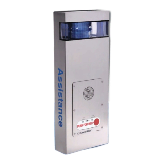
2 Introduction Thank you for choosing the CB 2 Series wall mount for your Code Blue application. CB 2 Series has a rugged steel construction, shatterproof Lexan Lens, industrial engineering grade reflective graphics and weather, UV and graffiti resistant paint, and is illuminated by a high-powered, 270 lumens/92 candela LED blue beacon/strobe. -
Page 5: Dimensions
CB 2 Series Administrator Guide 3 Dimensions CB 2-a page 5 of 43 GU-149-Z1 Code Blue • 259 Hedcor Street • Holland, MI 49423 USA • 800.205.7186 • www.codeblue.com... - Page 6 CB 2 Series Administrator Guide CB 2-ap 4.00 11.90 2.00 1.50 3.70 29.80 26.00 23.99 11.75 .44 TYP 2.29 3.34 1.45 9.00 8.50 FRONT VIEW BACK VIEW SIDE VIEW 3.64 page 6 of 43 GU-149-Z1 Code Blue • 259 Hedcor Street •...
- Page 7 CB 2 Series Administrator Guide CB 2-e page 7 of 43 GU-149-Z1 Code Blue • 259 Hedcor Street • Holland, MI 49423 USA • 800.205.7186 • www.codeblue.com...
- Page 8 CB 2 Series Administrator Guide CB 2-s page 8 of 43 GU-149-Z1 Code Blue • 259 Hedcor Street • Holland, MI 49423 USA • 800.205.7186 • www.codeblue.com...
- Page 9 CB 2 Series Administrator Guide CB 2 with AED 11.24 3.375 8.00 4 .86 5.00 5.00 8.50 5.11 11.75 46.72 39.00 1.13 39.16 18.00 24.00 22.31 3.00 3.36 15.50 3.25 9.00 FRONT VIEW SIDE VIEW BACK VIEW 1.73 1.13 8.00 3.88...
-
Page 10: Safety Information
In some countries, a certified electrician may be required. NOTICE When transporting a Code Blue product, use the original packaging or equivalent to prevent damage to the product. Code Blue products shall be used in compliance with local laws and regulations. -
Page 11: Installation Instructions
Important Notes: EIA/TIA, ANSI, CSA and BICSI cabling or similar standards shall be adhered to for proper operation of Code Blue communication devices connected to copper or fiber infrastructures communications cable and electrical cable in the same conduit is not an acceptable installation and shall not be supported. -
Page 12: Cb 2-A Installation Instructions
CB 2 Series Administrator Guide CB 2-a Installation Instructions 1. Unscrew security screw from bottom of unit. Lift and open unit. 2. Disconnect wire connections from strobe, faceplate light and phone. Lift up on black locking tab on each connector to separate. - Page 13 CB 2 Series Administrator Guide CB 2-a Mounting Schematic 9.00 28.21 1.25 26.00 2.21 DISCLAIMER: The dimensions above are intended as guidelines only. For specific installation requirements, reference your local codes. All wiring must be installed and connected by experienced and certified personnel to meet local and national electrical codes, and will include a service disconnect.
-
Page 14: Cb 2-E Installation Instructions
CB 2 Series Administrator Guide CB 2-e Installation Instructions 1. Unscrew security screw from bottom of unit. Lift and open unit. 2. Disconnect wire connections from strobe, faceplate light and phone. Lift up on black locking tab on each connector to separate. - Page 15 CB 2 Series Administrator Guide CB 2-e Mounting Schematic 9.00 28.21 1.25 26.00 2.21 DISCLAIMER: The dimensions above are intended as guidelines only. For specific installation requirements, reference your local codes. All wiring must be installed and connected by experienced and certified personnel to meet local and national electrical codes, and will include a service disconnect.
-
Page 16: Cb 2-S Installation Instructions
CB 2 Series Administrator Guide CB 2-s Installation Instructions 1. Unscrew security screw from top of unit. Lift and open unit. 2. Open or remove the unit shell. Open: Allow top of shell to fall open while base of the shell remains in contact with base of backplate. - Page 17 CB 2 Series Administrator Guide CB 2-s Mounting Schematic 12 REF 4 X Ø7/16 MOUNTING HOLES 30 3/4 42 REF 2 X Ø1-1/8 (KNOCKOUTS FOR Ø3/4 CONDUIT) 2 9/16 8 5/16 REF 1 1/2 REF 1 1/2 GROUND/FLOOR Suggested installation dimensions shown from ground to lower right mounting hole are for single button faceplates.
-
Page 18: Cb 2-Ap (Audio Paging) Installation Instructions
CB 2 Series Administrator Guide CB 2-ap (Audio Paging) Installation Instructions 1. Unscrew security screw from bottom of unit. Lift and open unit. 2. Disconnect wire connections from strobe, faceplate light and phone. Lift up on black locking tab on each connector to separate. - Page 19 CB 2 Series Administrator Guide CB 2 with Audio Paging (CB 2-ap) Mounting Schematic DISCLAIMER: The dimensions above are intended as guidelines only. For specific installation requirements, reference your local codes. All wiring must be installed and connected by experienced and certified personnel to meet local and national electrical codes, and will include a service disconnect.
-
Page 20: Alternative Mounting Options
CB 2 Series Administrator Guide 6 Alternative Mounting Options Pole Mounting Kit Installation Instructions IMPORTANT NOTE: Minimum Pole Diameter: 4.0" THREAD MOUNTING STRAPS THROUGH SLOTS Thread mounting straps(4) through slots on pole mount bracket(1). HOLD BRACKET TO POLE Set the height of the bracket(1) so that the speakerphone push button(s) on the unit will be at desired height (please check with local codes for ADA compliance). -
Page 21: How To Update Connectors
Administrator Guide 7 How to Update Connectors As of 2020, many Code Blue products come with Wago connectors. These connectors provide ease of use and a much stronger connection. Below are the steps needed to change to the new connectors. - Page 22 CB 2 Series Administrator Guide page 22 of 43 GU-149-Z1 Code Blue • 259 Hedcor Street • Holland, MI 49423 USA • 800.205.7186 • www.codeblue.com...
-
Page 23: Remote Mount Beacon/Strobe Installation
CB 2 Series Administrator Guide 8 Remote Mount Beacon/Strobe Installation ATTACH J-BOX TO THE POLE Thread the banding (B) through the pole bracket (A) located on the backside of the J-box (C). Wrap the banding around the pole. Cut the banding to desired length. -
Page 24: Strobe Management Instructions
CB 2 Series Administrator Guide Strobe Management Instructions S-2000 (for CB 2-a, CB 2-ap, & CB 2-e ONLY) POSITIVE (12-24V DC or AC) BLACK COMMON (GROUND) YELLOW (FLASH MODE) S-1000 YELLOW (FLASH MODE) DRY CONTACT POSITIVE (12-24V DC or AC) CLOSED = "ON"... -
Page 25: Strobe Programming
CB 2 Series Administrator Guide PROGRAMMING PRIMARY & SECONDARY MODES 1. Remove power from unit. 2. Short the Yellow wires together. 3. Restore power to the unit and wait until the unit begins to flash. Once the unit begins to flash, remove the short. The unit will alternately demonstrate the Secondary-Flash Mode and Primary-Steadyburn Mode that will be displayed during operation. -
Page 26: Aed Access And Maintenance Guide
Additional AED Housing key fobs are available under Part #41107. Each Code Blue unit can sync up to 40 different fobs. If a new user key fob is added, then the rule is “first in, first out”. For example, No. 41 will push out the first user of the system. -
Page 27: Power Requirements
CB 2 Series Administrator Guide 10 Power Requirements The following tables on pages 27-30 include CB 2 Series and ALL OTHER Code Blue devices & enclosures for reference. page 27 of 43 GU-149-Z1 Code Blue • 259 Hedcor Street •... - Page 28 CB 2 Series Administrator Guide page 28 of 43 GU-149-Z1 Code Blue • 259 Hedcor Street • Holland, MI 49423 USA • 800.205.7186 • www.codeblue.com...
- Page 29 CB 2 Series Administrator Guide page 29 of 43 GU-149-Z1 Code Blue • 259 Hedcor Street • Holland, MI 49423 USA • 800.205.7186 • www.codeblue.com...
- Page 30 CB 2 Series Administrator Guide page 30 of 43 GU-149-Z1 Code Blue • 259 Hedcor Street • Holland, MI 49423 USA • 800.205.7186 • www.codeblue.com...
-
Page 31: Wiring Diagrams
CB 2 Series Administrator Guide 11 WIRING DIAGRAMS CB 2-a & CB 2-e 24-277V AC DIN Rail Power System For installations with 24-277V AC incoming power on site. Provides flexibility for future power updates compared to the 24V AC only option. -
Page 32: Cb 2-S 110-347V Ac Standard Wiring With Multi-Tap Transformer (Power Brick)
CB 2 Series Administrator Guide CB 2-s 110-347V AC Standard Wiring with Multi-Tap Transformer (Power Brick) For installations with 110-347V AC incoming power on site. Used in the following configurations: Standard CB 2-s - No Cellular Communication CB 2-s with Cellular Communication... -
Page 33: Cb 2-S 24V Dc Standard Wiring
CB 2 Series Administrator Guide CB 2-s 24V DC Standard Wiring For installations with 24V AC incoming power on site. Used in the following configurations: Standard CB 2-s - No Cellular Communication CB 2-s with Cellular Communication Optional Accessory Beacon Strobe Area Light Cellular Comm. -
Page 34: Cb 2-A & Cb 2-E Poe Standard Din Rail Wiring
CB 2 Series Administrator Guide CB 2-a & CB 2-e PoE Standard DIN Rail Wiring For installations with PoE incoming power on site. Used in the following configurations: Standard CB 2-a - No Cellular Communication Standard CB 2-e - No Cellular Communication... -
Page 35: Cb 2-S Poe Standard Wiring
CB 2 Series Administrator Guide CB 2-s PoE Standard Wiring For installations with PoE incoming power on site. Used in the following configurations: Standard CB 2-s - No Cellular Communication CB 2-s with Cellular Communication Beacon Strobe Area Light Cellular Comm. -
Page 36: Cb 2-Ap Audio Paging Standard Din Rail Wiring
CB 2 Series Administrator Guide CB 2-ap Audio Paging Standard DIN Rail Wiring For installations with 100-240V AC incoming power on site. Used in the following configurations: Standard CB 2-ap - No Cellular Communication CB 2-ap with Cellular Communication AC Incoming Hot, Fused @ 5.0 amps 24VDC AC Incoming Neutral Fused @ 5.0 amps... -
Page 37: Cb 2-Ap Audio Paging Amplifier Wiring & Volume Control
CB 2 Series Administrator Guide CB 2-ap Audio Paging Amplifier Wiring & Volume Control Speaker Located Inside CB 2-ap Unit 12-24V DC This harness comes with the Amp PCB SPKR - SPKR + This harness comes with the Amp PCB... -
Page 38: Locating Unit Serial Numbers
CB 2 Series Administrator Guide 12 Locating Unit Serial Numbers Remove the unit cover, or remove the speakerphone using a security bit. The serial number will be listed on the manufacturer’s label located on the unit’s backplate (1). Please note, this serial number location is the same across all CB2 Models... -
Page 39: Maintenance Schedule
CB 2 Series Administrator Guide 13 Maintenance Schedule LEGEND Guard Tasks Technician Tasks DAILY OR WEEKLY Perform functional communications check. Action: Press Red Button Strobe activates Red LED "Call Placed" light turns on Message plays Call connects, green LED "Call Received" light turns on... - Page 40 The Surface Care Frequency table below provides general guidelines to assist in configuring a schedule. Please note that the frequency of care required to guard the Code Blue unit’s surface from damage will also be dictated by local environmental characteristics.
-
Page 41: Warranty
14 Warranty Code Blue Corporation provides a limited warranty on this product. Refer to your sales agreement to establish the terms. In addition, Code Blue’s standard warranty language, as well as information regarding support for this product while under warranty, is available at www.codeblue.com/support... -
Page 42: Download Information
CB 2 Series Administrator Guide 15 Download Information Code Blue now has a centralized location where you can find installation, setup, information, configuration and operation instructions. Admin Guides: www.codeblue.com/resources/guides Frimware: www.codeblue.com/resources/firmware Maintenance Tips: www.codeblue.com/support Product Sheets: www.codeblue.com/resources/sheets Specifications: www.codeblue.com/resources/specifications These guides should contain all the information needed for your application. If further information is required, please contact customerservice@codeblue.com. -
Page 43: Legal & Regulatory Information
This digital apparatus complies with CAN ICES-3 (Class A). The product shall and fitness for a particular purpose. Code Blue shall not be liable or be connected using a shielded network cable (STP) that is properly responsible for incidental or consequential damages in connection with grounded.
Need help?
Do you have a question about the CB 2 Series and is the answer not in the manual?
Questions and answers