
Related Manuals for Code Blue CB RT Series


Summary of Contents for Code Blue CB RT Series
- Page 1 CB RT Series Model: ENTM01 Admin Guide Installation | Configuration | Support | Maintenance | Use 800.205.7186 • www.codeblue.com...
- Page 2 OF OR IN CONNECTIONS WITH THIS GUIDE, THE SOFTWARE OR OTHER INFORMATION CONTAINED HEREIN OR THE USE THEREOF. Code Blue Corporation reserves the right to make any modifications to this guide or the information contained herein at any time without notice. The software described herein may also be governed by the terms of a separate user license agreement.
-
Page 3: Table Of Contents
CB RT Series Administrator Guide Table of Contents Section Section Title Page # Introduction CB RT Model Photo Dimensions Safety Information Installation Instructions Getting Started Tools Needed CBRT Installation Instructions Anchor Bolt Installation Set the Unit Install Combination Beacon/Strobe Incoming Power Wiring... -
Page 4: Introduction
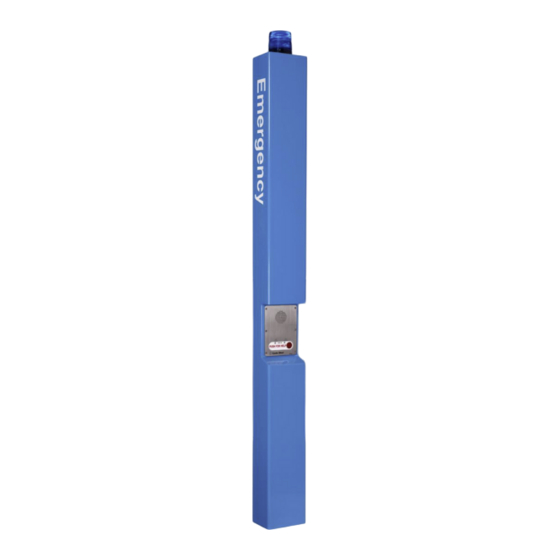
IP and analog phones Overhead Camera Mount This guide contains all of the CB RT tower information. This manual contains a general overview of the Code Blue CB RT Tower options and its application, installation and wiring. CB RT •... -
Page 5: Dimensions
CB RT Series Administrator Guide 3 Dimensions CB RT Code Blue • 259 Hedcor Street • Holland, MI 49423 USA • 800.205.7186 • www.codeblue.com GU-163-D page 5 of 25... -
Page 6: Safety Information
In some countries, a certified electrician may be required. NOTICE When transporting a Code Blue product, use the original packaging or equivalent to prevent damage to the product. Code Blue products shall be used in compliance with local laws and regulations. -
Page 7: Installation Instructions
Important Notes: EIA/TIA, ANSI, CSA and BICSI cabling or similar standards shall be adhered to for proper operation of Code Blue communication devices connected to copper or fiber infrastructures communications cable and electrical cable in the same conduit is not an acceptable installation and shall not be supported. -
Page 8: Cbrt Installation Instructions
CB RT Series Administrator Guide CBRT Installation Instructions FOUNDATION - ANCHOR BOLT INSTALLATION INSTRUCTIONS Conduit – Electrical and communication line conduit should be run through the center of the foundation hole with a maximum combined diameter of three inches. A minimum of four inches and a maximum of six inches of conduit is required above the finished grade level. -
Page 9: Set The Unit
CB RT Series Administrator Guide CBRT Installation Instructions (continued) SET THE UNIT Screw one set of nuts and washers onto the anchor bolts – After the foundation has set, screw one set of nuts followed by one set of washers onto the anchor bolts. -
Page 10: Overhead Camera Mount Installation
CB RT Series Administrator Guide Overhead Camera Mount Installation All CB RT Overhead Camera Mounts Require: • Ladder to reach the top of the unit. • 3/8" Wrench Installing the Overhead Camera Mount The camera mount will come with a gasket already mounted to the bracket on the arm. -
Page 11: Line Power Installation
CB RT Series Administrator Guide Line Power Installation Instructions IMPORTANT: All wiring shall comply with national and local codes governing this installation. It is the responsibility of the installer to ensure these conditions are complied with. SUPPLY WIRING Pulling the power wires – Wire should be a minimum of 14 AWG and be pulled into the unit, leaving a minimum of two feet of wire from the opening of the conduit. -
Page 12: S-1000 & S-1050 Strobe Operation
CB RT Series Administrator Guide S-1000 & S-1050 Strobe Operation NOTE: Instructions pertain to: Model S-1000 LED Beacon/Strobe and Model S-1050 LED Beacon/Strobe only. POSITIVE (12-24V DC or AC) BLACK COMMON (GROUND) YELLOW (FLASH MODE) CONTACT CLOSED = "ON" YELLOW (FLASH MODE) REMOVE ALL POWER FROM UNIT BEFORE SERVICING. -
Page 13: S-1000 & S-1050 Strobe Programming
CB RT Series Administrator Guide PROGRAMMING PRIMARY & SECONDARY MODES 1. Remove power from unit. 2. Short the Yellow wires together. 3. Restore power to the unit and wait until the unit begins to flash. Once the unit begins to flash, remove the short. The unit will alternately demonstrate the Secondary-Flash Mode and Primary-Steadyburn Mode that will be displayed during operation. -
Page 14: Power Requirements
CB RT Series Administrator Guide 6 Power Requirements The following tables on pages 14-17 include CB RT and ALL OTHER Code Blue devices & enclosures for reference. Code Blue • 259 Hedcor Street • Holland, MI 49423 USA • 800.205.7186 •... - Page 15 CB RT Series Administrator Guide Code Blue • 259 Hedcor Street • Holland, MI 49423 USA • 800.205.7186 • www.codeblue.com GU-163-D page 15 of 25...
- Page 16 CB RT Series Administrator Guide Code Blue • 259 Hedcor Street • Holland, MI 49423 USA • 800.205.7186 • www.codeblue.com GU-163-D page 16 of 25...
- Page 17 CB RT Series Administrator Guide Code Blue • 259 Hedcor Street • Holland, MI 49423 USA • 800.205.7186 • www.codeblue.com GU-163-D page 17 of 25...
-
Page 18: Wiring Diagrams
CB RT Series Administrator Guide 7 Wiring Diagrams CB RT 24-277V AC DIN Rail Power System For installations with 24-277V AC incoming power on site. Provides flexibility for future power updates. Used in the following configurations: Standard CB RT - No Cellular Communication... -
Page 19: Cb Rt Poe Din Rail Power System
CB RT Series Administrator Guide CB RT PoE DIN Rail Power System For installations with PoE incoming power on site. Used in the following configurations: Standard CB RT - No Cellular Communication 12/24V DC Output Voltage Selector Beacon Strobe PoE Voltage... -
Page 20: Locating Unit Serial Numbers
CB RT Series Administrator Guide 8 Locating Unit Serial Numbers Remove the access plate cover with the special security bit. The serial number will be listed on the manufacturer’s label located on the backside of the access plate cover (1). -
Page 21: Maintenance Schedule
CB RT Series Administrator Guide 9 Maintenance Schedule LEGEND Guard Tasks Technician Tasks DAILY OR WEEKLY Perform functional communications check. Action: Press Red Button Strobe activates Red LED "Call Placed" light turns on Message plays Call connects, green LED "Call Received" light turns on... - Page 22 The Surface Care Frequency table below provides general guidelines to assist in configuring a schedule. Please note that the frequency of care required to guard the Code Blue unit’s surface from damage will also be dictated by local environmental characteristics.
-
Page 23: Warranty
10 Warranty Code Blue Corporation provides a limited warranty on this product. Refer to your sales agreement to establish the terms. In addition, Code Blue’s standard warranty language, as well as information regarding support for this product while under warranty, is available at www.codeblue.com/support... -
Page 24: Download Information
CB RT Series Administrator Guide 11 Download Information Code Blue now has a centralized location where you can find installation, setup, information, configuration and operation instructions. Admin Guides: www.codeblue.com/resources/guides Frimware: www.codeblue.com/resources/firmware Maintenance Tips: www.codeblue.com/support Product Sheets: www.codeblue.com/resources/sheets Specifications: www.codeblue.com/resources/specifications These guides should contain all the information needed for your application. If further information is required, please contact customerservice@codeblue.com. -
Page 25: Legal & Regulatory Information
This digital apparatus complies with CAN ICES-3 (Class A). The product shall and fitness for a particular purpose. Code Blue shall not be liable or be connected using a shielded network cable (STP) that is properly responsible for incidental or consequential damages in connection with grounded.
Need help?
Do you have a question about the CB RT Series and is the answer not in the manual?
Questions and answers