Table of Contents
Advertisement
Quick Links
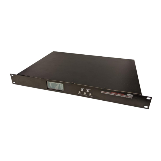
10 Channel Distribution Amplifier w/SNMP
All information provide herein is the property of Novus Power Products LLC The
information included may be reproduced without the permission of Novus Power
Products LLC for the purpose of operating the equipment.
Page #:
1 of 39
USERS MANUAL
REVISION
DATE
ND2310D
www.novuspower.com
ND2310D
A
1/12/20
Advertisement
Chapters
Table of Contents

Related Manuals for Novus NS2310D-R


Summary of Contents for Novus NS2310D-R
- Page 1 1/12/20 ND2310D 10 Channel Distribution Amplifier w/SNMP All information provide herein is the property of Novus Power Products LLC The information included may be reproduced without the permission of Novus Power Products LLC for the purpose of operating the equipment.
-
Page 2: Table Of Contents
USERS MANUAL ND2310D REVISION DATE 1/12/20 Contents 1.0 Summary ......................3 2.0 Controls and Indicators – Front Panel ............. 5 2.1 Channel Status .................... 6 2.2 Status LEDs ....................7 2.3 Input Status ....................7 2.4 Power Supply Status ................... 8 2.6 Alert Threshold .................... - Page 3 USERS MANUAL ND2310D REVISION DATE 1/12/20 1.0 Summary The ND2310D is a ten channel wide bandwidth distribution amplifier. While primarily used for 10 MHz reference distribution, it has a functional bandwidth from DC to 12 MHz but is filtered for the lowest phase noise 10MHz signal.
- Page 4 USERS MANUAL ND2310D REVISION DATE 1/12/20 The amplifier can also be optionally redundantly powered. The redundancy feature adds a second power supply which may be AC or DC. The dual input design monitors the input signals and selects the active signal or the prioritized signal.
-
Page 5: Controls And Indicators - Front Panel
USERS MANUAL ND2310D REVISION DATE 1/12/20 2.0 Controls and Indicators – Front Panel This section describes the functionality of the front panel controls and indicators. Two buttons above the status LEDs provide navigation through the menus. In general, the NEXT button advances through the menus to the next screen, while the SELECT button chooses between the available values on a menu. -
Page 6: Channel Status
USERS MANUAL ND2310D REVISION DATE 1/12/20 2.1 Channel Status The channel status can be determined by reading the actual RMS value on the output of each stage. This is compared to a threshold limit that is set by the user as a percentage variation from a saved value. The default variation value is set at ±25% percent from the current state of the amplifier and is user-programmable in 5% increments from ±10% to ±60%. -
Page 7: Status Leds
USERS MANUAL ND2310D REVISION DATE 1/12/20 2.2 Status LEDs There are three status LEDs which provide a quick indication of valid unit operation. Alert LED: The alert LED will illuminate flashing red to indicate an input failure or a power supply failure. The alert LED will not flash red if any valid input signal is present. -
Page 8: Power Supply Status
USERS MANUAL ND2310D REVISION DATE 1/12/20 2.4 Power Supply Status The power supply status screen provides DC voltage values of the two available power supply sources. The 90-250V AC input is internally connected to an internal 24V AC-DC convertor which powers the internal supplies with 24V. -
Page 9: Alert Threshold
USERS MANUAL ND2310D REVISION DATE 1/12/20 Redundant power supplies operate on either the AC input or DC input, and function independently. All functionality and reporting for an individual power supply and amplifier is independent of its redundant copy. 2.6 Alert Threshold The alert threshold screen allows the user to adjust the tolerance from the reference voltage which, if exceeded in either direction, the output channels will report a fault status. - Page 10 USERS MANUAL ND2310D REVISION DATE 1/12/20 Each channel has a reference voltage which can be set, all at once, by latching the channel’s current value in the latch channel average screen. Each channel’s reference voltage can be set individually by writing the value serially with the $SET command.
- Page 11 USERS MANUAL ND2310D REVISION DATE 1/12/20 The alert threshold can be optimized so that a channel short or an impedance change will cause an alert. Page #: 11 of 39 www.novuspower.com...
- Page 12 USERS MANUAL ND2310D REVISION DATE 1/12/20 Example: The output of channel 1 is connected to a high impedance input and reports 1.25Vrms at the output. The output of channel 2 is connected to a 50 Ohm terminated input, and reports 0.90Vrms at the output. Input A is connected to a ~0.95V 10MHz source.
-
Page 13: Input Threshold
USERS MANUAL ND2310D REVISION DATE 1/12/20 2.7 Input Threshold The input threshold screen allows the user to monitor and set the threshold at which the input is regarded as invalid or faulted. The input threshold value is the absolute voltage (user programmable between 0.1Vrms and 1Vrms) below which the input fault will occur, and the auto input select will consider the signal invalid. -
Page 14: Input Select
USERS MANUAL ND2310D REVISION DATE 1/12/20 2.8 Input Select The input select screen allows the user to monitor and select the input priority for inputs A and B. Pressing the SELECT button with advance through the following settings: Input A Select Input B Select Auto Select (Priority A) Auto Select (Priority B) -
Page 15: Latch Channel Values
USERS MANUAL ND2310D REVISION DATE 1/12/20 2.9 Latch Channel Values The latch channel values screen allows the user to save the current channel output values for use as the reference value for alert settings. A channel alert is triggered when a channel output voltage exceeds or falls below a percentage of the reference value. -
Page 16: Fault Status
USERS MANUAL ND2310D REVISION DATE 1/12/20 2.10 Fault Status The fault status screen allows a quick overview of any channel faults from the front panel. The total fault count is listed, as well as a visual flashing indication of any channels that are beyond the threshold values. Press SELECT to advance to the system fault screen. -
Page 17: Power Switch
USERS MANUAL ND2310D REVISION DATE 1/12/20 2.11 Power Switch The rear panel power switch controls AC power input to the unit. If the optional DC input is provided with 24V, or a valid DC supply, the unit will operate. If the unit is powered with the DC Option, the rear panel switch does not remove DC power. -
Page 18: Rs232 Db9 Port
USERS MANUAL ND2310D REVISION DATE 1/12/20 2.12 RS232 DB9 Port The front panel RS232 port allows convenient setup of the unit in addition to the rear panel RS232 which may be connected to a more permanent instrumentation setup. The front panel RS232 port will respond to the same commands as the rear panel, and any changes made will be reported on both serial ports. -
Page 19: Rear Panel
USERS MANUAL ND2310D REVISION DATE 1/12/20 3.0 Rear Panel 3.1 Channel Outputs - BNC There are ten outputs across the left hand side of the rear panel. They are labeled 1 through 10. Nominally the outputs are 50 Ohm impedance. 3.2 Status LEDs There is an LED to the right of each BNC. -
Page 20: Signal Input A/B
USERS MANUAL ND2310D REVISION DATE 1/12/20 3.3 Signal Input A/B Signal input. Standard impedance is 50 ohms. Maximum signal input is 1.5 Vrms. By default, Auto(A) priority is selected, meaning Signal A is considered primary, and B is used if A is detected as being out of tolerance. -
Page 21: Ac Input
USERS MANUAL ND2310D REVISION DATE 1/12/20 3.5 AC Input The AC input accepts 90-250Vac, 50-60Hz. IEC 320-C14 Compliant. 3.6 RS232 DB-9 An RS232 port is provided for local setup, and status monitoring. The embedded processor provides status strings, as well as command responses. -
Page 22: Functional Description
USERS MANUAL ND2310D REVISION DATE 1/12/20 4.0 Functional Description Page #: 22 of 39 www.novuspower.com... -
Page 23: Bandwidth
USERS MANUAL ND2310D REVISION DATE 1/12/20 4.1 Bandwidth 20 KHz to 10MHz. Gain flatness is ±2dB. The amplifier is available with output drive to DC. Though the unit operates well across wide bandwidth, filtering and design have been optimized to reduce phase noise at 10 MHz. -
Page 24: Outputs
USERS MANUAL ND2310D REVISION DATE 1/12/20 4.3 Outputs Each output is fault and electrostatic discharge protected. Each output is independent, and any output can be faulted for an indefinite period of time with no permanent damage. Each output is connected to a monitor circuit that detects a local fault on the output. -
Page 25: Programming Guide (Rs232 Port: Front And Rear)
USERS MANUAL ND2310D REVISION DATE 1/12/20 Also, in most applications, the equipment that surrounds this unit is sensitive and the filter also reduces noise that could impact the performance of other equipment. If the optional DC Power Option is installed, the unit can be powered from nominal 24 Vdc. - Page 26 USERS MANUAL ND2310D REVISION DATE 1/12/20 The checksum can be required for all input commands, and the requirement for a checksum can be enabled or disabled (default setting is disabled). The checksum method is the two- hexadecimal character representation of an XOR of all characters in the sentence between, but not including, the $ and the * character.
-
Page 27: Rs232 Commands
USERS MANUAL ND2310D REVISION DATE 1/12/20 5.1 RS232 Commands Command Setting Response Description Query Baud Rate on rear panel RS232. (Default = $BAUDNV 115200). Front Panel is 115200 baud. RS232 REAR Assign Baud rate to Rear Panel RS232 port. Default PANEL BAUD $BAUDNV=<current Baud Rate>... - Page 28 USERS MANUAL ND2310D REVISION DATE 1/12/20 Setting Command Response Description $SET<nn>=n.nn Set or query the Reference Voltage for a perticular channel with respect to the active input. Use in combination with the Channel Fault Threshold Factor to define Alert on an individual Channel. Reference Voltages are set with respect to the $SET01=1.00 SET INDIVIDUAL...
- Page 29 USERS MANUAL ND2310D REVISION DATE 1/12/20 Setting Command Response Description $CAL<n>=nn.nn Query or set Cal Factors for specific ADC conversions. See list of Cal Factors numbered for CAL FACTORS $CAL<n>=nn.nn appropriate measurement parameters. These $CAL1=11.10 settings should only be changed by an authorized technician.
-
Page 30: Status String ($Gpnvs,1) Channel Measurements
USERS MANUAL ND2310D REVISION DATE 1/12/20 5.2 Status String ($GPNVS,1) Channel Measurements $GPNVS 1 n.nn n.nn n.nn n.nn n.nn n.nn n.nn n.nn n.nn n.nn * # Description Range 1. Identifier $GPNVS 2. String ID 0.00 – 3.30 [V] 3. Channel 1 Vrms 0.00 –... -
Page 31: Status String ($Gpnvs,2) Power Supply Measurements
USERS MANUAL ND2310D REVISION DATE 1/12/20 5.3 Status String ($GPNVS,2) Power Supply Measurements $GPNVS 2 n.nn n.nn n.nn n.nn n.nn n.nn n.nn ±nnC # Description Range 1. Identifier $GPNVS 2. String ID 3. 24V AC/DC Internal 0.00 to 36.0 [V] 4. -
Page 32: Status String ($Gpnvs,3) Status Bytes
USERS MANUAL ND2310D REVISION DATE 1/12/20 5.4 Status String ($GPNVS,3) Status Bytes $GPNVS 3 0 A 0 0x0000 0x00 0x00 0x00 0x0000 0x0000 0x0000 2 3 4 # Description Range 1. Identifier $GPNVS 2. String ID 3. Active PCB Assembly 0 or 1 4. -
Page 33: Status Byte Key
USERS MANUAL ND2310D REVISION DATE 1/12/20 5.5 Status Byte Key Hex Value (OR'd) Channel ID Channel Status Word 0x1<<0 Channel 1 Fault 0x1<<1 Channel 2 Fault 0x1<<2 Channel 3 Fault 0x1<<3 Channel 4 Fault 0x1<<4 Channel 5 Fault 0x1<<5 Channel 6 Fault 0x1<<6 Channel 7 Fault Channel Status Byte... - Page 34 USERS MANUAL ND2310D REVISION DATE 1/12/20 Hex Value (OR'd) Channel ID Primary PCB Amp Status 0x1<<0 Channel 1 Fault 0x1<<1 Channel 2 Fault 0x1<<2 Channel 3 Fault Internal Fault Primary 0x1<<3 Channel 4 Fault Assembly: The channel 0x1<<4 Channel 5 Fault has failed an internal 0x1<<5 Channel 6 Fault...
- Page 35 USERS MANUAL ND2310D REVISION DATE 1/12/20 Hex Value (OR'd) Status Message 0x1<<0 8V(-) PS out of range 0x1<<1 Reserved Primary and 0x1<<2 Reserved Secondary 0x1<<3 8V(+) PS out of range Power Supply 0x1<<4 5V PS out of range Status 0x1<<5 Communication Failure 0x1<<6 DC Power not present...
-
Page 36: Calibration Factors
USERS MANUAL ND2310D REVISION DATE 1/12/20 5.6 Calibration Factors Calibration Default Description Value CAL00 24Vdc Input Adjust 11.30 CAL01 AC/DC 24V Adjust 11.10 CAL02 Input A Vrms Adjust 2.85 CAL03 Input B Vrms Adjust 2.72 CAL04 Reserved 0.00 CAL05 Reserved 0.00 CAL06 Channel 0-16 Output Vrms Adjust (Primary Board) -
Page 37: Technical Specifications
USERS MANUAL ND2310D REVISION DATE 1/12/20 6.0 Specifications 6.1 Technical Specifications Linear amplifier bandwidth 20KHz to 15MHz ±2db, 1.5 Vrms max (option to DC available) Bandwidth limited for 10 MHz reference applications. Impedance 50 Ohm channel status, system status - front panel display – serial port Channel status, system Rear panel connectors 10 output, signal in and system status BNC... -
Page 38: Limited Hardware Warranty
1 (one) year to be free from defects caused by faulty materials or poor workmanship, provided: (a) NOVUS is notified in writing by Buyer of such defect prior to the expiration of the warranty period, and (b) after receiving return material authorization (RMA) from NOVUS, the defective item is returned with transportation prepaid to NOVUS, Independence, Missouri, with transportation charges prepaid by Buyer …see RMA policy in Terms and Conditions, and... - Page 39 OF SUCH CLAIMS OR DAMAGES. LIMITATION OF REMEDIES: REGARDLESS OF WHETHER ANY REMEDY SET FORTH HEREIN FAILS OF ITS ESSENTIAL PURPOSE, IN NO EVENT WILL NOVUS BE LIABLE TO YOU FOR ANY SPECIAL, CONSEQUENTIAL, INDIRECT OR SIMILAR DAMAGES, INCLUDING, WITHOUT LIMITATION, DAMAGES...
- Page 40 3/24/2020 Appendix D SNMP Configuration All information provided herein is the property of Novus Power Products LLC. The information included may be reproduced without the permission of Novus Power Products LLC for the purpose of operating the equipment. Page #: 1 of 11 www.novuspower.com...
- Page 41 USERS MANUAL SNMP REVISION DATE 3/24/2020 Contents 1.0 SNMP Network Configuration ..................3 1.1 Default Settings ......................3 1.2 Login - Ethernet ......................3 1.3 Login - Serial RS232 (Rear Panel) ................4 1.4 Default Login ......................5 1.5 Navigation ......................... 5 1.6 Static/Dynamic setting IP Address ................
-
Page 42: Snmp Network Configuration
Novus products configured with SNMP option will act as an SNMP agent, providing detailed status and health information about the unit. 1.1 Default Settings By default, the IP address of the Novus product is statically assigned. The default settings are: Field... -
Page 43: Login - Serial Rs232 (Rear Panel)
USERS MANUAL SNMP REVISION DATE 3/24/2020 1.3 Login - Serial RS232 (Rear Panel) To connect to the rear panel RS232 port, you will need a serial cable with pinout that is shown below. The unit has an RS232 debug port for UART 0 of the embedded Linux server. This RS232 level port defaults as the console stdin/stdout and can be accessed by your preferred terminal program such as PuTTY, using a Serial Com port. -
Page 44: Default Login
USERS MANUAL SNMP REVISION DATE 3/24/2020 1.4 Default Login Login using the default login and password: Login Password root novus123 login as: root root@xxx.xxx.xxx.xxx’s password: novus123 1.5 Navigation Once logged in, the “clicommander” is started automatically. The available menu choices are displayed: Top Menu 1. -
Page 45: Static/Dynamic Setting Ip Address
USERS MANUAL SNMP REVISION DATE 3/24/2020 1.6 Static/Dynamic setting IP Address To change the network settings, choose Option 3 from the top menu, and press enter. The following choices are displayed: Network Menu 1. Network IP [Static] Dynamic 3. Network ETH IP Address [192.168.1.200] 4. -
Page 46: Change Password
! " # % & ' ( ) ; < = > ? [ \ ] * + , - . / : ^ _ { | } ~ 1.8 SNMP Agent The Novus unit features an onboard Linux Pi board operating as an SNMPv2 agent. The SNMP data is broadcast from the unit on Port 161. SNMP traps are communicated on Port 162. -
Page 47: Snmp: $Gpnvs Nmea Data
USERS MANUAL SNMP REVISION DATE 3/24/2020 1.10 SNMP: $GPNVS NMEA Data A selection of the $GPNVS field values are used to populate the SNMP OIDs. This allows much of the direct monitoring of the serial RS232 port to be done via the SNMP browser. - Page 48 USERS MANUAL SNMP REVISION DATE 3/24/2020 $GPNVS $GPNVS String SNMP String Field Data Type nsPS1Status.0 OctetString nsPS2Status.0 OctetString nsPS3Status.0 OctetString nsPS4Status.0 OctetString nsPS5Status.0 OctetString nsPS6Status.0 OctetString nsPS7Status.0 OctetString nsPS8Status.0 OctetString nsBITStatus.0 Integer nsPSTemp.0 OctetString nsSensorPotentiometer.0 Gauge nsSensorFanPWM.0 Gauge nsSensorTemperature.0 OctetString nsSysIdentifier.0 OctetString nsSysActivePCBAssy.0...
- Page 49 USERS MANUAL SNMP REVISION DATE 3/24/2020 $GPNVS $GPNVS String SNMP String Field Data Type nsSysGPSLock.0 Integer nsSysSatView.0 Gauge nsSysErrorByte.0 OctetString nsSysFreqDiff.0 OctetString nsSysPPSDiff.0 OctetString nsSysFreqCorSlice.0 OctetString nsSysDACValue.0 Gauge nsSysPS1VDC.0 OctetString nsSysPS2VDC.0 OctetString nsEventDiscCounter.0 Integer nsEventUserEnabled.0 Integer nsEventSysEnabled.0 Integer nsEventGPSLock.0 Integer nsEventRAMIndex.0 Gauge nsEventTimeAlignment.0...
-
Page 50: Serial Commands Via Snmp
USERS MANUAL SNMP REVISION DATE 3/24/2020 1.11 Serial Commands via SNMP The SNMP configuration allows the same RS232 serial commands from the Programmer’s Guide to be sent over the SNMP browser interface. To send a serial command, issue an SNMP set on the “nsCommand” OID. Change the value of the OctetString to the desired serial command.
Need help?
Do you have a question about the NS2310D-R and is the answer not in the manual?
Questions and answers