Table of Contents
Advertisement
Quick Links
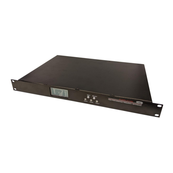
10 Channel Distribution Amplifier
Available Options:
• Ethernet Monitoring
• DC Input
• Square Wave
• PPS
• SNMP
• CAN Bus (for use with Novus redundant systems)
All information provided herein is the property of Novus Power Products LLC.
The information included may be reproduced without the permission of Novus
Power Products LLC for the purpose of operating the equipment.
Page #:
1 of 38
USERS MANUAL
REVISION
DATE
ND2310D
www.novuspower.com
ND2310D
C
071221
Advertisement
Table of Contents

Related Manuals for Novus ND2310D


Summary of Contents for Novus ND2310D
- Page 1 • SNMP • CAN Bus (for use with Novus redundant systems) All information provided herein is the property of Novus Power Products LLC. The information included may be reproduced without the permission of Novus Power Products LLC for the purpose of operating the equipment.
-
Page 2: Table Of Contents
Fault Status ........................19 Power Switch ......................... 20 Distribution Amplifier Cabling - Synchronizing NR2310D-O/G and ND2310D .... 20 Distribution Amplifier Cabling - Synchronizing Two NR2110D-O/G and ND2310D: ... 22 RS232 DB9 Port ......................23 Rear Panel .......................... 24 Channel Outputs – BNC or SMA .................. 24 Signal Input A/B ...................... -
Page 3: Safety
USERS MANUAL ND2310D REVISION DATE 071221 Safety This product has been designed and manufactured to recognized safety standards and rules. The product is a sophisticated electronic instrument that should be installed and operated by highly trained professionals. Installation of this equipment should comply with all local electrical codes. -
Page 4: Mounting
For applications where there is significant shock and vibration, Novus offers equipment with interior mechanical design features to minimize the effects of vibration and shock on the equipment performance. -
Page 5: Summary
071221 Summary The ND2310D is a ten channel wide-bandwidth distribution amplifier. While primarily used for 10 MHz reference distribution, it has a functional bandwidth from DC to 12 MHz but is filtered for the lowest phase noise at 10MHz. For applications other than 10 MHz the unit must be factory configured. - Page 6 USERS MANUAL ND2310D REVISION DATE 071221 The amplifier can also be optionally redundantly powered. The redundancy feature adds a second power supply which may be AC or DC. The dual input design monitors the input signals and selects the active signal or the prioritized signal.
-
Page 7: Controls And Indicators - Front Panel
USERS MANUAL ND2310D REVISION DATE 071221 Controls and Indicators – Front Panel This section describes the functionality of the front panel controls and indicators. Two buttons above the status LEDs provide navigation through the menus. In general, the NEXT button advances through the menus to the next screen, while the SELECT button chooses between the available values on a menu. -
Page 8: Channel Status
USERS MANUAL ND2310D REVISION DATE 071221 Channel Status The channel status can be determined by reading the actual RMS value on the output of each stage. This is compared to a threshold limit that is set by the user as a percentage variation from a saved value. The default variation value is set at ±25% percent from the current state of the amplifier and is user-programmable in... -
Page 9: Status Leds
1000 Ohms. For details on the status strings, see section 5.0 Programmer’s Guide. When using a Novus frequency reference, there is a separate (optional) CAN bus between the unit and the references. The CAN bus communicates to the... -
Page 10: Power Supply Status
USERS MANUAL ND2310D REVISION DATE 071221 distribution amplifier and the references, a complete status of the reference. Information regarding internal BIT, lock, frequency error are all communicated to make an A/B selection while in the Auto mode. In the manual mode, the distribution amplifier will remain connected to the manually selected A or B regardless of the source status. -
Page 11: Amplitude Alert Threshold
USERS MANUAL ND2310D REVISION DATE 071221 Redundant power supplies operate on either the AC input or DC input, and function independently. All functionality and reporting for an individual power supply and amplifier is independent of its redundant copy. Amplitude Alert Threshold... - Page 12 USERS MANUAL ND2310D REVISION DATE 071221 Each channel has a reference voltage which can be set, all at once, by latching the channel’s current value in the latch channel average screen. Each channel’s reference voltage can be set individually by writing the value serially with the $SET command.
- Page 13 USERS MANUAL ND2310D REVISION DATE 071221 The alert threshold can be optimized so that a channel short or an impedance change will cause an alert. Example: Page #: 13 of 38 www.novuspower.com...
- Page 14 USERS MANUAL ND2310D REVISION DATE 071221 The output of Channel 1 is connected to a high impedance input and reports 1.25Vrms at the output. The output of Channel 2 is connected to a 50 Ohm terminated input and reports 0.90Vrms at the output.
-
Page 15: Input Threshold
USERS MANUAL ND2310D REVISION DATE 071221 Input Threshold The input threshold screen allows the user to monitor and set the threshold at which the input is regarded as invalid or faulted. The input threshold value is the absolute voltage (user-programmable between 0.1Vrms and 1Vrms) below which the input fault will occur, and the auto input... -
Page 16: Input Select (When Used With Novus Select References)
REVISION DATE 071221 Input Select (when used with Novus select references) The input select screen allows the user to monitor and select the input priority for inputs A and B. Pressing the SELECT button with advance through the following settings:... - Page 17 USERS MANUAL ND2310D REVISION DATE 071221 Switch input on loss of GNSS lock To select Priority Input on Lock (must have CAN connection to NR2110): o $PRLK=1 via serial port o $INP=2 or $INP=3 If the input source indicates loss of GNSS lock, the ND2310 will select the backup signal if the backup unit reports GNSS lock is valid.
-
Page 18: Latch Channel Values
USERS MANUAL ND2310D REVISION DATE 071221 Latch Channel Values The latch channel values screen allows the user to save the current channel output values for use as the reference value for alert settings. A channel alert is triggered when a channel output voltage exceeds or falls below a percentage of the reference value. -
Page 19: Fault Status
USERS MANUAL ND2310D REVISION DATE 071221 Fault Status The fault status screen allows a quick overview of any channel faults from the front panel. The total fault count is listed, as well as a visual flashing indication of any channels that are beyond the threshold values. -
Page 20: Power Switch
1. Install the NR2310D-O/G in a 19” rack. Be sure to secure the unit with appropriate fasteners to the rack. 2. Install the ND2310D above or below the NR2310D and again secure with appropriate fasteners. Be sure the cable can reach between the units. - Page 21 USERS MANUAL ND2310D REVISION DATE 071221 NR2310D ND2310D 4. Attach the free end of the cable on #1 10 MHz to the Input A port one the ND2310D. NR2310D ND2310D 6. Carefully tighten the SMA connector with a 5/16” wrench until 8 in-lbs.
-
Page 22: Distribution Amplifier Cabling - Synchronizing Two Nr2110D-O/G And Nd2310D
The Novus ten channel distribution amplifier will accept two sources. In this case, the two sources will be the Novus NR2110D-O/G single channel GNSS locked frequency references. -
Page 23: Rs232 Db9 Port
USERS MANUAL ND2310D REVISION DATE 071221 RS232 DB9 Port The front panel RS232 port allows convenient setup of the unit in addition to the rear panel RS232 which may be connected to a more permanent instrumentation setup. The front panel RS232 port will respond to the same commands as the rear panel, and any changes made will be reported on both serial ports. -
Page 24: Rear Panel
USERS MANUAL ND2310D REVISION DATE 071221 Rear Panel Channel Outputs – BNC or SMA There are ten outputs across the left-hand side of the rear panel. They are labeled 1 through 10. Nominally, the outputs are 50 Ohm impedance. Signal Input A/B Standard impedance is 50 Ohms. -
Page 25: Dc Input
USERS MANUAL ND2310D REVISION DATE 071221 DC Input The DC input connector is a - pin Amphenol circular connector, P/N DL3102A10SL-3P. The mating connector is available as P/N DL3106A10SL-3S. The default DC input voltage is 24Vdc. Custom voltage ranges can be provided from -60Vdc to +60Vdc. -
Page 26: Can Connector (Optional)
CAN Connector (optional) The ND2310D has an optional CAN bus connection for interrogation of external input source reference NR2x10. The bus provides proprietary status signaling to ensure input status is known, including BIT, GNSS lock, holdover status and health of the input source. - Page 27 USERS MANUAL ND2310D REVISION DATE 071221 Function CAN_L CAN_GND CAN_H Page #: 27 of 38 www.novuspower.com...
-
Page 28: Functional Description
USERS MANUAL ND2310D REVISION DATE 071221 Functional Description Page #: 28 of 38 www.novuspower.com... -
Page 29: Bandwidth
USERS MANUAL ND2310D REVISION DATE 071221 Bandwidth 20 KHz to 10MHz. Gain flatness is ±2dB. The amplifier is available with output drive to DC. Though the unit operates well across wide bandwidth, filtering and design have been optimized to reduce phase noise at 10 MHz. -
Page 30: Outputs
USERS MANUAL ND2310D REVISION DATE 071221 Outputs Each output is fault and electrostatic discharge protected. Each output is independent, and any output can be faulted for an indefinite period of time with no permanent damage. Each output is connected to a monitor circuit that detects a local fault on the output. -
Page 31: Programming Guide (Rs232 Port: Front And Rear)
DATE 071221 Programming Guide (RS232 Port: Front and Rear) The ND2310D can accept user commands which will provide specific fault detection performance which may be customized by the user. The settings can be saved in non-volatile flash memory. If the user makes one or more changes which are intended to be kept between power-off cycles, the command “$SAVEFLASH*51 <CR><LF>”... -
Page 32: Rs232 Commands
Vpp is lower than 0.3V. $PRLK prioritizes input based on GNSS and Loop Lock $PRLK status of input source (CAN connected Novus NR PRIORITIZE INPUT reference). When $PRLK is active, the input will ON LOCK STATUS $PRLK=<current PRLK>... - Page 33 USERS MANUAL ND2310D REVISION DATE 071221 Setting Command Response Description $CAL<n>=nn.nn Query or set Cal Factors for specific ADC conversions. See list of Cal Factors numbered for CAL FACTORS $CAL<n>=nn.nn appropriate measurement parameters. These $CAL1=11.10 settings should only be changed by an authorized technician.
-
Page 34: Status String ($Gpnvs) Channel Measurements
USERS MANUAL ND2310D REVISION DATE 071221 Status String ($GPNVS) Channel Measurements See Appendix C: $GPNVS Status String Definitions SNMP Reference See Appendix D SNMP Reference Page #: 34 of 38 www.novuspower.com... -
Page 35: Specifications
USERS MANUAL ND2310D REVISION DATE 071221 Specifications Technical Specifications Linear amplifier bandwidth 20KHz to 15MHz ±2db, 1.2 Vrms max (option to DC available) Bandwidth limited for 10 MHz reference applications. Impedance 50 Ohm Channel skewing < 1 ns (typical < 200 ps). -
Page 36: Environmental And Mechanical
USERS MANUAL ND2310D REVISION DATE 071221 Environmental and Mechanical Operating temperature 0 to 50°C non-condensing Storage temperature -40 to 70°C Height 1RU (~1.73”) Width 19.0” Depth 12.0” Weight 5.5 lbs. AC input 90 to 250 Vac, 50/60Hz, less than 10 Watts... -
Page 37: Limited Hardware Warranty
1 (one) year to be free from defects caused by faulty materials or poor workmanship, provided: (a) NOVUS is notified in writing by Buyer of such defect prior to the expiration of the warranty period, and (b) after receiving return material authorization (RMA) from NOVUS, the defective item is returned with transportation prepaid to NOVUS, Independence, Missouri, with transportation charges prepaid by Buyer …see RMA policy in Terms and Conditions, and... - Page 38 071221 LIMITATION OF REMEDIES: REGARDLESS OF WHETHER ANY REMEDY SET FORTH HEREIN FAILS OF ITS ESSENTIAL PURPOSE, IN NO EVENT WILL NOVUS BE LIABLE TO YOU FOR ANY SPECIAL, CONSEQUENTIAL, INDIRECT OR SIMILAR DAMAGES, INCLUDING, WITHOUT LIMITATION, DAMAGES FOR LOSS OF BUSINESS PROFITS, BUSINESS INTERRUPTION, LOSS OF DATA OR BUSINESS...
- Page 39 $GPNVS Appendix C: $GPNVS Status String Definitions All information provide herein is the proprietary property of Novus Power Products L.L.C. The information included may be reproduced without the permission of Novus Power Products L.L.C. with out prior approval for purpose of operating the equipment.
- Page 40 Users manual $GPNVS Revision #: Date: 8/25/20 Contents 1.0 The $GPNVS Serial Status String ................3 1.1 Status String ($GPNVS,1) Fault Bytes ..............4 1.2 Status String ($GPNVS,2) Channel Values 1-8 ............5 1.3 Status String ($GPNVS,3) Power Supply Values............. 6 1.4 Status String ($GPNVS,4) Channel Values 9-16 .............
-
Page 41: The $Gpnvs Serial Status String
Date: 8/25/20 1.0 The $GPNVS Serial Status String Novus products provide, in many cases, serial data output from a standard GNSS receiver matching the NMEA 0183 protocol. This is usually a direct connection to the receiver. In addition to NMEA, Novus Products which provide an additional RS232 serial port for status monitoring, will be set up to meet the following protocols. -
Page 42: Status String ($Gpnvs,1) Fault Bytes
Users manual $GPNVS Revision #: Date: 8/25/20 1.1 Status String ($GPNVS,1) Fault Bytes $GPNVS 1 hhmmss mmddyy A A nn nn 0x0000 0x00 0x00 * XX 12 13 # Description Range 1. Identifier $GPNVS 2. String ID 3. Time (UTC) hhmmss 4. - Page 43 Users manual $GPNVS Revision #: Date: 8/25/20 1.2 Status String ($GPNVS,2) Channel Values 1-8 $GPNVS 2 hhmmss ddmmyy n.nn n.nn n.nn n.nn n.nn n.nn n.nn n.nn * XX # Description Range 1. Identifier $GPNVS 2. String ID 3. Time (UTC) hhmmss 4.
-
Page 44: Status String ($Gpnvs,3) Power Supply Values
Users manual $GPNVS Revision #: Date: 8/25/20 1.3 Status String ($GPNVS,3) Power Supply Values $GPNVS 3 hhmmss ddmmyy n.nn n.nn n.nn n.nn n.nn n.nn n.nn n.nn nn * XX 13 14 # Description Range 1. Identifier $GPNVS 2. String ID 3. - Page 45 Users manual $GPNVS Revision #: Date: 8/25/20 1.4 Status String ($GPNVS,4) Channel Values 9-16 $GPNVS 4 hhmmss ddmmyy n.nn n.nn n.nn n.nn n.nn n.nn n.nn n.nn * XX # Description Range 1. Identifier $GPNVS 2. String ID 3. Time (UTC) hhmmss 4.
-
Page 46: Status String ($Gpnvs,5) Sensors
Users manual $GPNVS Revision #: Date: 8/25/20 1.5 Status String ($GPNVS,5) Sensors $GPNVS 5 hhmmss ddmmyy nnn ±nn * XX # Description Range 1. Identifier $GPNVS 2. String ID 3. Time (UTC) hhmmss 4. Date mmddyy 5. Potentiometer Hex Value 000 to FFF 6. -
Page 47: Status String ($Gpnvs,6) Status Bytes
Users manual $GPNVS Revision #: Date: 8/25/20 1.6 Status String ($GPNVS,6) Status Bytes There are two different Status Strings; one for everything except the NR2304 and one for the NR2304. 1.6.1 Status String ($GPNVS,6) Status Bytes; Standard $GPNVS 6 0 A 0 0x0000 0x00 0x00 0x00... -
Page 48: Status String ($Gpnvs,6) Status Bytes; Rubidium
Users manual $GPNVS Revision #: Date: 8/25/20 1.6.2 Status String ($GPNVS,6) Status Bytes; Rubidium $GPNVS nnn 0x0000 nnn # Description Range 1. Identifier $GPNVS 2. String ID 3. Heat Sink Temperature 0-255 4. Heater Current Voltage 0x0000-0x0136 5. Measured Voltage in Heater 0-255 6. -
Page 49: Status String ($Gpnvs,7) Status Bytes
Users manual $GPNVS Revision #: Date: 8/25/20 1.7 Status String ($GPNVS,7) Status Bytes $GPNVS 7 nnnnnn nnnnnn A nn 0x00 nnnnnn n.nn n.nn # Description Range 1. Identifier $GPNVS 2. String ID 3. Time hhmmss 4. Date mmddyy “A” = Valid, “V” = Not Valid 5. -
Page 50: Event String ($Gpnvs,8) Event Status
Users manual $GPNVS Revision #: Date: 8/25/20 1.8 Event String ($GPNVS,8) Event Status $GPNVS nnnnnn # Description Range 1. Identifier $GPNVS 2. String ID 3. Discipline Counter 0 = Off, 1 = Disciplined to Synthetic PPS 4. User Enabled 0 = Off, 1 = On 5. -
Page 51: Status String ($Gpnvs,9) Frequency Measurement
Users manual $GPNVS Revision #: Date: 8/25/20 1.9 Status String ($GPNVS,9) Frequency Measurement The frequency measurement string has two versions, one standard version, and one for the NR6720. 1.9.1 Standard Frequency Measurement String $GPNVS hhmmss ddmmyy (n)nnnnnnn.nnn (-)nn # Description Range 1. -
Page 52: Nr6720-Hs Frequency Measurement String
Users manual $GPNVS Revision #: Date: 8/25/20 1.9.2 NR6720-HS Frequency Measurement String $GPNVS nnnnnnn.nnn n.nnnnn nnnnnnnn.nn ±n.nn ±n.nn * # Description Range 1. Identifier $GPNVS 2. String ID 3. Frequency (Loop Period) 10000000.000 4. DAC Voltage (Double) 2.00000 5. Frequency (per second) 10000000.0 6. -
Page 53: Pps Alignment String ($Gpnvs,10) Pps Status
Users manual $GPNVS Revision #: Date: 8/25/20 1.10 PPS Alignment String ($GPNVS,10) PPS Status $GPNVS 10 ±n ±n ±n # Description Range 1. Identifier $GPNVS 2. String ID 3. PPS Stability Enabled 0 = Off, 1 = On 4. PPS Disciplining to GPS 0 = Off, 1 = Actively Synchronized 5. -
Page 54: Pps Alignment String ($Gpnvs,9) Pps Status
Users manual $GPNVS Revision #: Date: 8/25/20 1.12 PPS Alignment String ($GPNVS,9) PPS Status $GPNVS nnn 0x0000 nnn # Description Range 8. Identifier $GPNVS 9. String ID 10. Heat Sink Temperature 0-255 11. Heater Current Voltage 0x0000-0x0136 12. Measured Voltage in Heater 0-255 13. -
Page 55: Response String ($Gpnvs,R)
Users manual $GPNVS Revision #: Date: 8/25/20 1.11 Response String ($GPNVS,R) $GPNVS R n <response> * XX # Description Range 1. Identifier $GPNVS 2. Response ID 3. Command Success 1 = Success, 0 = Fail 4. Response <see example responses> *XX (xor’d value of bytes between $ and *) 5. -
Page 56: Discipline Selection String ($Gpnvs,13)
Users manual $GPNVS Revision #: Date: 8/25/20 1.12 Discipline Selection String ($GPNVS,13) $GPNVS, # Description Range 1. Identifier $GPNVS 2. String ID 3. Priority Discipline Source 0 = GNSS, 1 = 10MHz input, 2 = Optical input 4. Current Discipline Source 0 = GNSS, 1 = 10MHz, 2 = Optical, 3 = Holdover 5. -
Page 57: Combined Nmea/Status Rs232
Users manual $GPNVS Revision #: Date: 8/25/20 2.0 Combined NMEA/Status RS232 NR2110-OG Combined NMEA?Status Port 2.1 Status String ($GPNVS,1) Fault Bytes $GPNVS 1 hhmmss mmddyy nn 0x00 0x00 0x00 * XX # Description Range 15. Identifier $GPNVS 16. String ID 17. -
Page 58: Status String ($Gpnvs,2) Channel Values
Users manual $GPNVS Revision #: Date: 8/25/20 2.2 Status String ($GPNVS,2) Channel Values $GPNVS 1 hhmmss mmddyy n.nn n.nn n.nn n.nn n.nn n.nn * XX # Description Range 14. Identifier $GPNVS 15. String ID 16. Time (UTC) hhmmss 17. Date mmddyy 18. -
Page 59: Status String ($Gpnvs,3) Power Supply Values
Users manual $GPNVS Revision #: Date: 8/25/20 2.3 Status String ($GPNVS,3) Power Supply Values $GPNVS 3 hhmmss mmddyy n.nn n.nn n.nn n.nn n.nn # Description Range 15. Identifier $GPNVS 16. String ID 17. Time (UTC) hhmmss 18. Date mmddyy 19. -5Vdc Power Supply(opt) -30.0 to 30.0 [V] 20. -
Page 60: Status Byte Key
Users manual $GPNVS Revision #: Date: 8/25/20 3.0 Status Byte Key Hex Value (OR'd) Channel ID Channel Status Word 0x1<<0 Channel 1 Fault 0x1<<1 Channel 2 Fault 0x1<<2 Channel 3 Fault 0x1<<3 Channel 4 Fault 0x1<<4 Channel 5 Fault 0x1<<5 Channel 6 Fault 0x1<<6 Channel 7 Fault... - Page 61 Users manual $GPNVS Revision #: Date: 8/25/20 Hex Value (OR'd) Channel ID Primary PCB Amp Status 0x1<<0 Channel 1 Fault 0x1<<1 Channel 2 Fault 0x1<<2 Channel 3 Fault Internal Fault Primary 0x1<<3 Channel 4 Fault Assembly: The channel 0x1<<4 Channel 5 Fault has failed an internal 0x1<<5 Channel 6 Fault...
- Page 62 Users manual $GPNVS Revision #: Date: 8/25/20 Hex Value (OR'd) Status Message 0x1<<0 Flash Read Boot Error (Deprecated) 0x1<<1 Potentiometer Read/Set Fail 0x1<<2 Reserved Active Board 0x1<<3 Reserved Status 0x1<<4 PCB Assembly Input A/B Select Fail 0x1<<5 Reserved 0x1<<6 Reserved 0x1<<7 Reserved Hex Value (OR'd)
- Page 63 SNMP Appendix D: SNMP Configuration All information provide herein is the proprietary property of Novus Power Products L.L.C. The information included may be reproduced without the permission of Novus Power Products L.L.C. without prior approval for purpose of operating the equipment.
- Page 64 User’s manual SNMP Revision #: Date: 7/15/21 Contents 1.0 SNMP Network Configuration ..................3 1.1 Default Settings ......................3 1.2 Login - Ethernet ......................6 1.3 Login - Serial RS232 (Rear Panel) ................5 1.4 Default Login ......................6 1.5 Navigation..............Error! Bookmark not defined. 1.6 Static/Dynamic setting IP Address ......
-
Page 65: Snmp Network Configuration
Novus products configured with SNMP option will act as an SNMP agent, providing detailed status and health information about the unit. 1.1 Default Settings By default, the IP address of the Novus product is statically assigned. The default settings are: Field... - Page 66 User’s manual SNMP Revision #: Date: 7/15/21 1.2 Setting Static IP via the RS232 Serial Port The Linux NTP/SNMP submodule static IP address can be updated via the serial port. The user should set and query each of the following in order: Command Description $ETHIP...
- Page 67 User’s manual SNMP Revision #: Date: 7/15/21 1.3 Serial RS232 (Rear Panel) To connect to the rear panel RS232 port. You will need a serial cable with pinout that is shown below. This RS232 level port defaults as the NMEA/Command interface and can be accessed by your preferred terminal program such as PuTTY, using a Serial Com port.
-
Page 68: Login - Ethernet
User’s manual SNMP Revision #: Date: 7/15/21 1.3 Login - Ethernet Use a terminal such as PuTTY to open an SSH connection to IP address of the unit on Port 22. You will see the “login as:” prompt, where you can enter the login and password. -
Page 69: Snmp Agent
The SNMP agent OID values are pulled from the $GPNVS string data and include all the available status output that the $GPNVS strings provide. Not all Novus units provide all $GPNVS strings, or all specific parameters in $GPNVS strings. The fields populated in the OIDs are from the specific unit’s $GPNVS values. -
Page 70: Snmp: $Gpnvs Nmea Data
User’s manual SNMP Revision #: Date: 7/15/21 1.10 SNMP: $GPNVS NMEA Data A selection of the $GPNVS field values are used to populate the SNMP OIDs. This allows much of the direct monitoring of the serial RS232 port to be done via the SNMP browser. - Page 71 User’s manual SNMP Revision #: Date: 7/15/21 $GPNVS $GPNVS String SNMP String Field Data Type nsStatusPSObjs nsPS1Status.0 OctetString nsPS2Status.0 OctetString nsPS3Status.0 OctetString nsPS4Status.0 OctetString nsPS5Status.0 OctetString nsPS6Status.0 OctetString nsPS7Status.0 OctetString nsPS8Status.0 OctetString nsBITStatus.0 Integer nsPSTemp.0 OctetString nsSensorObjs nsSensorPotentiometer.0 Gauge nsSensorFanPWM.0 Gauge nsSensorTemperature.0 OctetString...
- Page 72 User’s manual SNMP Revision #: Date: 7/15/21 $GPNVS $GPNVS String SNMP String Field Data Type nsSysGPSLock.0 Integer nsSysSatView.0 Gauge nsSysErrorByte.0 OctetString nsSysFreqDiff.0 OctetString nsSysPPSDiff.0 OctetString nsSysFreqCorSlice.0 OctetString nsSysDACValue.0 Gauge nsSysPS1VDC.0 OctetString nsSysPS2VDC.0 OctetString nsEventObjs nsEventDiscCounter.0 Integer nsEventUserEnabled.0 Integer nsEventSysEnabled.0 Integer nsEventGPSLock.0 Integer nsEventRAMIndex.0...
-
Page 73: Serial Commands Via Snmp
User’s manual SNMP Revision #: Date: 7/15/21 1.11 Serial Commands via SNMP The SNMP configuration allows the same RS232 serial commands from the Programmer’s Guide to be sent over the SNMP browser interface. To send a serial command, issue an SNMP set on the “nsCommand” OID. Change the value of the OctetString to the desired serial command. -
Page 74: Troubleshooting
User’s manual SNMP Revision #: Date: 7/15/21 1.12 Troubleshooting If changes were made to the network settings that render the unit unable to communicate, please contact customer service for instructions on writing to the SSD card directly. Page #: 12 of 12 www.novuspower.com...
Need help?
Do you have a question about the ND2310D and is the answer not in the manual?
Questions and answers