Table of Contents
Advertisement
Quick Links
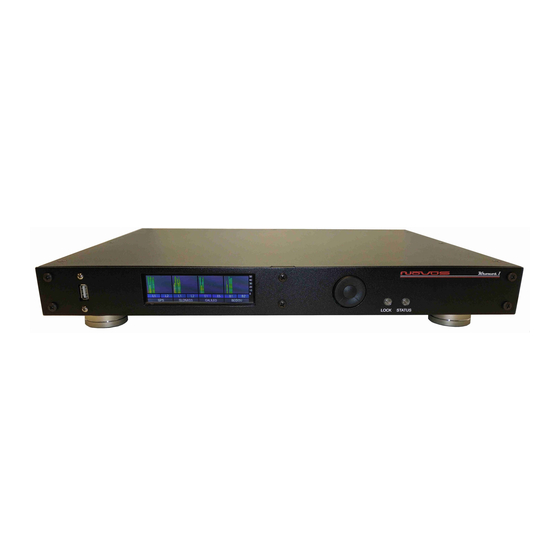
10MHz Rubidium Frequency Reference, High Performance, Low
All information provided herein is the property of Novus Power Products LLC. The information
included may be reproduced without the permission of Novus Power Products LLC. for the
purpose of operating the equipment.
Page 1 of 59
NR9000
Kronos Ι
Noise, GNSS-Locked
USERS
MANUAL
REVISION
DATE
www.novuspower.com
NR9000
Kronos 1
C
2/22/23
Advertisement
Table of Contents

Related Manuals for Novus Kronos Ι


Summary of Contents for Novus Kronos Ι
- Page 1 10MHz Rubidium Frequency Reference, High Performance, Low Noise, GNSS-Locked All information provided herein is the property of Novus Power Products LLC. The information included may be reproduced without the permission of Novus Power Products LLC. for the purpose of operating the equipment.
-
Page 2: Table Of Contents
NR9000 USERS Kronos 1 MANUAL REVISION DATE 2/22/23 of Contents Table Safety ..............................4 Mounting ..............................5 Summary ............................... 6 Thermally Isolated Reference (HS3) ......................9 Controls and Indicators ........................13 Front Panel ............................13 LEDs............................. 13 Navigation Paddle ........................13 Menu Layers ............................ - Page 3 NR9000 USERS Kronos 1 MANUAL REVISION DATE 2/22/23 System Status ..........................37 Power Supply Status ........................37 System Faults ..........................38 Channel Faults ..........................38 Channel Outputs – BNC or SMA ....................39 Antenna Input A/B – SMA ......................39 AC Input ............................
-
Page 4: Safety
NR9000 USERS Kronos 1 MANUAL REVISION DATE 2/22/23 Safety This product has been designed and manufactured to recognized safety standards and rules. This product is a sophisticated electronic instrument that should be installed and operated by highly trained professionals. Installation of this equipment should comply with all local electrical codes. Utilization of this equipment in a manner inconsistent with the operating instructions can be dangerous. -
Page 5: Mounting
For applications where there is significant shock and vibration, Novus offers equipment with interior mechanical design features to minimize the effects of vibration and shock on the equipment performance. -
Page 6: Summary
DATE 2/22/23 Summary Kronos Ι The Novus represents our highest performance reference for the most demanding master reference applications. The 184 channel GNSS receiver provides critical timing information that is highly processed to minimize reference jitter and noise. The receiver supports GPS L1C/A L2C, GLO L1OF L2OF, GAL E1B/C E5b, BDS B1I B2I, QZSS L1C/A L1S L2C, SBAS L1C/A. - Page 7 NR9000 USERS Kronos 1 MANUAL REVISION DATE 2/22/23 Our most advanced designs address long time constants digitally. High performance picosecond measurement techniques provide greater timing resolution. Advanced algorithms coupled with precise analog designs that are thermally controlled, and vibration-isolated allow Allan Deviation performance approaching E-14.
- Page 8 NR9000 USERS Kronos 1 MANUAL REVISION DATE 2/22/23 Our algorithms process the radio information to achieve a more stable reference. The curve below is a plot of timing jitter after processing: The standard deviation improved from 17 ns to approximately 400 picoseconds. The most advanced loop reports calculated Allan Deviation between the filtered PPS and the OCXO output on real time basis locally on a display and/or a selected serial port.
-
Page 9: Thermally Isolated Reference (Hs3)
NR9000 USERS Kronos 1 MANUAL REVISION DATE 2/22/23 Thermally Isolated Reference (HS3) A real time continuous calculation of Allan Deviation is performed and is likely the best indicator of reference health one could have. Data logging allows the user to review timing performance on any day from a performance log that is more than a year deep. - Page 10 NR9000 USERS Kronos 1 MANUAL REVISION DATE 2/22/23 To further enhance stability, the timing control network and reference are vibration and thermally- isolated. The timing loop operates with a 40 ps resolution to enhance process control. Power supplies include wide bandwidth linear regulators to eliminate ripple noise from the amplifiers.
- Page 11 NR9000 USERS Kronos 1 MANUAL REVISION DATE 2/22/23 The unit features extensive reporting via the rear panel RS232 port - equipment status, output voltage on each channel and redundancy status. By being able to monitor the output voltage, the user can detect cabling issues that cause an impedance change and replace cabling before it completely fails.
- Page 12 NR9000 USERS Kronos 1 MANUAL REVISION DATE 2/22/23 There will be one in a non-redundant configuration. Each power supply supplies one of the amplifier assemblies. Page 12 of 59 www.novuspower.com...
-
Page 13: Controls And Indicators
NR9000 USERS Kronos 1 MANUAL REVISION DATE 2/22/23 Controls and Indicators Front Panel This section describes the functionality of the front panel controls and indicators. LEDs Two front panel LEDs provide a quick indication of the Kronos’ status. The LOCK indicator will illuminate solid green if both GNSS receivers have acquired GPS lock, and are actively controlling the respective modules. -
Page 14: Menu Layers
NR9000 USERS Kronos 1 MANUAL REVISION DATE 2/22/23 Menu Layers Page 14 of 59 www.novuspower.com... -
Page 15: Display Navigation
NR9000 USERS Kronos 1 MANUAL REVISION DATE 2/22/23 Display Navigation Time and Date Time and Date Screen The initial Time and Date screen provides an offset adjusted reference to UTC as delivered by the primary GNSS unit. The lock status of both GPS 1 and GPS 2 are also provided as a quick reference check to see that both modules are GNSS locked and are reporting as healthy. -
Page 16: Analog Clock Face
NR9000 USERS Kronos 1 MANUAL REVISION DATE 2/22/23 Analog Clock Face The offset adjusted UTC time is displayed as an analog clock face. To adjust UTC offset (to local time zone), use the navigation paddle to move to the Time Display Preference screen. Time Display Preference The Time Display Preference screen allows the user to choose 12 hour or 24 hour time display. -
Page 17: Gnss Data Display
NR9000 USERS Kronos 1 MANUAL REVISION DATE 2/22/23 GNSS Data Display GNSS data is provided that consists of 3D positioning (Latitude, Longitude, Altitude). The primary GNSS satellite count displays the number of GNSS constellation satellites that are currently being used in the fix calculation. The Kronos maintains two internal GNSS radios. - Page 18 NR9000 USERS Kronos 1 MANUAL REVISION DATE 2/22/23 DONE: The Survey-In process has completed both minimum time and minimum accuracy requirement. The position will now be fixed at the current solution and the unit enters time mode. In addition, two indicators relate the validity of the position fix: OK: This indicates the receiver is reporting a valid Survey-In indicator.
-
Page 19: Gnss Multiband Snr Meter
NR9000 USERS Kronos 1 MANUAL REVISION DATE 2/22/23 GNSS MultiBand SNR Meter The primary GNSS provides Signal-to-Noise ratio in dB as per the NMEA 0183 GSV standard. The ratio is expressed in dB as a representation of the strength of the RF signal above the noise floor. -
Page 20: Survey Mode
NR9000 USERS Kronos 1 MANUAL REVISION DATE 2/22/23 Survey Mode The Survey Mode screen allows the user to choose between fixed position and the initial Survey-In requirement on startup. To use the fixed-position mode, first complete a Survey-In period of 36 hours at the intended antenna location. The GNSS Data Display screen will indicate that the survey in is complete when the “SRV”... -
Page 21: Frequency Data, Reporting, And Monitoring
NR9000 USERS Kronos 1 MANUAL REVISION DATE 2/22/23 Frequency Data, Reporting, and Monitoring The Kronos unit contains a second GNSS locked radio to monitor the output of the GPS locked Rb or OCXO source. This monitor is labeled as GPS 2, and provides a one-second frequency count of the source input. - Page 22 NR9000 USERS Kronos 1 MANUAL REVISION DATE 2/22/23 Allan Deviation To display a representation of Allan Deviation with respect to the GNSS locked pulse-per- second, we use the following method. The difference between the GNSS provided pulse-per-second and the OCXO synthesized pulse-per-second are captured at each period to a precision of ±40 picoseconds.
-
Page 23: Frequency Statistics
NR9000 USERS Kronos 1 MANUAL REVISION DATE 2/22/23 Frequency Statistics Frequency statistics are continuously monitored and saved to non-volatile memory every twenty-four hours. The Frequency Statistics screen displays the current parameters and includes the parameters that are saved to non-volatile memory. The values on this screen are not valid during warmup, nor while achieving GNSS lock. -
Page 24: Save Now Button
NR9000 USERS Kronos 1 MANUAL REVISION DATE 2/22/23 Save Now Button The frequency statistics are saved daily at 00:00:00 UTC. They can also be saved arbitrarily at any time by pressing the “Save Now” button. The current ADEV statistics will be saved to non- volatile memory and can be accessed from the serial port or viewed on the “Frequency Statistics History”... -
Page 25: Frequency Statistics History
NR9000 USERS Kronos 1 MANUAL REVISION DATE 2/22/23 Frequency Statistics History The Frequency Statistics History screen displays the historical values with a Time and Date stamp. With the time and date, a “Position” value is labeled for direct access from the serial port. - Page 26 NR9000 USERS Kronos 1 MANUAL REVISION DATE 2/22/23 Output Channel Status Monitoring The channel status is determined by reading the actual RMS value in volts on the output of each stage. This value is compared to a threshold limit that is set by the user as a percentage variation from a saved value.
-
Page 27: Latch Channel Values
NR9000 USERS Kronos 1 MANUAL REVISION DATE 2/22/23 For example, “Ch 5” indicates the monitored channel output value in Vrms in white. Above and below the channel value, the High and Low thresholds are shown. If the channel output exceeds either the high or low threshold, the output value will illuminate in red, and the STATUS LED will blink red. -
Page 28: Setting Amplitude And Threshold Alert
NR9000 USERS Kronos 1 MANUAL REVISION DATE 2/22/23 Setting Amplitude and Threshold Alert The Amplitude and Threshold screen allows the user to adjust the tolerance from the reference voltage which, if exceeded in either direction, the output channels will report a fault status. The default threshold value is set at ±55% from the current state of the amplifier, and is user- programmable from ±10% to ±60%. -
Page 29: Amplitude Reference Point
NR9000 USERS Kronos 1 MANUAL REVISION DATE 2/22/23 Amplitude Reference Point To change an individual channel’s amplitude reference point: 1. Press the “Amplitude” button on the touchscreen. 2. Press the input for which this channel reference relates. For reference applications, use A only a. - Page 30 NR9000 USERS Kronos 1 MANUAL REVISION DATE 2/22/23 b. “BkSp” will delete the last character. “Clear” will clear the number entry completely. 4. The Threshold indicator will be updated to display the new value. After saving the current configuration on a channel, any subsequent deviation on that channel which exceeds the alert threshold percentage will trigger an alert.
- Page 31 NR9000 USERS Kronos 1 MANUAL REVISION DATE 2/22/23 The alert threshold can be optimized so that a channel short or an impedance change will cause an Alert. Page 31 of 59 www.novuspower.com...
- Page 32 NR9000 USERS Kronos 1 MANUAL REVISION DATE 2/22/23 Example: The output of channel 1 is connected to a high impedance input and reports 1.25Vrms at the output. The output of channel 2 is connected to a 50ohm terminated input and reports 0.90Vrms at the output.
-
Page 33: Rubidium Module Status
NR9000 USERS Kronos 1 MANUAL REVISION DATE 2/22/23 Rubidium Module Status The Rubidium screen provides several key indicators for Rb module health. Under normal conditions, the Rubidium module will progress through Heating/Initialization and Laser Lock within minutes and the unit will be fully locked within thirty minutes. The fully locked Rb module will, without further discipline, use the best-known coefficients and provide a stable source for the OCXO to discipline. - Page 34 NR9000 USERS Kronos 1 MANUAL REVISION DATE 2/22/23 Rubidium Status Field Reading Description Heat/Init Initialization and Warmup Laser Lock Initial State, Frequency not yet valid Status Locked System Lock Error Rb is reporting, but an error exists No alarm uWave Lost Indicates that the microwave signal is lost Temp Alarm Indicates the laser cavity temperature alarm...
-
Page 35: Ocxo Module Status
NR9000 USERS Kronos 1 MANUAL REVISION DATE 2/22/23 OCXO Module Status The OXCO module maintains an ultra-low phase noise OCXO locked to GNSS in a temperature stabilized unit. The module reports extensive data that is available via the serial port. To view detailed OCXO module status, the $GPNVS strings can be viewed (strings 7-30) and remotely monitored. -
Page 36: Date
NR9000 USERS Kronos 1 MANUAL REVISION DATE 2/22/23 The parameters and descriptions are as follows: OCXO Reference Module Status Field Reading Description GNSS locked and frequency within nominal range. Locked Stbl PPS is in stable mode and derived from OCXO. GNSS locked and frequency within nominal range Status Locked Disc... -
Page 37: System Status
NR9000 USERS Kronos 1 MANUAL REVISION DATE 2/22/23 System Status The overall system status is easily viewed from this screen, which reports power supply status, system faults, and channel alerts in one place. To monitor status on the serial port, $GPNVS strings 1-6 provide extensive information. -
Page 38: System Faults
NR9000 USERS Kronos 1 MANUAL REVISION DATE 2/22/23 System Faults The system faults listing gives a quick glance at the reporting of internal submodules. If a submodule is reporting an error or failure, the fault can be quickly seen here as “FLT”. Normal operation will report as “OK”, with GPS modules indicating “UL”... -
Page 39: Channel Outputs - Bnc Or Sma
NR9000 USERS Kronos 1 MANUAL REVISION DATE 2/22/23 Rear Panel Channel Outputs – BNC or SMA There are ten outputs across the lefthand side of the rear panel. They are labeled 1 through 10. These can be sine or square depending upon the factory configuration. Nominally the outputs are 50 Ohm impedance (optional 75 Ohm). -
Page 40: Dc Input
NR9000 USERS Kronos 1 MANUAL REVISION DATE 2/22/23 DC Input RT060102SNH – mating connector https://www.amphenol-sine.com/RT06102SNH-Plug-Female-4-Contacts-Contact-Sizes-16-20-13A- 5A350V-Shell-Size-10_p_1056.html RT0L-10CG-S2 – Strain Relief https://www.amphenol-sine.com/RT0L-10CG-S2-Long-Backshell-straight-Shell-Size-10-Cable-Range-50- 85mm_p_1340.html MS16M23F – Socket Contact for Holes A & B https://www.amphenol-sine.com/MS16M23F-Socket-Contact-Size-16-Machined-Gold-Flash-Wire- Range-75-15mm%C2%B2-16-18-AWG-Compatible-to-part-RC16M23J-192991-0041_p_921.html MS20W23F - Socket Contact for Holes 1 & 2 https://www.amphenol-sine.com/_p_941.html Note this view is the back of the... - Page 41 NR9000 USERS Kronos 1 MANUAL REVISION DATE 2/22/23 RS232 DB9 An RS232 port is provided for local setup, and status monitoring. The embedded processor provides status strings, as well as command responses. Configuration and status commands are detailed in the NR9000 Programmer’s Manual Section 5.0. RS232 Serial Port: Rear Panel Pin Connections Function Command Port TX...
-
Page 42: Performance
NR9000 USERS Kronos 1 MANUAL REVISION DATE 2/22/23 Performance Phase Noise Low phase noise contribution is achieved through careful PCB design, component selection and minimization of power supply noise. Below is a typical phase noise performance for a 10 MHz reference application: Page 42 of 59 www.novuspower.com... -
Page 43: Allan Deviation
NR9000 USERS Kronos 1 MANUAL REVISION DATE 2/22/23 Allan Deviation Page 43 of 59 www.novuspower.com... -
Page 44: Crystal
2/22/23 Crystal Novus crystal-based frequency reference products are based upon either TCXO or OCXO technology. Temperature compensated crystal oscillators will normally use an AT cut crystal and electronically compensate the device with temperature. An OCXO device uses a SC (stress compensated) crystal and the part is held at a fixed temperature to minimize temperature drift. - Page 45 NR9000 USERS Kronos 1 MANUAL REVISION DATE 2/22/23 Over a broad temperature range, an AT performs very well and much easier to compensate electronically. It is also a simpler crystal to manufacture than a SC cut device. For applications where a stability of a few ppm is acceptable, a TCXO can be a cost-effective alternative. The SC cut results in a much higher Q device and achieves much lower phase noise than the AT cut.
- Page 46 NR9000 USERS Kronos 1 MANUAL REVISION DATE 2/22/23 Another alternative for a frequency reference is an atomic reference. These devices use a change in atomic state of an isotope of Cesium or Rubidium for stability. Instead of a stability of ±50 ppb/year for a typical OCXO, stability of ±1 ppb/year is very common.
- Page 47 NR9000 USERS Kronos 1 MANUAL REVISION DATE 2/22/23 Typical Phase Noise Performance-Rubidium with OCXO When the stability of an atomic or crystal source is not sufficient, a GNSS disciplined source is an option. A GNSS receiver is installed and timing information from the GNSS is used to discipline the timing device.
-
Page 48: Calibration
NR9000 USERS Kronos 1 MANUAL REVISION DATE 2/22/23 Calibration The frequency is phase-locked to the GPS signal and no adjustment is required. The Auto- Calibration feature tunes the OCXO and stores the calibration coefficients in non-volatile memory. Page 48 of 59 www.novuspower.com... -
Page 49: Programming Guide (Rs232 Port)
NR9000 USERS Kronos 1 MANUAL REVISION DATE 2/22/23 Programming Guide (RS232 Port) The Kronos can accept user commands which will provide specific fault detection performance which may be customized by the user. The settings can be saved in non-volatile flash memory. If the user makes changes which are intended to be kept between power off cycles, the command “$SAVEFLASH*51 <CR><LF>”... - Page 50 NR9000 USERS Kronos 1 MANUAL REVISION DATE 2/22/23 Setting Command Response Description Query NVS<n> String. Useful for status output $STAT<n> on demand when user does not require regular <$GPNVS,1….> string output. STATUS $STAT1 OUTPUT Outputs current $GPNVS,1 string on demand. <$GPNVS,2….>...
- Page 51 NR9000 USERS Kronos 1 MANUAL REVISION DATE 2/22/23 Sets the auxiliary frequency output. Even integer devisors of 200,000,000 are AUXILIARY recommended. Remainders of the calculation FREQUENCY $AUXFR=<INTEGER> $AUXFR=<INTEGER> 200,000,000/AUXFR are truncated. Enter OUTPUT $AUXFR=0 to disable output. If disabled, allow 10 seconds for an enabled output to restart.
- Page 52 NR9000 USERS Kronos 1 MANUAL REVISION DATE 2/22/23 $SET<nn>=n.nn Set or query the Reference Voltage for a perticular channel with respect to the active input. Use in combination with the Channel Fault Threshold Factor to define Alert on an individual Channel. Reference Voltages are set with respect to the active input, allowing for $SET01=1.00 variation in amplitude between Input A and...
- Page 53 NR9000 USERS Kronos 1 MANUAL REVISION DATE 2/22/23 Hex Value (OR'd) Channel ID Channel Status Word 0x1<<0 Channel 1 Fault 0x1<<1 Channel 2 Fault 0x1<<2 Channel 3 Fault 0x1<<3 Channel 4 Fault Channel Status Byte 0x1<<4 Channel 5 Fault General Channel Fault 0x1<<5 Channel 6 Fault 0x1<<6...
- Page 54 NR9000 USERS Kronos 1 MANUAL REVISION DATE 2/22/23 Hex Value (OR'd) Status Message 0x1<<0 AnV(-) PS out of range 0x1<<1 Reserved Primary and 0x1<<2 Reserved Secondary 0x1<<3 AnV(+) PS out of range Power Supply 0x1<<4 5V PS out of range Status 0x1<<5 Communication Failure...
-
Page 55: Technical Specifications
NR9000 USERS Kronos 1 MANUAL REVISION DATE 2/22/23 Technical Specifications Output 10 MHz,1.0 Vrms ±0.2, into 50 Ohms, 10 channels, Sine Harmonic distortion < -30 dBc Rubidium Atomic Accuracy at shipment +/-5.0E-11 Warm-up time <15 minutes Time of lock <5 minutes -130 dBm Time to achieve accuracy <±1E-9<20 minutes Aging - monthly... - Page 56 NR9000 USERS Kronos 1 MANUAL REVISION DATE 2/22/23 SNMP (option) Remote monitoring & control Internet Parameters monitored Output amplitude, all power supplies, GNSS lock status, number of Locally – present on remote satellites, Built-In test status, interface for monitoring Transaction/decodable English format commands Single monitoring command...
-
Page 57: Environmental And Mechanical
NR9000 USERS Kronos 1 MANUAL REVISION DATE 2/22/23 Antenna with LNA 26 Channel Receiver Antenna power 3.5 Vdc, < 20 mA (on center conductor) (factory configurable to 5 Vdc) Frequency 1574-1607 MHz Nominal Gain 2 dBic Amplifier gain 26 dB Noise Figure <... -
Page 58: Limited Hardware Warranty
Should Novus be unable to repair or replace the product within a reasonable amount of time, the customer’s alternate remedy shall be a refund of the purchase price upon return of the product to Novus. The liability of NOVUS under this warranty is limited to replacing, repairing or issuing a credit, at its option, for any such item returned by Buyer under the terms of this warranty. - Page 59 INFORMATION (OR OTHER PECUNIARY LOSS) ARISING OUT OF THE USE OF OR INABILITY TO USE THE HARDWARE SUPPLIED THEREWITH EVEN IF NOVUS OR ANYONE ELSE HAS BEEN ADVISED OF THE POSSIBILITY OF SUCH DAMAGES, OR FOR ANY CLAIM BY ANY OTHER PARTY. EXCLUDED DAMAGES SHALL INCLUDE, BUT ARE NOT LIMITED TO: COSTS OF REMOVAL AND INSTALLATION, LOSSES SUSTAINED AS THE RESULT OF INJURY TO ANY PERSON, OR DAMAGE TO PROPERTY.
Need help?
Do you have a question about the Kronos Ι and is the answer not in the manual?
Questions and answers