Table of Contents
Advertisement
Quick Links
Advertisement
Table of Contents

Subscribe to Our Youtube Channel
Related Manuals for Kongsberg M3 Bathy


Summary of Contents for Kongsberg M3 Bathy
- Page 1 Installation Manual M3 Bathy Multibeam echo sounder...
- Page 3 Multibeam echo sounder Installation Manual Release 1.2 This manual provides you with the basic information required to install the Kongsberg M3 Bathy Multibeam echo sounder. The information is intended for personnel with basic mechanical skills. 922-00017001/1.2 March 2017 © Kongsberg Mesotech Limited...
- Page 4 No part of this document may be copied or reproduced in any form or by any means, and the information contained within it is not to be communicated to a third party, without the prior written consent of Kongsberg Mesotech Limited.
-
Page 5: Table Of Contents
Electromagnetic compatibility installation guidelines ..........18 Support information ......................19 PREPARATIONS ................. 20 Installation summary......................21 Tools and equipment required for M3 Bathy installation ............. 22 INSTALLING THE POLE MOUNT..........23 Preparing for Pole Mount installation................... 24 Installing the Pole Mount...................... 27 Aligning the Pole Mount....................... - Page 6 SETTING TO WORK ..............74 Setting to work summary ...................... 75 Verifying that the M3 Bathy is ready for operational use............. 76 Verifying that operational power is correct ..............76 Verifying that all cables and hardware are properly installed ........77 Powering up the M3 Bathy for the first time ................
- Page 7 Installation Manual Creating a backup with the M3 configuration and software installation ......96 Powering down the M3 Bathy ....................97 REPACKING THE M3 BATHY ............98 Repacking the Sonar Processor..................... 99 Repacking the Surface Interface Unit ................. 100 Repacking the Sonar Head and Motion Reference Unit............. 102 Repacking the Pole Mount and accessories ................
- Page 8 M3 Bathy 922-00017001/1.2...
-
Page 9: About This Manual
Familiarity with multibeam echo sounder and survey techniques are also recommended. License information The M3 Software is included with the M3 Bathy system and updates are available free of charge and can be downloaded from: http://www.km.kongsberg.com/mesotechsoftware. Software version The M3 Bathy Installation Manual complies to M3 software version 2.00. -
Page 10: M3 Bathy
M3 Bathy Installation Manual M3 Bathy Topics System description, page 9 System diagram, page 10 System units, page 11 Scope of supply, page 14 General safety rules, page 17 Installation requirements, page 18 Support information, page 19 922-00017001/1.2... -
Page 11: System Description
M3 Bathy System description The M3 Bathy is a compact, lightweight multibeam echo sounder system for shallow-water survey. The standard system configuration includes: • M3 Sonar Processor laptop • Surface Interface Unit • M3 Sonar Head • Motion Reference Unit (MRU) •... -
Page 12: System Diagram
M3 Bathy Installation Manual System diagram The system diagram identifies the main components of the M3 Bathy. Power cables are not shown. Surface Interface Unit GPS Antenna Motion Reference Unit M3 Sonar Head Breakout box for GPS and Motion Reference Unit sensor output... -
Page 13: System Units
Pole Mount, page 13 Sonar Processor The Sonar Processor is the computer that controls the M3 Bathy system. It is a vital part of the M3 Bathy Multibeam echo sounder. In this publication, the computer is referred to as the Sonar Processor. -
Page 14: Sonar Head
The Sonar Head transmits and receives an acoustic pulse when deployed underwater. The Sonar Head requires DC power via a cable attached to the Surface Interface Unit. In the M3 Bathy system, the Sonar Head is attached to the bottom of the Pole Mount. Note The M3 Sonar Head’s black polyurethane transducer is delicate. -
Page 15: Pole Mount
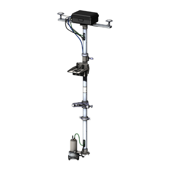
M3 Bathy Pole Mount The M3 Pole Mount is designed for installation on small vessels of opportunity. Normally the Pole Mount is installed on the vessel’s port side. The top of the Pole Mount is above water and holds the Surface Interface Unit. The bottom of the Pole Mount is below water and holds the Motion Reference Unit and Sonar Head in position during a survey. -
Page 16: Scope Of Supply
Additional optional items, page 16 Basic items provided with a standard delivery To assemble a complete M3 Bathy system, you will need a set of system units. The main units required are provided with the standard delivery. Other required units may be purchased from Kongsberg Mesotech or obtained locally. - Page 17 M3 Sonar Processor laptop Power cords and supply Mouse USB with software and documentation The M3 Bathy comes with only one Motion Reference Unit. Note For the exact contents of your order, refer to the packing lists. Operational software Operational software is provided on a suitable media. If the Sonar Processor is purchased from Kongsberg, it is also installed on the computer.
-
Page 18: Additional Required Items
M3 Bathy Installation Manual Additional required items The M3 Bathy delivery will contain the mains parts required for basic operation. Some of these can be ordered from Kongsberg, others may be purchased locally. Sound speed sensor A sound speed sensor is required to accurately measure in-water speed near the Sonar Head. -
Page 19: General Safety Rules
• You must always switch off all power before installation or maintenance work on the M3 Bathy system. Use the main circuit breaker, and label the breaker with a warning sign that informs others that maintenance or installation work is in progress on the system. -
Page 20: Installation Requirements
The Uninterruptible Power Supply (UPS) must have the capacity to independently maintain power to the M3 Bathy for a minimum of 10 minutes. This ensures that the M3 Bathy can be switched off in a controlled manner in the event of a power failure. -
Page 21: Support Information
– At least 2 meters (6.6 feet) from the path of radar beams. A typical radar beam spreads 20 degrees above and below the plane containing the radiating element. • Protect the M3 Bathy with a suitably rated fuse or circuit breaker. The power supply should be adequately filtered to minimize equipment exposure to high-voltage transients that may occur during engine start or when other high-power equipment is used on board of the vessel. -
Page 22: Preparations
M3 Bathy Installation Manual Preparations Topics Installation summary, page 21 Tools and equipment required for M3 Bathy installation, page 22 922-00017001/1.2... -
Page 23: Installation Summary
An overall installation procedure is provided below. Note In order to obtain maximum safety and M3 Bathy performance, it is very important that the installation procedures in this manual are complied to. You must do the tasks in the order they are described. -
Page 24: Tools And Equipment Required For M3 Bathy Installation
• Velcro wraps or electrical tape • A utility knife If you wish to install the M3 Bathy without drilling holes into your vessel hull, you will need: • A length of rope or hardware (to affix the board to the vessel) •... -
Page 25: Installing The Pole Mount
Installing the Pole Mount Installing the Pole Mount Topics Preparing for Pole Mount installation, page 24 Installing the Pole Mount, page 27 Aligning the Pole Mount, page 32 922-00017001/1.2... -
Page 26: Preparing For Pole Mount Installation
Mast Clamp assembly to the vessel. • The Pole Mount tool kit has all the specific tools you need to install the Pole Mount. • If you wish to install the M3 Bathy without drilling holes into your vessel hull, you will need: –... - Page 27 Installing the Pole Mount Procedure Ensure the vessel is docked on its port side and there is room to work on the dock to set up the Pole Mount. Unpack the Pole Mount hardware. To determine where to install the Pole Mount, place the Mast Clamp assembly onto the gunwale, as close to amidships as possible.
- Page 28 M3 Bathy Installation Manual Bolt the assembly in place. If the Mast Clamp assembly still protrudes out from the gunwale, install the right-angle bracket. Align the right-angle bracket beneath the Mast Clamp assembly and flush against the hull. Bolt the right-angle bracket to the Mast Clamp assembly through the two cutouts.
-
Page 29: Installing The Pole Mount
Collar, Stabilizer Feet, and Attachment Ring completes the Pole Mount installation. Prerequisites • To install the M3 Bathy, you must have basic mechanical skills. At least two people must do the installation together. • You will need the vessel dimensions, including the draft. The vessel draft will be used to determine how deep below the waterline the bottom of the mast will need to go. - Page 30 Failure to do this may result in thread galling of the pole sections or inability to remove screws! Context The M3 Bathy Pole Mount comes in two cases. One is a large bag containing the three pole sections and the antenna bar. The other is a hard-shell case containing the rest of the Pole Mount hardware and tools.
- Page 31 Installing the Pole Mount Position the Mast Clamp so it is locked in the horizontal position. Remove the spring clip (A). Pivot the Mast Clamp so it is in the horizontal position. Store the spring clip in the hole (B). Insert the Top Mast into the Mast Clamp.
- Page 32 M3 Bathy Installation Manual Attach the Stop Collar to the Mast Clamp. Slide the Stop Collar (A) onto the Top Mast. Bolt in place using the 4 hole from the top of the mast. Ensure the bolt is fully engaged, going all the way into the mast hole.
- Page 33 Installing the Pole Mount Ensure the bolt (A) is fully engaged, going all the way into the mast hole. Install the Attachment Ring to the 2 hole from the bottom of the mast. Slide the Attachment Ring onto the Bottom Mast. Bolt in place using the 2 hole from the bottom of the mast.
-
Page 34: Aligning The Pole Mount
Pole Mount when the vessel is underway. Prerequisites • To install the M3 Bathy, you must have basic mechanical skills. At least two people must do the installation together. • The Pole Mount tool kit has all the specific tools you need to install the Pole Mount. - Page 35 Installing the Pole Mount Confirm the Stabilizer Feet is bolted in place and does not move when attempting to slide it up or down the pole. Confirm the Stabilizer Feet bolt is tightened with an Allen key. Confirm the Attachment Ring is bolted in place and does not move when attempting to slide it up or down the pole.
- Page 36 M3 Bathy Installation Manual Move the Pole Mount into a vertical position. Allow the Mast Clamp to pivot by confirming the spring clip is released. Slowly release the second line and/or deployment line allowing the mast to rotate so it rests vertically.
- Page 37 Installing the Pole Mount Check the mast is vertical, then insert two of the bolts into the Mast Clamp plate to restrict mast rotation fore/aft. There are three possible bolt configurations to secure the mast, depending on the gunwale configuration. Gunwale on port side with forward up-slope Gunwale that is level Gunwale on starboard side with forward up-slope...
- Page 38 M3 Bathy Installation Manual Note If there is still excessive movement at dockside or later when underway, this may require a tension line to pull in and hold the Stabilizer Feet. Attach this line to the Attachment Ring then pass the rope under the vessel and tie off on a cleat on the opposite side of the vessel.
-
Page 39: Installing The Sonar Head And Motion Reference Unit
Installing the Sonar Head and Motion Reference Unit Installing the Sonar Head and Motion Reference Unit Topics Attaching the Seatex Motion Reference Unit to the Pole Mount’s bottom flange, page 38 Installing the Sonar Head onto the bracket assembly, page 41 Attaching the Sonar Head and Motion Reference Unit to the Pole Mount, page 43 922-00017001/1.2... -
Page 40: Attaching The Seatex Motion Reference Unit To The Pole Mount's Bottom Flange
Attaching the Seatex Motion Reference Unit to the Pole Mount’s bottom flange If you have purchased a Seatex Motion Reference Unit (MRU) for your M3 Bathy system, it is installed on the Downlooking bracket, along with the bottom flange of the Pole Mount. - Page 41 Installing the Sonar Head and Motion Reference Unit Context The following parts are required to install the Motion Reference Unit. Seatex MRU Pole Mount’s bottom flange Downlooking bracket Procedure Identify the Downlooking bracket. One side (facing up) has recessed holes for attaching the MRU. Orient the Downlooking bracket so that the recessed holes are facing up, and the anode location notch is on the right, as shown in the image.
- Page 42 M3 Bathy Installation Manual Ensure the bottom flange is oriented with respect to the bracket, as shown in the image. Caution Marine grade grease or anti-seize compound (included) must be applied to all fasteners during assembly. Attach the MRU to the bracket using the four flathead metric fasteners.
-
Page 43: Installing The Sonar Head Onto The Bracket Assembly
Installing the Sonar Head and Motion Reference Unit Related topics Installing the Sonar Head onto the bracket assembly, page 41 Installing the Sonar Head onto the bracket assembly The Sonar Head attaches to the Motion Reference Unit (MRU) bracket assembly. Prerequisites •... - Page 44 M3 Bathy Installation Manual Place the plastic isolation pad (C) on top of the Sonar Head. Lay the MRU bracket assembly on top of the Sonar Head with the Sonar Head connectors (A) pointing towards the bottom flange. Insert the plastic shoulder washers into all four bracket holes.
-
Page 45: Attaching The Sonar Head And Motion Reference Unit To The Pole Mount
• The Sonar Head must be attached to the Motion Reference Unit bracket assembly to form a bottom flange assembly. • To install the M3 Bathy, you must have basic mechanical skills. At least two people must do the installation together. Be careful not to drop the bottom flange assembly when attempting to attach it to the lower mast section. - Page 46 M3 Bathy Installation Manual Caution Be aware the Motion Reference Unit and the M3 Sonar Head are easily damaged through mishandling – in particular the polyurethane face of the Sonar Head transducer. Procedure Recover the Pole Mount. Remove the bolts installed in the Mast Clamp plate (A).
- Page 47 Installing the Sonar Head and Motion Reference Unit Rotate the end of the Pole Mount away from the vessel and position the bottom mast on the dock. Note You will need enough space on the dock to attach the bottom flange assembly to the bottom mast.
- Page 48 M3 Bathy Installation Manual A bowline knot forms a secure loop that will not jam and is easy to tie and untie. Result The Sonar Head and Motion Reference Unit are attached to the Pole Mount. Further requirements You are now ready to install the Surface Interface Unit.
-
Page 49: Installing The Surface Interface Unit
Installing the Surface Interface Unit Installing the Surface Interface Unit Topics Assembling the Surface Interface Unit, antenna bar, and antennas, page 48 Attaching the Surface Interface Unit to the Pole Mount, page 49 922-00017001/1.2... -
Page 50: Assembling The Surface Interface Unit, Antenna Bar, And Antennas
The Surface Interface Unit and the antenna bar attach to the top of the Pole Mount. Prerequisites • To install the M3 Bathy, you must have basic mechanical skills. At least two people must do the installation together. • The Surface Interface Unit accessory kit has all the specific tools you need to install the Surface Interface Unit. -
Page 51: Attaching The Surface Interface Unit To The Pole Mount
The Surface Interface Unit attaches to the top of the Pole Mount. Prerequisites • To install the M3 Bathy, you must have basic mechanical skills. At least two people must do the installation together. • The Surface Interface Unit accessory kit has all the specific tools you need to install the Surface Interface Unit. - Page 52 M3 Bathy Installation Manual Procedure Attach the Surface Interface Unit onto the Top Mast section of the Pole Mount. Align the GPS antenna bar parallel with the vessel’s direction of motion. The cables exiting the Surface Interface Unit will be facing vessel aft (back).
-
Page 53: Installing The M3 Sonar Processor
Installing the M3 Sonar Processor Installing the M3 Sonar Processor Topics Setting up the Sonar Processor, page 52 Installing the express card and adapter, page 54 922-00017001/1.2... -
Page 54: Setting Up The Sonar Processor
M3 Bathy Installation Manual Setting up the Sonar Processor The Sonar Processor is the computer that controls the M3 Bathy system. It is a vital part of the M3 Bathy Multibeam echo sounder. Prerequisites Caution All Sonar Processor parts, along with the laptop, power supply, and Surface Interface Unit power supply are rated for indoor use. - Page 55 Installing the M3 Sonar Processor Procedure Locate a work space to set up the M3 Sonar Processor laptop computer, mouse, and power supply. Note The cables provided allow runs up to 50 feet (15 m) between the laptop and the Surface Interface Unit.
-
Page 56: Installing The Express Card And Adapter
M3 Bathy Installation Manual Installing the express card and adapter The express card connects the computer to the GPS antennas and sound velocity sensor (if you have one). The adapter connects the computer to the Motion Reference Unit. Prerequisites You will need the following components. You can find them in the Surface Interface Unit accessory kit. - Page 57 Installing the M3 Sonar Processor Attach the Moxa UPort 1150 to a USB port on the laptop computer. Store the boxes for the express card and adapter back in the case for the Surface Interface Unit accessory kit. Result The express card and adapter are connected to the laptop. Further requirements You are now ready to connect all the cables.
-
Page 58: Cable Layout And Interconnections
M3 Bathy Installation Manual Cable layout and interconnections Topics Read this first, page 57 Cable plan, page 58 List of M3 Bathy cables, page 59 Installing the M3 Bathy cables, page 60 Cable drawings and specifications, page 72 922-00017001/1.2... -
Page 59: Read This First
Kongsberg Mesotech Limited accepts no responsibility for damage to the system, or reduced operational performance, when this is caused by improper wiring. Note Before you perform the M3 Bathy cabling, ensure that the mains circuit breaker for the system is switched off. 922-00017001/1.2... -
Page 60: Cable Plan
Breakout box for Sonar Head and Surface Interface Unit Power RS422 to USB Adapter 4-Port RS232 Express Card Adapter M3 Sonar Processor laptop computer Mouse Helmsman display (*not included as part of the standard M3 Bathy system) Related topics List of M3 Bathy cables, page 59 922-00017001/1.2... -
Page 61: List Of M3 Bathy Cables
Cable layout and interconnections List of M3 Bathy cables A set of cables is required to connect the M3 Bathy units to each other, and to the relevant power source(s). Cable From GPS Antenna Surface Interface Unit Motion Reference Unit (Connector A) -
Page 62: Installing The M3 Bathy Cables
M3 Bathy Installation Manual Installing the M3 Bathy cables Topics Connecting the GPS antennas to the Surface Interface Unit, page 60 Connecting the Surface Interface Unit to the Sonar Head and Motion Reference Unit, page 61 Connecting the Surface Interface Unit to the Sonar Processor, page 68 Connecting the GPS antennas to the Surface Interface Unit The GPS antenna cables from the Surface Interface Unit are attached to the GPS antennas. -
Page 63: Connecting The Surface Interface Unit To The Sonar Head And Motion Reference Unit
Cable layout and interconnections Connecting the Surface Interface Unit to the Sonar Head and Motion Reference Unit Two long cables leading from the Surface Interface Unit are threaded through the Pole Mount. These cables are connected to the Sonar Head and Motion Reference Unit (MRU) to provide power and convey telemetry data. - Page 64 M3 Bathy Installation Manual Feed both cables through the Pole Mount mast sections by making use of the enlarged cut-outs (A) at either end of the Pole Mount. Caution Ensure the cables are not damaged during installation and deployment. Bending the cables excessively may weaken or break them.
- Page 65 Cable layout and interconnections Check that the MRU and MRU cable connector are clean. If not, clean off the connector with compressed air, a lint-free cloth, or swab. Apply a small amount of o-ring grease to the rubber on the Motion Reference Unit’s cable connector before mating.
- Page 66 Replacing the o-ring in the sonar cable connector A cable with a 10-pin cable connector connects to the Sonar Head. When installing the M3 Bathy, you must check if the o-ring is properly installed. If the o-ring is missing or damaged, it will need to be replaced.
- Page 67 Cable layout and interconnections The following tools and consumables are not included and must be purchased locally. • Dove-tail O-ring Installation Tool (DOIT) • O-ring pick tool • O-ring grease • Swabs • Isopropyl Alcohol 922-00017001/1.2...
- Page 68 M3 Bathy Installation Manual Procedure Remove the o-ring from the Cable Connector Plug. Use the Parker o-ring picks to extract the o-rings from the Cable Connector Plugs and Flanged Connector Receptacle. Clean the o-ring surface with Q-Tips and Isopropyl Alcohol.
- Page 69 Cable layout and interconnections Grease the replacement o-ring with a small amount of o-ring grease. Fit the o-ring onto the DOIT and slide it to the end. 922-00017001/1.2...
-
Page 70: Connecting The Surface Interface Unit To The Sonar Processor
M3 Bathy Installation Manual Using the DOIT, fit the o-ring back onto the Cable Connector Plug or Flanged Connector Receptacle. Install the o-ring in the Cable Connector Plug by aligning the key and pressing into the connector. Rotating the DOIT when pulling it out can help ensure the o-ring stays in place. - Page 71 Cable layout and interconnections • Ethernet patch cable • RS232 splitter cable DB9F x 2 to DB9M x1 • Serial extension cable All the listed cables are found in the Surface Interface Unit accessory kit. Note Protective caps are provided for all DB9 serial sensor connectors. Ensure they are stored in a safe place and installed on the breakout box when the system is not being used and during storage and transport.
- Page 72 M3 Bathy Installation Manual Connect the one GPS sensor cable to the P1 and P2 cables on the 4-port RS232 Express Card (A). Using the RS232 splitter cable, connect the two DB9F connectors to the 4-port RS232 Express Card cables labelled P1 and P2.
- Page 73 Cable layout and interconnections Connect the other end of the serial extension cable to the Moxa UPort 1150 USB to RS422 adapter (A). Result The Sonar Processor is connected to the two breakout boxes leading to the Surface Interface Unit. 922-00017001/1.2...
-
Page 74: Cable Drawings And Specifications
M3 Bathy Installation Manual Cable drawings and specifications Topics Sonar Head - SEA CON MINK-10-CCPL: Power and Ethernet, page 72 Sonar Head - SEA CON MIND-4-CCP: Synchronization, page 73 Motion Reference Unit - Seatex with 50m subsea bottle: Connector A, page 73... -
Page 75: Sonar Head - Sea Con Mind-4-Ccp: Synchronization
Cable layout and interconnections Sonar Head - SEA CON MIND-4-CCP: Synchronization This is an optional cable only used if you have purchased a Sonar Head that supports Sync/1PPS Pin Functions • : DGND (white) Pin 1 • : PRI_SYNC (green) Pin 2 •... -
Page 76: Setting To Work
Setting to work Topics Setting to work summary, page 75 Verifying that the M3 Bathy is ready for operational use, page 76 Powering up the M3 Bathy for the first time, page 79 Configuring the M3 Bathy for operational use, page 81... -
Page 77: Setting To Work Summary
To check that the M3 Bathy fulfills all operational and functional requirements, specific tests are provided. Create a backup with the M3 Bathy configuration and software installation. Once all M3 Bathy configuration and testing have been finalized, it is good practice to back up the configuration data and software installation. 922-00017001/1.2... -
Page 78: Verifying That The M3 Bathy Is Ready For Operational Use
Verifying that all cables and hardware are properly installed, page 77 Verifying that operational power is correct The M3 Bathy operates on AC power from the vessel’s mains supply. Before you apply AC power to any M3 Bathy unit, you must verify the power is correct. -
Page 79: Verifying That All Cables And Hardware Are Properly Installed
Setting to work Verifying that all cables and hardware are properly installed The M3 Bathy relies on communication between each system unit, and between the M3 Bathy and external devices. It is very important that all cables are correctly installed, that the proper cable types have been used, and that all cables are connected correctly. - Page 80 Check that the Pole Mount does not move when the top of the pole is wiggled. For each cable that is in used on the M3 Bathy: Verify that the cable has been installed. Verify that the connections made at each end of the cable are correct.
-
Page 81: Powering Up The M3 Bathy For The First Time
You are now ready to power up the M3 Bathy for the first time. Powering up the M3 Bathy for the first time In order to use the M3 Bathy, you must turn it on. You must power up the Sonar Processor and Surface Interface Unit. - Page 82 Confirm the power indicator light on the Surface Interface Unit’s power supply is turned on. Note It will take up to 15 minutes for the MRU and the GPS to achieve full accuracy. Further requirements You are now ready to configure the M3 Bathy for operational use. 922-00017001/1.2...
-
Page 83: Configuring The M3 Bathy For Operational Use
Configuring the M3 Bathy for operational use Topics Defining the IP address on the Sonar Processor network adapter, page 81 Installing the M3 Bathy operational software, page 82 Configuring data export to third-party software, page 83 Defining the IP address on the Sonar Processor network... -
Page 84: Installing The M3 Bathy Operational Software
Installing the M3 Bathy operational software If your M3 Bathy Multibeam echo sounder is provided with a Sonar Processor, the M3 Bathy software has already been installed. If you intend to use your own computer, you must install the software yourself. -
Page 85: Configuring Data Export To Third-Party Software
Confirm the software finishes launching without any error windows appearing. Configuring data export to third-party software If you ordered third-party software with your M3 Bathy system, it is pre-installed on the Sonar Processor. All external heading, motion, and position sensors — including the GPS, Gyro, and Motion Reference Unit —... - Page 86 M3 Bathy Installation Manual Result You are now ready to run your third-party software. Refer to your third-party user documentation for operating information. 922-00017001/1.2...
-
Page 87: Testing The M3 Bathy Operational Functionality
Setting to work Testing the M3 Bathy operational functionality Topics Testing the 4–Port RS232 Express Card, page 85 Testing the Moxa UPort 1150 RS422 to USB adapter, page 87 Testing the GPS receiver, page 88 Testing the Motion Reference Unit data output, page 89 Testing the 4–Port RS232 Express Card... - Page 88 M3 Bathy Installation Manual Double click and check that the four COM ports on the Ports (COM & LPT) express card are shown. Note If the ports fail to appear, reinsert the express card and scan for hardware changes →...
-
Page 89: Testing The Moxa Uport 1150 Rs422 To Usb Adapter
Setting to work Testing the Moxa UPort 1150 RS422 to USB adapter An RS422 to USB adapter is supplied with the Surface Interface Unit accessory kit. There is no hardware configuration of the unit required (e.g. jumper or switch settings). The computer serial port settings for the Moxa UPort 1150 are set in software at the factory before shipping. -
Page 90: Testing The Gps Receiver
Testing the GPS receiver The program PocketMax3 is used to configure and test the GPS receivers so that they communicate successfully with the M3 Bathy units. Context If PocketMax3 fails to connect to the GPS, connect the RS232 connector labeled P1 directly to the breakout box for the GPS. -
Page 91: Testing The Motion Reference Unit Data Output
Setting to work Port: COM11 Baud Rate: 115200 Mode: Normal Click to connect to the GPS. Search Click on the Precision tab. Confirm the plotted position is within the limits required for the survey. Close PocketMax3. Testing the Motion Reference Unit data output To test the Motion Reference Unit (MRU) data output, you can check the TSS1 data-string output quality flag. - Page 92 M3 Bathy Installation Manual Example :020010 -0001F 0023 -0169, where the Quality Flag = F (full aided mode) 922-00017001/1.2...
-
Page 93: Testing The M3 Software
Setting to work Testing the M3 software Topics Testing the connection to the sensors, page 91 Testing the operation of the Sonar Head, page 92 Testing the Sonar Head telemetry, page 94 Testing the connection to the sensors There is a built-in test function in the M3 software that allows you to test the sensors and confirm that the sensor data is being correctly received. -
Page 94: Testing The Operation Of The Sonar Head
M3 Bathy Installation Manual Click Stop Test Test that the heading output from the GPS is being correctly received. Select the sensor device in port and click PC COM 11 Test Device Confirm the NMEA string for HDT is displayed in the box. - Page 95 Setting to work Click the “i” icon in the sonar image display window to open the Information Widget. Confirm the sensor data is updating in the Information Widget. → Click Sonar Apps Profiling - Bathy Right click on the sonar image and choose an appropriate range.
-
Page 96: Testing The Sonar Head Telemetry
M3 Bathy Installation Manual Click on Active located on the Status Bar (lower right). Confirm that all items listed under the M3 Sonar show green check boxes. If any items are shown with an X with a red circle, it usually means the device has failed to connect. - Page 97 Setting to work Procedure Limit the Ethernet adapter link speed to 100 Mbps. In the bottom-left corner of your desktop, type “view network connections” into the Cortana search box, then press Enter Observe that the Control Panel opens. Right click on the connected to the M3 Sonar Head, then Local Area Connection select...
-
Page 98: Creating A Backup With The M3 Configuration And Software Installation
Creating a backup with the M3 configuration and software installation As the M3 software is pre-configured at the factory, you will lose all the M3 Bathy settings if you re-install the software. We recommend creating a backup in case you need to restore your settings at a later time. -
Page 99: Powering Down The M3 Bathy
Sonar Processor. Powering down the M3 Bathy The M3 Bathy is not provided with an on/off switch. Context When you do not use the M3 Bathy, switch off the entire system. Procedure → If you are running the sonar, click in the M3 software. -
Page 100: Repacking The M3 Bathy
M3 Bathy Installation Manual Repacking the M3 Bathy Topics Repacking the Sonar Processor, page 99 Repacking the Surface Interface Unit, page 100 Repacking the Sonar Head and Motion Reference Unit, page 102 Repacking the Pole Mount and accessories, page 104... -
Page 101: Repacking The Sonar Processor
Repacking the M3 Bathy Repacking the Sonar Processor The Sonar Processor comes in a hard-shell equipment case. Prerequisites • All cables must be disconnected and protective dust caps placed on all connectors. • Ensure the laptop and other items are dry before packing away. -
Page 102: Repacking The Surface Interface Unit
M3 Bathy Installation Manual Close the laptop (A) and pack it in the top level of the equipment case. Pack the USB drive (B) on top of the laptop. Pull down the foam lid (C) and pack the M3 Sonar Operator manual in the top of the case. - Page 103 Repacking the M3 Bathy • All cables must be disconnected and protective dust caps placed on all connectors. • The Pole Mount with the Sonar Head and Motion Reference Unit attached must be oriented in a horizontal position and tied down to prevent damage to the units.
-
Page 104: Repacking The Sonar Head And Motion Reference Unit
M3 Bathy Installation Manual Repacking the Sonar Head and Motion Reference Unit After installation of the Motion Reference Unit (MRU), please save the transportation container. To maintain warranty validity, the MRU must be shipped in this container for service or repair. The Sonar Head comes in a hard-shell case. - Page 105 Pack the Sonar Head accessory kit (B) into the side pocket of the foam insert in the hard-shell case. Pull down the foam lid (C) and pack the M3 Bathy Installation Manual in the top of the case. Pack the Seatex MRU into its original transportation container.
-
Page 106: Repacking The Pole Mount And Accessories
Repacking the Pole Mount and accessories The M3 Bathy Pole Mount comes in two cases. One is a large bag containing the three pole sections and the antenna bar. The other is a hard-shell case containing the rest of the Pole Mount hardware and tools. - Page 107 Repacking the M3 Bathy Pack the Mast Clamp assembly (A) into the second level of the case. Pack the Pole Mount’s bottom flange (A) into the third level of the case. 922-00017001/1.2...
- Page 108 M3 Bathy Installation Manual Pack the tool kit case (A), clamps, and wrench (B) in the fourth level of the case. Pack the three pole sections (plus the GPS antenna bar from the Surface Interface Unit) in the blue canvas bag.
-
Page 109: Drawing File
Drawing file About the drawings in the drawing file Relevant drawings related to the installation and/or maintenance of the M3 Bathy are provided for information purposes only. The drawings are not to scale. Unless otherwise specified, all measurements are in inches (in). -
Page 110: Mast Clamp Assembly Outline Dimensions
M3 Bathy Installation Manual Mast Clamp assembly outline dimensions Document number: 437-00187002 922-00017001/1.2... -
Page 111: Pole Mount Outline Dimensions
Drawing file Pole Mount outline dimensions Document number: 922-80011001 922-00017001/1.2... -
Page 112: Surface Interface Unit Outline Dimensions
M3 Bathy Installation Manual Surface Interface Unit outline dimensions Document number: 922-60021001 922-00017001/1.2... -
Page 113: Seatex Motion Reference Unit Outline Dimensions
Drawing file Seatex Motion Reference Unit outline dimensions Document number: 422-44131001 922-00017001/1.2... -
Page 114: Technical Specifications
M3 Bathy Installation Manual Technical specifications Topics Introduction to technical specifications, page 113 Interface specifications, page 114 Performance specifications, page 116 Mechanical specifications, page 118 Power requirements, page 119 Environmental requirements, page 120 Minimum computer requirements, page 121 Minimum technical requirements for helmsman display, page 121... -
Page 115: Introduction To Technical Specifications
Technical specifications Introduction to technical specifications These technical specifications summarize the main functional and operational characteristics of the M3 Bathy Multibeam echo sounder. It also provides information related to power requirements, physical properties and environmental conditions. Note At Kongsberg Mesotech, we are continuously working to improve the quality and performance of our products. -
Page 116: Interface Specifications
M3 Bathy Installation Manual Interface specifications The M3 Bathy Multibeam echo sounder will interface with peripheral systems and sensors using standard and/or proprietary datagram formats. Supported datagram formats for position information The M3 Bathy supports the following datagram formats for position information. - Page 117 This is a third-party proprietary datagram format for heading, speed, and motion. It was created by iXSea (http://www.ixblue.com) for use with their Octans gyrocompass. Supported datagram formats for sound speed sensors The M3 Bathy supports the following datagram format from a sound speed sensor. • Valeport format This is a third-party proprietary datagram format.
-
Page 118: Performance Specifications
• .ALL This is the proprietary Kongsberg EM series datagram format. The M3 software can output this data format to be compatible with third-party post-processing software. Performance specifications These performance specifications summarize the main functional and operational characteristics of the M3 Bathy system. - Page 119 Technical specifications • : 3° Along track field of view • : up to 256 Number of beams • : up to 40 Hz Update rate • : Equiangular Beam spacing Position and Heading Sensor • : RS232 Output format •...
-
Page 120: Mechanical Specifications
M3 Bathy Installation Manual Mechanical specifications These mechanical specifications summarize the physical properties of the M3 Bathy system. Note For more detailed information about the physical dimensions, see the Drawing file. Sonar Processor The Sonar Processor uses a high-quality commercial-off-the-shelf laptop computer workstation. -
Page 121: Power Requirements
Height (three poles) • : 31 kg Weight Power requirements These power characteristics summarize the supply power requirements for the M3 Bathy system. The total power required for the system is 280 W (max). Sonar Processor • : 120/240 VAC Power adapter input voltage •... -
Page 122: Environmental Requirements
This computer is intended to be installed inside in an area suitable for extended human habitation. Contact your Kongsberg Mesotech representative for information about the current model that is delivered with your M3 Bathy system. Surface Interface Unit •... -
Page 123: Minimum Computer Requirements
Technical specifications Minimum computer requirements Although a computer can be ordered from Kongsberg Mesotech as a part of the M3 Bathy delivery, it is also possible to purchase one locally. If you purchase a computer locally, make sure that the chosen model meets the functional and technical requirements. - Page 124 : These must match the video output formats provided by the Sonar Video interface Processor. The Sonar Processor offers video output on several formats. Investigate your options before purchasing a display. • : This depends on personal and operational preferences. Physical size The M3 Bathy software supports 9:16 displays. 922-00017001/1.2...
- Page 125 Index Index 4-Port RS232 Express Card computer testing ............85 minimum requirements ........121 configuring software ............. 83 about installation drawings ........107 purpose of this manual ........7 datagram formats registered trademarks........7 depth information ......... 115 software license ..........7 gyro information ..........
- Page 126 M3 Bathy Installation Manual testing ............88 Surface Interface Unit ......... 48–49 gyro information interconnection datagram formats ......... 114 procedures ......... 60–61, 68 interconnection cables list ............59 interface specifications ..........114 hardware interface cables verify correct installation ......... 77 verify correct connections ........
- Page 127 Index datagram formats ......... 115 Motion Reference Unit performance installing ..........38, 43 specifications ..........116 introduction ..........12 peripheral systems outline dimensions........111 interface specifications ........114 overview ............ 12 Pole Mount purpose ............12 aligning............32 repacking........... 102 installing ............
- Page 128 M3 Bathy Installation Manual processed data Sonar Processor formats ............. 116 installing ..........52, 54 publication introduction ..........11 purpose ............7 overview .............11 target audience ..........7 purpose ............11 purpose repacking............ 99 Motion Reference Unit........12 sound speed Pole Mount ..........13 datagram formats .........
- Page 129 Index this manual............ 7 technical specifications ..........113 technical requirements computer ........... 121 display ............121 technical specifications interface specifications ........114 testing 4-Port RS232 Express Card ......85 GPS receiver..........88 Motion Reference Unit data output...... 89 Moxa UPort 1150 RS422 to USB adapter....87 sonar and sensors .........
- Page 130 ©2017 Kongsberg Mesotech...
Need help?
Do you have a question about the M3 Bathy and is the answer not in the manual?
Questions and answers