Table of Contents
Advertisement
Available languages
Available languages
Quick Links
CUSTOMER SERVICE
SERVICIO AL CLIENTE
USA: 1-877-617-3501
Mexico: 01 800 843 1111
www.powerstroketools.com
NEUTRAL FLOATING
NEUTRAL DE FLOTACIÓN
Do not use E15 or E85 fuel (or fuel containing greater than 10% ethanol) in this product. It is a
violation of federal law and will damage the unit and void your warranty.
No utilice combustibles E15 o E85 (ni combustibles que contengan más de 10 % de etanol) con
este producto. Esto constituye una violación a la ley federal, dañará la unidad y anulará la garantía.
TABLE OF CONTENTS
Important Safety Instructions ................................................3-4
Specific Safety Rules ...............................................................4
Symbols ................................................................................5-7
Electrical ...............................................................................8-9
Features ............................................................................10-11
Assembly ...............................................................................11
Operation ..........................................................................12-15
Maintenance .....................................................................15-17
Troubleshooting .....................................................................18
Warranty .................................................................................19
Parts Ordering / Service ........................................... Back Page
WARNING:
To reduce the risk of injury, the user must
read and understand the operator's manual before using this
product.
SAVE THIS MANUAL FOR
FUTURE REFERENCE
OPERATOR'S MANUAL
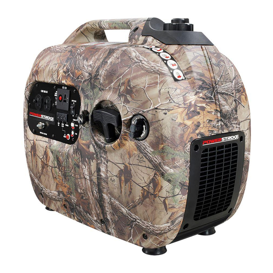
DIGITAL INVERTER GENERATOR
GENERADOR DEL INVERSOR DE DIGITACES
NOTICE
Instrucciones de seguridad importantes .............................3-4
Reglas de seguridad específicas ............................................ 4
Símbolos ..............................................................................5-7
Aspectos eléctricos .............................................................8-9
Características .................................................................10-11
Armado ................................................................................. 11
Funcionamiento ...............................................................12-15
Mantenimiento .................................................................15-17
Corrección de problemas ..................................................... 18
Garantía ................................................................................ 19
Pedidos de piezas/ servicio ............................... Pág. posterior
usuario debe leer y comprender el manual del operador antes
de usar este producto.
MANUAL DEL OPERADOR
AVISO
ÍNDICE DE CONTENIDO
Para reducir el riesgo de lesiones, el
GUARDE ESTE MANUAL
PARA FUTURAS CONSULTAS
PSi2100
Series/Serie
Advertisement
Table of Contents

Related Manuals for Power Stroke PSi2100 Series


Summary of Contents for Power Stroke PSi2100 Series
-
Page 1: Table Of Contents
OPERATOR’S MANUAL MANUAL DEL OPERADOR DIGITAL INVERTER GENERATOR GENERADOR DEL INVERSOR DE DIGITACES PSi2100 Series/Serie CUSTOMER SERVICE SERVICIO AL CLIENTE USA: 1-877-617-3501 Mexico: 01 800 843 1111 www.powerstroketools.com NEUTRAL FLOATING NEUTRAL DE FLOTACIÓN NOTICE AVISO Do not use E15 or E85 fuel (or fuel containing greater than 10% ethanol) in this product. It is a violation of federal law and will damage the unit and void your warranty. - Page 2 See this fold-out section for all of the figures referenced in the operator’s manual. Consulte esta sección desplegable para ver todas las figuras a las que se hace referencia en el manual del operador.
- Page 3 Fig. 1 A - Side cover (cobertura lateral) H - Low oil indicator (luz de bajo nivel de O - Spark plug cover (cubierta de la bujía) B - Choke knob (perilla del anegador) lubricante) P - Muffler with exhaust diffuser screen C - Starter grip and rope (mango del arrancador...
- Page 4 Fig. 5 Fig. 11 Fig. 8 A - Auto idle switch (interruptor de ralentí automático) B - Off (apagado) C - On (encendido) A - Starter grip and rope (mango del arrancador y cuerda) Fig. 9 A - Funnel (embudo) B - Vented fuel cap (tapa del tanque ventilación) Fig.
- Page 5 Fig. 14 Fig. 16 Fig. 18 A - Screw (tornillo) B - Air filter cover (tapa del filtro de aire) C - Air filter (filtro de aire) A - Vented fuel cap (tapa del tanque ventilación) B - Container (recipiente) Fig.
- Page 6 To register your PowerStroke product, please visit: www.powerstroketools.com LOCATE GENERATOR AT LEAST 20 FT.* AWAY TO REDUCE THE RISK OF CARBON MONOXIDE GETTING INSIDE THE HOME * Minimum distance as recommended by U.S. Department of Health and Human Services Centers for Disease Control and Prevention (www.cdc.gov/co). Your specific home and/or wind conditions may require additional distance.
-
Page 7: Important Safety Instructions
IMPORTANT SAFETY INSTRUCTIONS Do not allow children or untrained individuals to use this unit. DANGER: Do not start or operate the engine in a confined space, Carbon Monoxide. Using a generator indoors CAN KILL building, near open windows, or in other unventilated space YOU IN MINUTES. -
Page 8: Specific Safety Rules
IMPORTANT SAFETY INSTRUCTIONS Maintain the unit per maintenance instructions in this Use only authorized replacement parts and accessories and follow instructions in the Maintenance section of this Operator’s Manual. manual. Use of unauthorized parts or failure to follow Inspect the unit before each use for loose fasteners, fuel maintenance instructions may create a risk of shock or leaks, etc. -
Page 9: Symbols
SYMBOLS The following signal words and meanings are intended to explain the levels of risk associated with this product. SYMBOL SIGNAL MEANING Indicates an imminently hazardous situation, which, if not avoided, will result DANGER: in death or serious injury. Indicates a potentially hazardous situation, which, if not avoided, could result WARNING: in death or serious injury. - Page 10 SYMBOLS Some of the following symbols may be used on this product. Please study them and learn their meaning. Proper interpretation of these symbols will allow you to operate the product better and safer. SYMBOL NAME DESIGNATION/EXPLANATION Volts Voltage Amperes Current Hertz Frequency (cycles per second)
- Page 11 SYMBOLS ENGINE LUBRICANT WARNING CHECK LUBRICANT You must add lubricant before first operating the generator. Always check the lubricant level before each operation. The lubricant level should always register between the hatched areas on the dipstick. The unit is equipped with a sensor which will automatically shut off the engine if the lubricant NOTICE AVISO level falls below a safe limit.
-
Page 12: Electrical
ELECTRICAL EXTENSION CORD CABLE SIZE Refer to the table below to ensure the cable size of the extension cords you use are capable of carrying the required load. Inadequate size cables can cause a voltage drop, which can damage the appliance and overheat the cord. Load in Watts Maximum Allowable Cord Length Current in... - Page 13 ELECTRICAL GENERATOR CAPACITY 3. Permit the generator output to stabilize (engine runs smoothly and attached device operates properly). Make sure the generator can supply enough continuous 4. Plug in and turn on the next load. (running) and surge (starting) watts for the items you will power at the same time.
-
Page 14: Features
FEATURES PRODUCT SPECIFICATIONS GENERATOR ENGINE Rated Voltage .........120 V AC/12 V DC Engine Type ............79cc OHV Rated Amps ..........14.1 A AC/7.5 A DC Replacement Spark Plug ........Torch A5RTC Engine Lubricant Volume........13.52 oz. Rated Running Watts ..........1,700 W Starting Watts ............2,100 W Rated Frequency ............ -
Page 15: Assembly
FEATURES ON/OFF SWITCH STARTER GRIP AND ROPE The on/off switch is used in combination with the starter The starter grip and rope is used (along with the on/off switch) grip and rope to start the generator. It is also used to turn to start the generator’s engine. -
Page 16: Operation
OPERATION NOTICE: DANGER: The exhaust diffuser on this product has not been Carbon Monoxide. Using a generator indoors CAN KILL evaluated by the USDA Forest Service and cannot be YOU IN MINUTES. used on U.S. forest lands. In addition, product users Generator exhaust contains high levels of carbon must comply with Federal, State, and local fire prevention monoxide (CO), a poisonous gas you cannot see or smell. - Page 17 OPERATION Replace and secure the fuel tank cap. the generator, remove all loads from the generator and press the reset button (see fig. 2). Add loads back to the generator Start and run the engine for at least 5 minutes to allow one at a time being careful not to exceed the generators stabilizer to treat the entire fuel system.
- Page 18 OPERATION USING THE BATTERY CHARGING CABLE STARTING THE ENGINE See Figure 12. See Figures 7 - 11. NOTICE: WARNING: On a level surface with the engine off, check the lubricant The 12 V DC receptacle is designed to charge vented wet level before each use of the generator.
-
Page 19: Maintenance
OPERATION HIGH ALTITUDE OPERATION NOTE: Most batteries will be completely charged after 30 to 120 minutes. However, it is highly recommended Specific modifications are needed for high-altitude operation. that you refer to your battery manufacturer’s instructions Please contact your authorized service center for important for specific charge times. - Page 20 MAINTENANCE NOTE: Consult hazardous waste management guidelines in Inspect the exhaust diffuser for breaks or holes. Replace if your area for the proper way to dispose of used lubricant. necessary. Loosen the screws on the rear cover. Remove rear cover SPARK PLUG REPLACEMENT and set aside.
- Page 21 MAINTENANCE STORAGE When preparing the generator for storage, allow the unit to cool for 30 minutes then follow the guidelines below. STORAGE TIME PRIOR TO STORING Less than 2 months Drain gasoline from tank and dispose of in a suitable container according to state and local ordinances. 2 months to 1 year Drain fuel from carburetor.
-
Page 22: Troubleshooting
TROUBLESHOOTING PROBLEM POSSIBLE CAUSE SOLUTION On/Off switch is OFF ( O ). Turn On/Off switch to ON (I). Engine will not start. No fuel. Fill fuel tank. Stale gasoline or water in gasoline. Drain entire system and refill with fresh fuel. -
Page 23: Warranty
WARRANTY LIMITED WARRANTY WARRANTY COVERAGE OWT Industries, Inc., (the Company) warrants to the original retail purchaser that this PowerStroke Product is free from defects in material and workmanship and agrees to repair or replace, at the Company’s discretion, any defective Product free of charge within these time periods from the date of purchase: Two years, if the Product is used solely for personal, family, or household use;... - Page 24 NOTES...
- Page 25 NOTES...
- Page 26 Para registrar su producto de PowerStroke, por favor visita: www.powerstroketools.com UBIQUE EL GENERADOR A UNA DISTANCIA DE POR LO MENOS 6 M (20 PIES)* PARA REDUCIR EL RIESGO DE QUE EL MONÓXIDO DE CARBONO INGRESE EN LA CASA Distancia mínima recomendada por el Departamento de Salud y Servicios Humanos y por los Centros para el Control y la Prevención de Enfermedades de los Estados Unidos (www.cdc.gov/co).
-
Page 27: Instrucciones De Seguridad Importantes
INSTRUCCIONES DE SEGURIDAD IMPORTANTES No haga arrancar o funcionar el motor en un espacio confinado, de edificio, cerca de ventana abiertas, o en otro área sin PELIGRO: ventilación donde se puedan recolectar las emanaciones de monóxido de carbono. El monóxido de carbono, un gas incoloro, Monóxido de carbono. -
Page 28: Reglas De Seguridad Específicas
INSTRUCCIONES DE SEGURIDAD IMPORTANTES o exigirse demasiado, lo que podría producir una falla en el Mantenga la unidad según las instrucciones de mantenimiento generador. señaladas en este manual del operador. Use únicamente repuestos y accesorios autorizados y siga las Inspeccione cada vez la unidad antes de usarla para ver si tiene instrucciones descritas en la sección de Mantenimiento de este tornillos flojos, fugas de combustible, etc. -
Page 29: Símbolos
SÍMBOLOS Las siguientes palabras de señalización y sus significados tienen el objeto de explicar los niveles de riesgo relacionados con este producto. SÍMBOLO SEÑAL SIGNIFICADO Indica una situación peligrosa inminente, la cual, si no se evita, causará la muerte PELIGRO: o lesiones serias. - Page 30 SÍMBOLOS Es posible que se empleen en este producto algunos de los siguientes símbolos. Le suplicamos estudiarlos y aprender su significado. Una correcta interpretación de estos símbolos le permitirá utilizar mejor y de manera más segura el producto. SÍMBOLO NOMBRE DENOMINACIÓN / EXPLICACIÓN Voltios Voltaje...
- Page 31 SÍMBOLOS ADVERTENCIA DEL LUBRICANTE DE MOTOR CHECK LUBRICANT Antes de utilizar el generador debe abastecerlo de lubricante. Antes de utilizar la unidad, revise el nivel de lubricante. El nivel de lubricante siempre debe estar entre las áreas cubierta con rayas entrecruzadas de la varilla de nivel. La unidad está...
-
Page 32: Aspectos Eléctricos
ASPECTOS ELÉCTRICOS CALIBRE DEL CORDÓN DE EXTENSIÓN Consulte el cuadro mostrado abajo para asegurarse de que el calibre de los cordones de extensión que utilice puedan con la carga eléctrica requerida. Los cordones de calibre insuficiente pueden causar una caída de voltaje, lo cual puede quemar el dispositivo y recalentar el cordón mismo. - Page 33 ASPECTOS ELÉCTRICOS CAPACIDAD DEL GENERADOR 3. Deje que se estabilice la salida del generador (el motor marcha uniformemente y el dispositivo acoplado funciona Cerciórese que el generador pueda suministrar suficientes correctamente). vatios de potencia continua (en marcha) y de sobrecorriente 4.
-
Page 34: Características
CARACTERÍSTICAS ESPECIFICACIONES DEL PRODUCTO GENERADOR MOTOR Voltaje nominal ........120 V C.A/12 V C.C. Tipo de motor ............79cc OHV Amperaje nominal......14,1A C.A/7,5 A C.C. Bujía de repuesto ...........Torch A5RTC Potencia en marcha ..........1 700 W Volumen de aceite de motor ....0,39 l (13,52 onz.) Potencia de arranque .......... -
Page 35: Armado
CARACTERÍSTICAS TAPA DE ACEITE/VARILLA PARA MEDIR EL BOTÓN DE REAJUSTE ACEITE El botón de reajuste es utilizado para restablecer la corriente si una sobrecarga ocurre. Para restablecer la corriente, Retire la tapa de aceite/varilla para medir el aceite para desconecte todas las cargas y oprima el botón reset. revisar el nivel y añadir lubricante al motor cuando sea necesario. -
Page 36: Funcionamiento
FUNCIONAMIENTO AVISO: PELIGRO: El difusor de escape que acompaña a este producto no ha Monóxido de carbono. Usar un generador en el interior LO sido evaluado por el Servicio Forestal del Departamento MATARÁ EN POCOS MINUTOS. de Agricultura de EE. UU. y no se puede usar en terrenos Los gases de escape del generador contienen niveles altos forestales de EE. - Page 37 FUNCIONAMIENTO NOTA: Para controlar la cantidad de estabilizador de combustible botón de reajuste (vea fig. 2). Agregue cargas atrás al generador teniendo de uno en uno cuidado para no exceder la valores de que se agrega al motor, siempre mézclelo con la gasolina antes potencias de generadores.
- Page 38 FUNCIONAMIENTO ABERTURA Y CIERRE DE LA TAPA DE Para apagar el motor en una situación de emergencia: COMBUSTIBLE VENTEADA Lleve el interruptor del motor a la posición de OFF ( O ) (apagado). Vea las figuras 6 y 7. El generador tiene una tapa de combustible con una rejilla que puede abrirse y cerrarse.
-
Page 39: Mantenimiento
FUNCIONAMIENTO OPERACIÓN A ALTITUDES ELEVADAS positivo (rojo) con cuidado de no cortocircuitar las terminales. Siempre observe las advertencias de seguridad que se Deben realizarse modificaciones específicas en el caso del uso suministran con la batería. de esta unidad en alturas elevadas. Comuníquese con su centro NOTA: La mayoría de las baterías se cargarán completamente de servicio autorizado para obtener información importante sobre una vez transcurridos entre 30 y 120 minutos. - Page 40 MANTENIMIENTO NOTA: Consulte las normas de desecho de residuos peligrosos Revise si el difusor de escape tiene rasgaduras o agujeros. de su localidad para averiguar la forma correcta de desechar el Reemplácelo si es necesario. aceite usado. Afloje los tornillos de la cobertura trasera. Retire la cobertura trasera y apártela.
- Page 41 MANTENIMIENTO ALMACENAMIENTO Al preparar el generador para guardarlo, deje que la unidad se enfríe durante cinco minutos por completo y luego siga los lineamientos señalados abajo. TIEMPO DE ANTES DE GUARDARLO ALMACENAMIENTO Menos de dos meses Vacíe el tanque de combustible y colóquelo en un recipiente apropiado según lo establecido por las dis- posiciones estatales y locales.
-
Page 42: Corrección De Problemas
CORRECCIÓN DE PROBLEMAS PROBLEMA POSSIBLE CAUSE SOLUCIÓN El motor no arranca. El interruptor de encendido y apagado está Ponga el interruptor de encendido y en OFF ( O ) (apagado) apagado está en ON (I) (encendido). No hay combustible. Llene el tanque. Gasolina pasada o agua pasada en la Drene todo el sistema y reabastézcalo con gasolina. -
Page 43: Garantía
GARANTÍA GARANTIA LIMITADA COBERTURA DE LA GARANTÍA OWT Industries, Inc., (la Compañía) garantiza al comprador minorista original que este Producto PowerStroke carece de defectos en material y mano de obra, y acuerda reparar o reemplazar, a la discreción de la Compañía, cualquier Producto defectuoso sin cargo en los siguientes períodos a partir de la fecha de la compra: Dos años si el Producto se utiliza exclusivamente para fines personales, familiares o domésticos. -
Page 44: Advertencia
DIGITAL INVERTER GENERATOR GENERADOR DEL INVERSOR DE DIGITACES PSi2100 Series/Serie OPERATOR’S MANUAL MANUAL DEL OPERADOR CALIFORNIA PROPOSITION 65 SERVICE For parts or service, contact your nearest authorized service dealer. Be sure WARNING: to provide all relevant information when you call or visit. For the location of the This product, its exhaust, and other sub- authorized service dealer nearest you, please call 1-877-617-3501.
Need help?
Do you have a question about the PSi2100 Series and is the answer not in the manual?
Questions and answers