Table of Contents
Advertisement
Available languages
Available languages
Quick Links
CUSTOMER SERVICE
SERVICIO AL CLIENTE
USA: 1-877-617-3501
Mexico: 01 800 843 1111
www.powerstroketools.com
Do not use E15 or E85 fuel in this product. It is a violation of federal law and will damage the unit
and void your warranty. Only use unleaded gasoline containing up to 10% ethanol.
No utilice combustibles E15 o E85 con este producto. Esto constituye una violación a la ley federal, dañará la unidad y anulará
la garantía. Utilice únicamente gasolina sin plomo que contiene hasta 10% de etanol.
TABLE OF CONTENTS
Important Safety Instructions ................................................3-4
Specific Safety Rules ...............................................................4
Symbols ................................................................................5-7
Electrical ...............................................................................8-9
Features ............................................................................10-11
Assembly ...............................................................................11
Operation ..........................................................................12-15
Maintenance .....................................................................15-17
Troubleshooting .....................................................................18
Warranty .................................................................................19
Parts Ordering / Service ........................................... Back Page
WARNING:
To reduce the risk of injury, the user must
read and understand the operator's manual before using this
product.
SAVE THIS MANUAL FOR
FUTURE REFERENCE
OPERATOR'S MANUAL
DIGITAL INVERTER GENERATOR
GENERADOR DEL INVERSOR DE DIGITACES
NOTICE
Instrucciones de seguridad importantes .............................3-4
Reglas de seguridad específicas ............................................ 4
Símbolos ..............................................................................5-7
Aspectos eléctricos .............................................................8-9
Características .................................................................10-11
Armado ................................................................................. 11
Funcionamiento ...............................................................12-15
Mantenimiento .................................................................16-19
Corrección de problemas ..................................................... 20
Garantía ................................................................................ 21
Pedidos de piezas/ servicio ............................... Pág. posterior
usuario debe leer y comprender el manual del operador antes
de usar este producto.
MANUAL DEL OPERADOR
NEUTRAL FLOATING
NEUTRAL DE FLOTACIÓN
AVISO
ÍNDICE DE CONTENIDO
Para reducir el riesgo de lesiones, el
GUARDE ESTE MANUAL
PARA FUTURAS CONSULTAS
PSi2100RT
Advertisement
Table of Contents

Related Manuals for Power Stroke PSi2100RT


Summary of Contents for Power Stroke PSi2100RT
-
Page 1: Table Of Contents
OPERATOR’S MANUAL MANUAL DEL OPERADOR DIGITAL INVERTER GENERATOR GENERADOR DEL INVERSOR DE DIGITACES PSi2100RT CUSTOMER SERVICE SERVICIO AL CLIENTE USA: 1-877-617-3501 Mexico: 01 800 843 1111 www.powerstroketools.com NEUTRAL FLOATING NEUTRAL DE FLOTACIÓN NOTICE AVISO Do not use E15 or E85 fuel in this product. It is a violation of federal law and will damage the unit and void your warranty. - Page 2 See this fold-out section for all of the figures referenced in the operator’s manual. Consulte esta sección desplegable para ver todas las figuras a las que se hace referencia en el manual del operador.
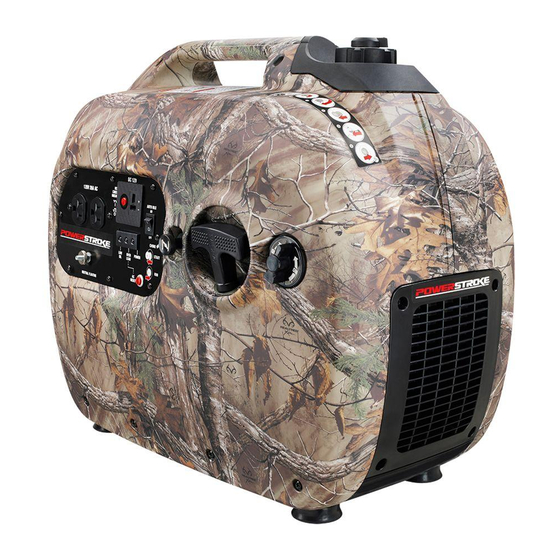
- Page 3 Fig. 1 A - Side cover (cobertura lateral) H - Low oil indicator (luz de bajo nivel de O - Spark plug cover (cubierta de la bujía) B - Choke knob (perilla del anegador) lubricante) P - Muffler with exhaust diffuser screen C - Starter grip and rope (mango del arrancador...
- Page 4 Fig. 5 Fig. 11 Fig. 8 A - Auto idle switch (interruptor de ralentí automático) B - Off (apagado) C - On (encendido) A - Starter grip and rope (mango del arrancador y cuerda) Fig. 9 A - Funnel (embudo) B - Vented fuel cap (tapa del tanque ventilación) Fig.
- Page 5 Fig. 14 Fig. 16 Fig. 18 A - Screw (tornillo) B - Air filter cover (tapa del filtro de aire) C - Air filter (filtro de aire) A - Vented fuel cap (tapa del tanque ventilación) B - Container (recipiente) Fig.
- Page 6 To register your PowerStroke product, please visit: www.powerstroketools.com LOCATE GENERATOR AT LEAST 20 FT.* AWAY TO REDUCE THE RISK OF CARBON MONOXIDE GETTING INSIDE THE HOME * Minimum distance as recommended by U.S. Department of Health and Human Services Centers for Disease Control and Prevention (www.cdc.gov/co). Your specific home and/or wind conditions may require additional distance.
-
Page 7: Important Safety Instructions
IMPORTANT SAFETY INSTRUCTIONS Do not start or operate the engine in a confined space, building, near open windows, or in other unventilated space DANGER: where dangerous carbon monoxide fumes can collect. Carbon Monoxide. Using a generator indoors CAN KILL Carbon monoxide, a colorless, odorless, and extremely YOU IN MINUTES. -
Page 8: Specific Safety Rules
IMPORTANT SAFETY INSTRUCTIONS Use only recommended or equivalent replacement parts Maintain the unit per maintenance instructions in this and accessories and follow instructions in the Maintenance Operator’s Manual. section of this manual. Use of any other parts or failure Inspect the unit before each use for loose fasteners, fuel to follow maintenance instructions may create a risk of leaks, etc. -
Page 9: Symbols
SYMBOLS The following signal words and meanings are intended to explain the levels of risk associated with this product. SYMBOL SIGNAL MEANING Indicates an imminently hazardous situation, which, if not avoided, will result DANGER: in death or serious injury. Indicates a potentially hazardous situation, which, if not avoided, could result WARNING: in death or serious injury. - Page 10 SYMBOLS Some of the following symbols may be used on this product. Please study them and learn their meaning. Proper interpretation of these symbols will allow you to operate the product better and safer. SYMBOL NAME DESIGNATION/EXPLANATION Volts Voltage Amperes Current Hertz Frequency (cycles per second)
- Page 11 SYMBOLS ENGINE LUBRICANT WARNING CHECK LUBRICANT You must add lubricant before first operating the generator. Always check the lubricant level before each operation. The lubricant level should always register between the hatched NOTICE AVISO areas on the dipstick. The unit is equipped with a sensor Add lubricant to full mark to start.
-
Page 12: Electrical
ELECTRICAL EXTENSION CORD CABLE SIZE Refer to the table below to ensure the cable size of the extension cords you use are capable of carrying the required load. Inadequate size cables can cause a voltage drop, which can damage the appliance and overheat the cord. Load in Watts Maximum Allowable Cord Length Current in... - Page 13 ELECTRICAL GENERATOR CAPACITY 3. Permit the generator output to stabilize (engine runs smoothly and attached device operates properly). Make sure the generator can supply enough continuous 4. Plug in and turn on the next load. (running) and surge (starting) watts for the items you will power at the same time.
-
Page 14: Features
FEATURES PRODUCT SPECIFICATIONS GENERATOR ENGINE Rated Voltage .........120 V AC/12 V DC Engine Type ............79cc OHV Rated Amps ..........14.1 A AC/7.5 A DC Replacement Spark Plug ..Torch A5RTC or equivalent Engine Lubricant Volume........13.52 oz. Rated Running Watts ..........1,700 W Starting Watts ............ -
Page 15: Assembly
FEATURES ON/OFF SWITCH STARTER GRIP AND ROPE The on/off switch is used in combination with the starter The starter grip and rope is used (along with the on/off switch) grip and rope to start the generator. It is also used to turn to start the generator’s engine. -
Page 16: Operation
OPERATION NOTICE: DANGER: The exhaust diffuser on this product has not been Carbon Monoxide. Using a generator indoors CAN KILL evaluated by the USDA Forest Service and cannot be YOU IN MINUTES. used on U.S. forest lands. In addition, product users Generator exhaust contains high levels of carbon must comply with Federal, State, and local fire prevention monoxide (CO), a poisonous gas you cannot see or smell. - Page 17 OPERATION Replace and secure the fuel tank cap. time being careful not to exceed the generators wattage rating. Start and run the engine for at least 5 minutes to allow Lubricant: stabilizer to treat the entire fuel system. The oil indicator will light and the engine will automatically OXYGENATED FUELS shut off whenever the lubricant level in the engine becomes...
- Page 18 OPERATION NOTE: Always use unleaded gasoline with a pump octane rating of 86 or higher. Never use old, stale, or contaminated WARNING: gasoline, and do not use an oil/gas mixture. Do not allow dirt While operating and storing, keep at least 3 feet of or water into the fuel tank.
-
Page 19: Maintenance
OPERATION HIGH ALTITUDE OPERATION NOTE: Most batteries will be completely charged after 30 to 120 minutes. However, it is highly recommended Your engine is configured for operation below 2000 feet that you refer to your battery manufacturer’s instructions altitude at the factory. Your engine must be reconfigured for for specific charge times. - Page 20 MAINTENANCE EXHAUST DIFFUSER Return the generator to an upright position and refill with lubricant following the instructions in the Checking/ See Figure 17. Adding Lubricant section previously in this manual. For amount of lubricant needed to refill, see Product NOTICE: Specifications earlier in this manual or the accompanying The exhaust diffuser on this product has not been...
- Page 21 MAINTENANCE TRANSPORTING If transporting in a vehicle, drain the fuel tank, close the fuel valve and securely restrain the generator. Put the on/off switch in the OFF ( O ) position. Do not drop or strike unit or place under heavy objects. ...
-
Page 22: Troubleshooting
TROUBLESHOOTING PROBLEM POSSIBLE CAUSE SOLUTION On/off switch is OFF ( O ). Turn on/off switch to ON (I). Engine will not start. No fuel. Fill fuel tank. Stale gasoline or water in gasoline. Drain entire system and refill with fresh fuel. -
Page 23: Warranty
WARRANTY LIMITED WARRANTY WARRANTY COVERAGE OWT Industries, Inc., (the Company) warrants to the original retail purchaser that this PowerStroke Product is free from defects in material and workmanship and agrees to repair or replace, at the Company’s discretion, any defective Product free of charge within these time periods from the date of purchase: Two years, if the Product is used solely for personal, family, or household use;... - Page 24 WARRANTY LIMITED ENGINE WARRANTY UNITED POWER EQUIPMENT CO., LTD., warrants that 5. Broken or scored parts caused by low lubricant level, each new engine sold by it will be free, under normal use dirty, or improper grade of lubricant. and service, from defects in material and workmanship for 6.
- Page 25 NOTES 21 — English...
- Page 26 Para registrar su producto de PowerStroke, por favor visita: www.powerstroketools.com UBIQUE EL GENERADOR A UNA DISTANCIA DE POR LO MENOS 6 M (20 PIES)* PARA REDUCIR EL RIESGO DE QUE EL MONÓXIDO DE CARBONO INGRESE EN LA CASA Distancia mínima recomendada por el Departamento de Salud y Servicios Humanos y por los Centros para el Control y la Prevención de Enfermedades de los Estados Unidos (www.cdc.gov/co).
-
Page 27: Instrucciones De Seguridad Importantes
INSTRUCCIONES DE SEGURIDAD IMPORTANTES No haga arrancar o funcionar el motor en un espacio confinado, de edificio, cerca de ventana abiertas, o en otro área sin PELIGRO: ventilación donde se puedan recolectar las emanaciones de monóxido de carbono. El monóxido de carbono, un gas Monóxido de carbono. -
Page 28: Reglas De Seguridad Específicas
INSTRUCCIONES DE SEGURIDAD IMPORTANTES Los generadores fijos instalados de manera permanente sección de Mantenimiento de este manual. El empleo de son la mejor alternativa para abastecer de electricidad al piezas diferentes o el incumplimiento de las instrucciones hogar durante los cortes de energía. Incluso los generadores de mantenimiento puede significar un riesgo de descarga portátiles que están conectados correctamente pueden eléctrica o de lesiones. -
Page 29: Símbolos
SÍMBOLOS Las siguientes palabras de señalización y sus significados tienen el objeto de explicar los niveles de riesgo relacionados con este producto. SÍMBOLO SEÑAL SIGNIFICADO Indica una situación peligrosa inminente, la cual, si no se evita, causará PELIGRO: la muerte o lesiones serias. Indica una situación peligrosa posible, la cual, si no se evita, podría causar ADVERTENCIA: la muerte o lesiones serias. - Page 30 SÍMBOLOS Es posible que se empleen en este producto algunos de los siguientes símbolos. Le suplicamos estudiarlos y aprender su significado. Una correcta interpretación de estos símbolos le permitirá utilizar mejor y de manera más segura el producto. SÍMBOLO NOMBRE DENOMINACIÓN / EXPLICACIÓN Voltios Voltaje...
- Page 31 SÍMBOLOS ADVERTENCIA DEL LUBRICANTE DE MOTOR CHECK LUBRICANT Antes de utilizar el generador debe abastecerlo de lubricante. Antes de utilizar la unidad, revise el nivel de lubricante. El nivel de lubricante siempre debe estar entre las áreas cubierta con rayas entrecruzadas de la varilla de nivel. La unidad está NOTICE AVISO equipada de un sensor, el cual apaga automáticamente el Add lubricant to full mark to start.
-
Page 32: Aspectos Eléctricos
ASPECTOS ELÉCTRICOS CALIBRE DEL CORDÓN DE EXTENSIÓN Consulte el cuadro mostrado abajo para asegurarse de que el calibre de los cordones de extensión que utilice puedan con la carga eléctrica requerida. Los cordones de calibre insuficiente pueden causar una caída de voltaje, lo cual puede quemar el dispositivo y recalentar el cordón mismo. - Page 33 ASPECTOS ELÉCTRICOS CAPACIDAD DEL GENERADOR 3. Deje que se estabilice la salida del generador (el motor marcha uniformemente y el dispositivo acoplado funciona Cerciórese que el generador pueda suministrar suficientes correctamente). vatios de potencia continua (en marcha) y de sobrecorriente 4.
-
Page 34: Características
CARACTERÍSTICAS ESPECIFICACIONES DEL PRODUCTO GENERADOR MOTOR Voltaje nominal ........120 V C.A/12 V C.C. Tipo de motor ............. 79 cc OHV Amperaje nominal......14,1A C.A/7,5 A C.C. Bujía de repuesto ....Torch A5RTC o equivalente Potencia en marcha ..........1 700 W Volumen de lubricante de motor ..... -
Page 35: Armado
CARACTERÍSTICAS TAPA DE ACEITE/VARILLA PARA MEDIR EL BOTÓN DE REAJUSTE ACEITE El botón de reajuste es utilizado para restablecer la corriente si una sobrecarga ocurre. Para restablecer la corriente, Retire la tapa de aceite/varilla para medir el aceite para desconecte todas las cargas y oprima el botón reset. revisar el nivel y añadir lubricante al motor cuando sea necesario. -
Page 36: Funcionamiento
FUNCIONAMIENTO AVISO: PELIGRO: El difusor de escape que acompaña a este producto no ha Monóxido de carbono. Usar un generador en el interior sido evaluado por el Servicio Forestal del Departamento LO MATARÁ EN POCOS MINUTOS. de Agricultura de EE. UU. y no se puede usar en terrenos Los gases de escape del generador contienen niveles forestales de EE. - Page 37 FUNCIONAMIENTO VISOR DE DIODOS LUMINISCENTES Limpie la varilla de nivel y vuelva a asentarla en el agujero; no la enrosque. Vea la figura 2. Retire de nuevo la varilla medidora de lubricante y verifique Potencia: el nivel de lubricante. El nivel de lubricante debe estar entre El indicador de potencia se encenderá...
- Page 38 FUNCIONAMIENTO NOTA: Siempre utilice gasolina sin plomo con un octanaje VERIFICACIÓN Y ABASTECIMIENTO DE nominal inicial de 86 o mayor. Nunca utilice gasolina vieja, COMBUSTIBLE pasada o contaminada, y no utilice mezcla de aceite y Vea la figura 5. gasolina. No permita que entre tierra o agua en el tanque de combustible.
- Page 39 FUNCIONAMIENTO NOTA: Si desea que la máquina funcione más silenciosa Lleve el interruptor de ralentí automático a la posición apagado. y eficientemente, lleve el interruptor de ralentí automático a la posición encendido. Conecte el cable para cargar baterías a la batería con las pinzas para baterías.
-
Page 40: Mantenimiento
MANTENIMIENTO REVISIÓN Y LIMPIEZA DEL FILTRO DE AIRE Cualquier establecimiento o técnico de reparaciones cali- ficado puede realizar el mantenimiento normal, el reemplazo Vea la figura 13 y 14. o la reparación de los dispositivos y sistemas de control Para obtener un desempeño apropiado y una larga vida útil de emisiones, con repuestos originales o equivalentes. - Page 41 MANTENIMIENTO MANTENIMIENTO DE LA BUJÍA DIFUSOR DE ESCAPE Vea la figura 16. Vea la figura 17. La bujía debe tener el debido espacio interelectródico y debe AVISO: estar libre de depósitos para que el motor funcione de forma correcta. Para verificar: Este producto no cuenta con un difusor de escape y no se puede usar en terrenos forestales de EE.
- Page 42 MANTENIMIENTO Vuelva a colocar la tapa de tornillo de drenaje del Asegúrese de que estén fríos el motor y el escape de la carburador. unidad. NOTA: Consulte las normas de desecho de residuos Si lo transporta en un vehículo, vacíe el tanque de peligrosos de la localidad donde se encuentre para averiguar combustible, cierre la válvula de combustible e inmovilice la forma correcta de desechar el combustible usado.
- Page 43 MANTENIMIENTO PROGRAMA DE MANTENIMIENTO NOTA: Si recibe un manual del motor para este generador en particular, respete el cronograma de mantenimiento que se indique en el manual del motor y no la información de mantenimiento que figura a continuación. Al cabo del Cada año Cada 3 meses Cada 6 meses...
-
Page 44: Corrección De Problemas
CORRECCIÓN DE PROBLEMAS PROBLEMA POSSIBLE CAUSE SOLUCIÓN El motor no arranca. El interruptor de encendido y apagado Ponga el interruptor de encendido y está en OFF ( O ) (apagado) apagado está en ON (I) (encendido). No hay combustible. Llene el tanque. Gasolina pasada o agua pasada en la Drene todo el sistema y reabastézcalo con gasolina. -
Page 45: Garantía
GARANTÍA GARANTIA LIMITADA COBERTURA DE LA GARANTÍA OWT Industries, Inc., (la Compañía) garantiza al comprador minorista original que este Producto PowerStroke carece de defectos en material y mano de obra, y acuerda reparar o reemplazar, a la discreción de la Compañía, cualquier Producto defectuoso sin cargo en los siguientes períodos a partir de la fecha de la compra: Dos años si el Producto se utiliza exclusivamente para fines personales, familiares o domésticos. - Page 46 GARANTÍA GARANTÍA LIMITADA DE MOTOR UNITED POWER EQUIPMENT CO., LTD., garantiza que cada 4. El desgaste relacionado con la suciedad o mugre causado nuevo motor que venda estará, en condiciones de uso y por el mantenimiento insuficiente del filtro de aire (que a servicio normales, exento de defectos en materiales y mano menudo resulta en desgastes prematuros en el pistón, de obra durante el período indicado a continuación y a partir...
- Page 47 NOTAS 23 — Español...
-
Page 48: Advertencia
DIGITAL INVERTER GENERATOR GENERADOR DEL INVERSOR DE DIGITACES PSi2100RT OPERATOR’S MANUAL MANUAL DEL OPERADOR CALIFORNIA PROPOSITION 65 SERVICE For parts or service, contact your service dealer. Be sure to provide all relevant WARNING: information when you call or visit. Please call 1-877-617-3501 for assistance.
Need help?
Do you have a question about the PSi2100RT and is the answer not in the manual?
Questions and answers