Table of Contents
Advertisement
Available languages
Available languages
Quick Links
CUSTOMER SERVICE
SERVICIO AL CLIENTE
USA: 1-877-617-3501
Mexico: 01 800 843 1111
www.powerstroketools.com
NEUTRAL FLOATING
NEUTRAL DE FLOTACIÓN
Do not use E15 or E85 fuel in this product. It is a violation of federal law and will damage the
unit and void your warranty. Only use unleaded gasoline containing up to 10% ethanol.
No utilice combustibles E15 o E85 con este producto. Esto constituye una violación a la ley
federal, dañará la unidad y anulará la garantía. Utilice únicamente gasolina sin plomo que
contiene hasta 10% de etanol.
TABLE OF CONTENTS
Important Safety Instructions ...............................................3-4
Specific Safety Rules .............................................................. 4
Symbols ...............................................................................5-7
Electrical ..............................................................................8-9
Features ...........................................................................10-11
Assembly .............................................................................. 11
Operation .........................................................................12-15
Maintenance ....................................................................15-18
Accessories ........................................................................... 19
Troubleshooting .................................................................... 19
Warranty ...........................................................................20-21
Parts Ordering / Service ...........................................Back Page
WARNING:
To reduce the risk of injury, the user must
read and understand the operator's manual before using this
product.
SAVE THIS MANUAL FOR
FUTURE REFERENCE
OPERATOR'S MANUAL
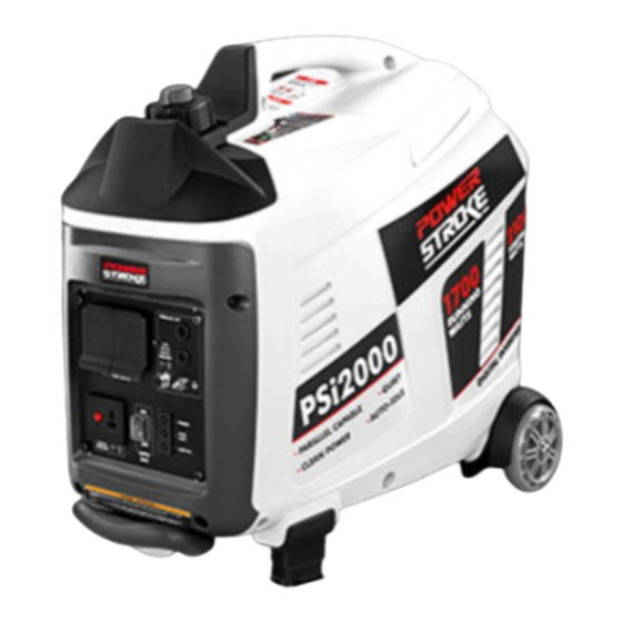
DIGITAL INVERTER GENERATOR
NOTICE
AVISO
Instrucciones de seguridad importantes .............................. 3-4
Reglas de seguridad específicas .............................................4
Símbolos .............................................................................. 5-7
Aspectos eléctricos .............................................................. 8-9
Características ................................................................. 10-11
Armado ...................................................................................11
Funcionamiento ................................................................ 12-15
Mantenimiento .................................................................. 15-18
Accessorios ............................................................................19
Corrección de problemas .......................................................19
Garantía ............................................................................ 20-21
Pedidos de piezas / servicio ...............................Pág. posterior
usuario debe leer y comprender el manual del operador antes
de usar este producto.
MANUAL DEL OPERADOR
GENERADOR DEL INVERSOR
ÍNDICE DE CONTENIDO
Para reducir el riesgo de lesiones, el
GUARDE ESTE MANUAL
PARA FUTURAS CONSULTAS
DE DIGITACES
PSi2000B
Advertisement
Table of Contents

Related Manuals for Power Stroke PSi2000B


Summary of Contents for Power Stroke PSi2000B
-
Page 1: Table Of Contents
OPERATOR’S MANUAL MANUAL DEL OPERADOR DIGITAL INVERTER GENERATOR GENERADOR DEL INVERSOR DE DIGITACES PSi2000B CUSTOMER SERVICE SERVICIO AL CLIENTE USA: 1-877-617-3501 Mexico: 01 800 843 1111 www.powerstroketools.com NEUTRAL FLOATING NEUTRAL DE FLOTACIÓN NOTICE AVISO Do not use E15 or E85 fuel in this product. It is a violation of federal law and will damage the unit and void your warranty. - Page 2 See this fold-out section for all of the figures referenced in the operator’s manual. Consulte esta sección desplegable para ver todas las figuras a las que se hace referencia en el manual del operador.
- Page 3 Fig. 1 G - Ground terminal (terminal de conexión a N - Power indicator (indicador de potencia) A - On/off switch/fuel valve (interruptor tierra) O - Auto idle switch (interruptor de ralentí de encendido y apagado/ interruptor encendido apagado/válvula H - Retractable handle (mango retráctil) automático) combustible) I - Battery charging cable (cable para cargar la...
- Page 4 Fig. 5 Fig. 10 Fig. 7 A - Starter grip and rope (mango del arrancador y cuerda) Fig. 8 A - On/off switch/fuel valve (interruptor de encendido y apagado/ interruptor Fig. 11 encendido apagado/válvula combustible) B - Off (apagado) C - On (encendido) Fig.
- Page 5 Fig. 13 Fig. 15 Fig. 17 A - Carburetor drain screw (tornillo de drenaje A - Screws (tornillos) del caburador) B - Muffler outlet (recubrimiento del silenciador) A - Oil cap/dipstick (tapa de relleno de aceite/ C - Spark arrestor (parachispas) Fig.
- Page 6 To register your PowerStroke product, please visit: www.powerstroketools.com LOCATE GENERATOR AT LEAST 20 FT.* AWAY TO REDUCE THE RISK OF CARBON MONOXIDE GETTING INSIDE THE HOME * Minimum distance as recommended by U.S. Department of Health and Human Services Centers for Disease Control and Prevention (www.cdc.gov/co). Your specific home and/or wind conditions may require additional distance.
-
Page 7: Important Safety Instructions
IMPORTANT SAFETY INSTRUCTIONS Do not start or operate the engine in a confined space, building, near open windows, or in other unventilated space DANGER: where dangerous carbon monoxide fumes can collect. Carbon Monoxide. Using a generator indoors CAN KILL Carbon monoxide, a colorless, odorless, and extremely YOU IN MINUTES. -
Page 8: Specific Safety Rules
IMPORTANT SAFETY INSTRUCTIONS or stressing the generator components, possibly leading to follow maintenance instructions may create a risk of to generator failure. shock or injury. Use only recommended or equivalent replacement parts Maintain the unit per maintenance instructions in this and accessories and follow instructions in the Maintenance Operator’s Manual. -
Page 9: Symbols
SYMBOLS The following signal words and meanings are intended to explain the levels of risk associated with this product. SYMBOL SIGNAL MEANING Indicates an imminently hazardous situation, which, if not avoided, will result DANGER: in death or serious injury. Indicates a potentially hazardous situation, which, if not avoided, could result WARNING: in death or serious injury. - Page 10 SYMBOLS Some of the following symbols may be used on this product. Please study them and learn their meaning. Proper interpretation of these symbols will allow you to operate the product better and safer. SYMBOL NAME DESIGNATION/EXPLANATION Volts Voltage Amperes Current Hertz Frequency (cycles per second)
- Page 11 SYMBOLS FUEL CAP WARNING DANGER PELIGRO Never remove fuel cap when unit is running. RISQUE D'INCENDIE ET DE BLESSURES GRAVES : Ne jamais retirer le capuchon du réservoir d'essence pendant que l'appareil fonctionne. Shut off engine and allow the unit to cool at least Éteindre le moteur et laisser refroidir l'appareil pendant au moins cinq minutes.
-
Page 12: Electrical
ELECTRICAL EXTENSION CORD CABLE SIZE Refer to the table below to ensure the cable size of the extension cords you use are capable of carrying the required load. Inadequate size cables can cause a voltage drop, which can damage the appliance and overheat the cord. Load in Watts Maximum Allowable Cord Length Current in... - Page 13 ELECTRICAL GENERATOR CAPACITY 2. Plug in and turn on the first load, preferably the largest load you have. Make sure the generator can supply enough continuous (run- 3. Permit the generator output to stabilize (engine runs ning) and surge (starting) watts for the items you will power smoothly and attached device operates properly).
-
Page 14: Features
FEATURES PRODUCT SPECIFICATIONS ENGINE GENERATOR Engine Type ..... Single Overhead Cam (SOHC), 106cc Rated Voltage .........120 V AC/12 V DC Replacement Spark Plug ... NHSP LD A7RTC or equivalent Rated Amps ..........14.2 A AC/7.5 A DC Rated Running Watts ..........1,700 W Cooling System ...........Forced Air Starting Watts ............ -
Page 15: Assembly
FEATURES ON/OFF SWITCH/FUEL VALVE RESET BUTTON The on/off switch/fuel valve is used in combination with the The reset button is used to restore power if an overload starter grip and rope to start the generator. It is also used occurs. To restore power, depress the reset button. to turn the generator off. -
Page 16: Operation
OPERATION NOTICE: DANGER: The spark arrestor on this product has not been evaluated Carbon Monoxide. Using a generator indoors CAN KILL by the USDA Forest Service and cannot be used on U.S. YOU IN MINUTES. forest lands. In addition, product users must comply Generator exhaust contains high levels of carbon with Federal, State, and local fire prevention regulations. - Page 17 OPERATION the generator, remove all loads from the generator and turn Mix fuel stabilizer and gasoline prior to filling the tank the generator off. Restart the unit and add loads back to by using a gas can or other approved fuel container and shaking gently to combine.
- Page 18 OPERATION STOPPING THE ENGINE WARNING: See Figure 5. Always shut off engine before fueling. Never remove Remove any load from the generator. fuel cap or add fuel to a machine with a running or hot Put the on/off switch/fuel valve in the OFF ( O ) position. engine.
-
Page 19: Maintenance
OPERATION MOVING THE GENERATOR Connect the battery charging cable assembly to the 12 V DC receptacle. See Figure 10. Start the generator. Turn off the generator. NOTE: The AC receptacles can be used while the DC Allow 30 minutes of “cool down” time before storing the receptacle is in use. - Page 20 MAINTENANCE Clean air vents with low pressure air that does not exceed SPARK PLUG MAINTENANCE 25 psi. See Figure 14. Wipe the exterior surfaces of the generator with a damp The spark plug must be properly gapped and free of deposits cloth.
- Page 21 MAINTENANCE The spark arrestor must be cleaned or replaced every 50 Tilt the generator and allow fuel to drain from the fuel tank hours or yearly to ensure proper performance of your product. into an approved container. Spark arrestors may be in different locations depending on ...
- Page 22 MAINTENANCE STORAGE When preparing the generator for storage, allow the unit to cool for 30 minutes then follow the guidelines below. STORAGE TIME PRIOR TO STORING Less than 2 months Drain gasoline from tank and dispose of in a suitable container according to state and local ordinances. 2 months to 1 year Drain fuel from carburetor.
-
Page 23: Accessories
ACCESSORIES The following recommended accessory is available and for use on this unit only: AUN9230PK Positive parallel kit terminal WARNING: Current attachments and accessories available for use with this tool are listed above. Do not use any attachments or accessories not recommended by the manufacturer of this tool. -
Page 24: Warranty
WARRANTY LIMITED WARRANTY WARRANTY COVERAGE OWT Industries, Inc., (the Company) warrants to the original retail purchaser that this PowerStroke Product is free from defects in material and workmanship and agrees to repair or replace, at the Company’s sole discretion, any defective Product free of charge within these time periods from the date of purchase: Two years, if the Product is used solely for personal, family, or household use;... - Page 25 WARRANTY LIMITED ENGINE WARRANTY OWT Industries, Inc., (the Company), warrants that each 4. Broken or scored parts caused by low oil level, dirty, new engine sold by it will be free, under normal use and or improper grade of oil. service, from defects in material and workmanship for a 5.
- Page 26 NOTES / NOTAS Page / Pàgina 22...
- Page 27 Para registrar su producto de PowerStroke, por favor visita: www.powerstroketools.com UBIQUE EL GENERADOR A UNA DISTANCIA DE POR LO MENOS 6 M (20 PIES)* PARA REDUCIR EL RIESGO DE QUE EL MONÓXIDO DE CARBONO INGRESE EN LA CASA Distancia mínima recomendada por el Departamento de Salud y Servicios Humanos y por los Centros para el Control y la Prevención de Enfermedades de los Estados Unidos (www.cdc.gov/co).
-
Page 28: Instrucciones De Seguridad Importantes
INSTRUCCIONES DE SEGURIDAD IMPORTANTES No haga arrancar o funcionar el motor en un espacio confinado, de edificio, cerca de ventana abiertas, o en otro área sin ventilación PELIGRO: donde se puedan recolectar las emanaciones de monóxido de carbono. El monóxido de carbono, un gas incoloro, inodoro y Monóxido de carbono. -
Page 29: Reglas De Seguridad Específicas
INSTRUCCIONES DE SEGURIDAD IMPORTANTES Los generadores fijos instalados de manera permanente son la Mantenimiento de este manual. El empleo de piezas diferentes o mejor alternativa para abastecer de electricidad al hogar durante el incumplimiento de las instrucciones de mantenimiento puede los cortes de energía. -
Page 30: Símbolos
SÍMBOLOS Las siguientes palabras de señalización y sus significados tienen el objeto de explicar los niveles de riesgo relacionados con este producto. SÍMBOLO SEÑAL SIGNIFICADO Indica una situación peligrosa inminente, la cual, si no se evita, causará PELIGRO: la muerte o lesiones serias. Indica una situación peligrosa posible, la cual, si no se evita, podría causar ADVERTENCIA: la muerte o lesiones serias. - Page 31 SÍMBOLOS Es posible que se empleen en este producto algunos de los siguientes símbolos. Le suplicamos estudiarlos y aprender su significado. Una correcta interpretación de estos símbolos le permitirá utilizar mejor y de manera más segura el producto. SÍMBOLO NOMBRE DENOMINACIÓN / EXPLICACIÓN Voltios Voltaje...
- Page 32 SÍMBOLOS ADVERTENCIA PARA LA TAPA DEL TANQUE DE DANGER PELIGRO COMBUSTIBLE RISQUE D'INCENDIE ET DE BLESSURES GRAVES : Ne jamais retirer le capuchon du réservoir d'essence pendant que l'appareil fonctionne. Nunca retire la tapa de combustible mientras esté Éteindre le moteur et laisser refroidir l'appareil pendant au moins cinq minutes.
-
Page 33: Aspectos Eléctricos
ASPECTOS ELÉCTRICOS CALIBRE DEL CORDÓN DE EXTENSIÓN Consulte el cuadro mostrado abajo para asegurarse de que el calibre de los cordones de extensión que utilice puedan con la carga eléctrica requerida. Los cordones de calibre insuficiente pueden causar una caída de voltaje, lo cual puede quemar el dispositivo y recalentar el cordón mismo. - Page 34 ASPECTOS ELÉCTRICOS CAPACIDAD DEL GENERADOR 2. Enchufe y active la primera carga, preferiblemente la máxima carga que tenga. Cerciórese que el generador pueda suministrar suficientes 3. Deje que se estabilice la salida del generador (el motor vatios de potencia continua (en marcha) y de sobrecorriente marcha uniformemente y el dispositivo acoplado funciona (al arrancar) para los equipos que desee alimentar al mismo correctamente).
-
Page 35: Características
CARACTERÍSTICAS ESPECIFICACIONES DEL PRODUCTO GENERADOR MOTOR Voltaje nominal ........120 V C.A/12 V C.C. Tipo de motor ....Leva única elevada (SOHC), 106cc Amperaje nominal......14,2 A C.A/7,5 A C.C. Bujía de repuesto ..... NHSP LD A7RTC o equivalente Potencia en marcha ..........1 700 W Sistema de enfriamiento........ -
Page 36: Armado
CARACTERÍSTICAS TAPA DE ACEITE/VARILLA PARA MEDIR EL NOTA: Lea y comprenda las instrucciones del juego paralelas antes del uso. Este juego es para el uso con esta unidad sólo. ACEITE Retire la tapa de aceite/varilla para medir el aceite para revisar BOTÓN DE REAJUSTE el nivel y añadir lubricante al motor cuando sea necesario. -
Page 37: Funcionamiento
FUNCIONAMIENTO AVISO: PELIGRO: El parachispas que acompaña a este producto no ha sido Monóxido de carbono. Usar un generador en el interior LO evaluado por el Servicio Forestal del Departamento de MATARÁ EN POCOS MINUTOS. Agricultura de EE. UU. y no se puede usar en terrenos Los gases de escape del generador contienen niveles altos forestales de EE. - Page 38 FUNCIONAMIENTO Rearranque de la unidad y agregue cargas atrás al generador NOTA: Para controlar la cantidad de estabilizador de combustible teniendo de uno en uno cuidado para no exceder la valores de que se agrega al motor, siempre mézclelo con la gasolina antes potencias de generadores.
- Page 39 FUNCIONAMIENTO Permita que el motor funcione 15-30 segundos y, después, desplace izquierda la palanca del anegador en la posición RUN ADVERTENCIA: (FUNCIONAMIENTO). Apague siempre el motor antes de reabastecer combustible. NOTA: Si desea que la máquina funcione más silenciosa y Nunca retire la tapa de combustible ni agregue combustible eficientemente, lleve el interruptor de ralentí...
-
Page 40: Mantenimiento
FUNCIONAMIENTO TRASLADO EL GENERADOR NOTA: Teniendo cuidado de no causar cortocircuito en las terminales. Un cortocircuito al juntar las terminales puede causar Vea la figura 10. chispas, daños a la batería o al generador y hasta quemaduras Apague la generador. o explosiones. - Page 41 MANTENIMIENTO REVISIÓN Y LIMPIEZA DEL FILTRO DE AIRE MANTENIMIENTO DE LA BUJÍA Vea las figuras 11 y 12. Vea la figura 14. Para obtener un desempeño apropiado y una larga vida útil de la La bujía debe tener el debido espacio interelectródico y debe estar unidad, mantenga limpios los filtro de aire.
- Page 42 MANTENIMIENTO Es necesario limpiar o reemplazar el parachispas cada 50 horas o DRENAJE DEL CARBURADOR anualmente para asegurarse del buen funcionamiento de la unidad. Apague la generador. Los parachispas pueden estar instalados en diferentes posiciones Retire el tornillo de la parte superior de la cubierta del motor. dependiendo del modelo del cual se trate.
- Page 43 MANTENIMIENTO ALMACENAMIENTO Al preparar el generador para guardarlo, deje que la unidad se enfríe durante 30 minutos y luego siga los lineamientos señalados abajo. TIEMPO DE ANTES DE GUARDARLO ALMACENAMIENTO Menos de dos meses Vacíe el tanque de combustible y colóquelo en un recipiente apropiado según lo establecido por las disposiciones estatales y locales.
-
Page 44: Accessorios
ACCESORIOS Los siguientes accesorios recomendados se encuentran y para el uso en esta unidad sólo: AUN9230PK Terminal positiva de juego paralelor ADVERTENCIA: Arriba se señalan los aditamentos y accesorios disponibles para usarse con esta herramienta. No utilice ningún aditamento o accesorio no recomendado por el fabricante de esta herramienta. -
Page 45: Garantía
GARANTÍA GARANTIA LIMITADA COBERTURA DE LA GARANTÍA OWT Industries, Inc., (la Compañía) garantiza al comprador minorista original que este Producto PowerStroke carece de defectos en material y mano de obra, y acuerda reparar o reemplazar, a la entera discreción de la Compañía, cualquier Producto defectuoso sin cargo en los siguientes períodos a partir de la fecha de la compra: Dos años si el Producto se utiliza exclusivamente para fines personales, familiares o domésticos. - Page 46 GARANTÍA DECLARACIÓN DE GARANTÍA LIMITADA AL MOTOR OWT Industries, Inc., (la Compañía), garantiza al válvulas, el carburador u otros componentes internos). comprador minorista original que cada motor nuevo que 4 Piezas rotas o rayadas debido a un bajo nivel de se venda carecerá...
- Page 47 NOTES...
-
Page 48: Advertencia
DIGITAL INVERTER GENERATOR GENERADOR DEL INVERSOR DE DIGITACES PSi2000B OPERATOR’S MANUAL MANUAL DEL OPERADOR CALIFORNIA PROPOSITION 65 SERVICE WARNING: For parts or service, contact your service dealer. Be sure to provide all relevant information when you call or visit. Please call 1-877-617-3501 for assistance.
Need help?
Do you have a question about the PSi2000B and is the answer not in the manual?
Questions and answers