Table of Contents
Advertisement
Available languages
Available languages
Quick Links
CUSTOMER SERVICE
SERVICIO AL CLIENTE
USA: 1-877-617-3501
Mexico: 01 800 843 1111
www.powerstroketools.com
NEUTRAL FLOATING
PUNTO NEUTRO FLOTANTE
Do not use E15 or E85 fuel in this product. It is a violation of federal law and will damage the unit
and void your warranty. Only use unleaded gasoline containing up to 10% ethanol.
No utilice combustibles E15 o E85 con este producto. Esto constituye una violación a la ley
federal, dañará la unidad y anulará la garantía. Utilice únicamente gasolina sin plomo que contiene hasta 10% de etanol.
TABLE OF CONTENTS
Important Safety Instructions ...............................................3-4
Specific Safety Rules .............................................................. 4
Symbols ...............................................................................5-7
Electrical ..............................................................................8-9
Features ................................................................................ 10
Assembly .........................................................................11-12
Operation .........................................................................13-15
Maintenance ....................................................................16-18
Troubleshooting .................................................................... 19
Warranty ...........................................................................20-21
Parts Ordering / Service ...........................................Back Page
WARNING:
To reduce the risk of injury, the user must
read and understand the operator's manual before using this
product.
SAVE THIS MANUAL FOR
FUTURE REFERENCE
OPERATOR'S MANUAL
NOTICE
AVISO
Instrucciones de seguridad importantes .............................. 3-4
Reglas de seguridad específicas .............................................4
Símbolos .............................................................................. 5-7
Aspectos eléctricos .............................................................. 8-9
Características .......................................................................10
Armado ............................................................................. 11-12
Funcionamiento ................................................................ 13-15
Mantenimiento .................................................................. 16-18
Corrección de problemas .......................................................19
Garantía ............................................................................ 20-21
Pedidos de piezas / servicio ...............................Pág. posterior
usuario debe leer y comprender el manual del operador antes
de usar este producto.
MANUAL DEL OPERADOR
3,250 WATT GENERATOR
GENERADOR 3 250 WATTS
ÍNDICE DE CONTENIDO
Para reducir el riesgo de lesiones, el
GUARDE ESTE MANUAL
PARA FUTURAS CONSULTAS
PS903250
Advertisement
Table of Contents

Related Manuals for Power Stroke PS903250


Summary of Contents for Power Stroke PS903250
-
Page 1: Table Of Contents
OPERATOR’S MANUAL MANUAL DEL OPERADOR 3,250 WATT GENERATOR GENERADOR 3 250 WATTS PS903250 CUSTOMER SERVICE SERVICIO AL CLIENTE USA: 1-877-617-3501 Mexico: 01 800 843 1111 www.powerstroketools.com NEUTRAL FLOATING PUNTO NEUTRO FLOTANTE NOTICE AVISO Do not use E15 or E85 fuel in this product. It is a violation of federal law and will damage the unit and void your warranty. - Page 2 See this fold-out section for all of the figures referenced in the operator’s manual. Consulte esta sección desplegable para ver todas las figuras a las que se hace referencia en el manual del operador.
- Page 3 Fig. 1 G - Oil drain plug (perno de drenaje de aceite) A - Analog hour meter (horómetro analógico) M - Ground terminal (terminal de conexión a B - Fuel cap (tapa del tanque de combustible) H - Stop switch (interruptor del apagado) tierra) C - Fuel tank (tanque de combustible) I - Recoil starter grip (mango del arrancador...
- Page 4 Fig. 4 Fig. 7 Fig. 10 A - Fuel valve (válvula de combustible) B - Recoil starter grip (mango del arrancador retráctil) A - Frame support with feet (apoyo del bastidor con pie) Fig. 11 B - Bolt (perno) Fig. 5 A - Handle bracket (abrazadera del mango) B - Handle (mango) C - Hole (agujero)
- Page 5 Fig. 13 Fig. 16 Fig. 18 Fig. 14 A - Spark plug (bujía) B - Spark plug cap (tapa de la bujía) Fig. 17 A - Fuel line (conducto de combustible) B - Petcock (llave de purga) C - Fuel valve (válvula de combustible) Fig.
- Page 6 To register your PowerStroke product, please visit: www.powerstroketools.com LOCATE GENERATOR AT LEAST 20 FT.* AWAY TO REDUCE THE RISK OF CARBON MONOXIDE GETTING INSIDE THE HOME * Minimum distance as recommended by U.S. Department of Health and Human Services Centers for Disease Control and Prevention (www.cdc.gov/co). Your specific home and/or wind conditions may require additional distance.
-
Page 7: Important Safety Instructions
IMPORTANT SAFETY INSTRUCTIONS Do not start or operate the engine in a confined space, building, near open windows, or in other unventilated DANGER: space where dangerous carbon monoxide fumes can Carbon Monoxide. Using a generator indoors CAN KILL collect. Carbon monoxide, a colorless, odorless, and YOU IN MINUTES. -
Page 8: Specific Safety Rules
IMPORTANT SAFETY INSTRUCTIONS Use only recommended or equivalent replacement parts Maintain the unit per maintenance instructions in this and accessories and follow instructions in the Maintenance Operator’s Manual. section of this manual. Use of any other parts or failure Inspect the unit before each use for loose fasteners, fuel to follow maintenance instructions may create a risk of leaks, etc. -
Page 9: Symbols
SYMBOLS The following signal words and meanings are intended to explain the levels of risk associated with this product. SYMBOL SIGNAL MEANING Indicates an imminently hazardous situation, which, if not avoided, will result DANGER: in death or serious injury. Indicates a potentially hazardous situation, which, if not avoided, could result WARNING: in death or serious injury. - Page 10 SYMBOLS Some of the following symbols may be used on this product. Please study them and learn their meaning. Proper interpretation of these symbols will allow you to operate the product better and safer. SYMBOL NAME DESIGNATION/EXPLANATION Amperes Current Hertz Frequency (cycles per second) Watt Power...
- Page 11 SYMBOLS FUEL WARNING No smoking when filling with gasoline. Do not overfill. Full level is 1 in. below the top of the fuel neck. Stop the engine for five minutes before refueling to avoid the heat from the muffler igniting fuel vapors. ENGINE LUBRICANT WARNING You must add lubricant before first operating the generator.
-
Page 12: Electrical
ELECTRICAL EXTENSION CORD CABLE SIZE Refer to the table below to ensure the cable size of the extension cords you use are capable of carrying the required load. Inadequate size cables can cause a voltage drop, which can burn out the appliance and overheat the cord. Load in Watts Maximum Allowable Cord Length Current in... - Page 13 ELECTRICAL GENERATOR CAPACITY POWER MANAGEMENT To prolong the life of the generator and attached devices, Make sure the generator can supply enough continuous it is important to take care when adding electrical loads to (running) and surge (starting) watts for the items you will power at the same time.
-
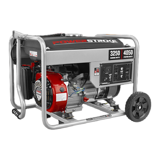
Page 14: Features
FEATURES PRODUCT SPECIFICATIONS ENGINE Rated Starting Watts ..........4,050 W Engine Type ............212cc OHV Rated Frequency ............60 Hz Fuel Volume ..............4 gal. DIMENSIONS Spark Plug ........Torch F6TC or equivalent Length ..............23.3 in. Engine Lubricant Volume........... 18 oz. Width ............... 18.3 in. GENERATOR Height .............. -
Page 15: Assembly
ASSEMBLY LOOSE PARTS LIST UNPACKING See Figure 2 This product requires assembly. The following items are included with the generator: Carefully cut the box down the sides then remove the machine and any accessories from the box. Make sure Description Qty. - Page 16 ASSEMBLY INSTALLING THE HANDLE BRACKET INSTALLING THE WHEELS See Figure 5. See Figure 6. Wheels are provided to assist in moving the generator to the Locate the following items: desired location and should be installed on the side opposite Handle bracket the recoil starter.
-
Page 17: Operation
OPERATION NOTICE: DANGER: This product is equipped with a spark arrestor that has Carbon Monoxide. Using a generator indoors CAN KILL been evaluated by the USDA Forest Service; however, YOU IN MINUTES. product users must comply with Federal, State, and Generator exhaust contains high levels of carbon local fire prevention regulations. - Page 18 OPERATION CHECKING/ADDING FUEL CHECKING/ADDING LUBRICANT See Figure 9. See Figure 8. NOTICE: DANGER: Attempting to start the engine before it has been properly Risk of fire and serious burns: Never remove fuel cap filled with lubricant will result in equipment failure. when unit is running.
- Page 19 OPERATION MOVING THE GENERATOR STARTING THE ENGINE See Figures 10 - 11. See Figure 13. Turn off the generator. NOTICE: Disconnect any equipment that is plugged into the On a level surface with the engine off, check the lubricant generator.
-
Page 20: Maintenance
MAINTENANCE Release latch on top of air filter cover. Remove cover and Normal maintenance, replacement or repair of emission con- set aside. trol devices and systems may be performed by any qualified repair establishment or individual with original or equivalent Remove the air filter. - Page 21 MAINTENANCE DRAINING FUEL TANK/CARBURETOR Tighten with wrench to compress washer. If spark plug is new, use 1/2 turn to compress washer appropriate See Figures 18 - 19. amount. If reusing old spark plug, use 1/8 to 1/4 turn for To help prevent gum deposits in the fuel system, drain the proper washer compression.
- Page 22 MAINTENANCE STORAGE When preparing the generator for storage, allow the unit to cool for 30 minutes then follow the guidelines below. STORAGE TIME PRIOR TO STORING Less than 2 months Drain gasoline from tank and dispose of in a suitable container according to state and local ordinances. 2 months to 1 year Drain fuel from carburetor.
-
Page 23: Troubleshooting
TROUBLESHOOTING PROBLEM POSSIBLE CAUSE SOLUTION Engine will not start. No fuel. Fill fuel tank. Stale gasoline or water in gasoline. Drain entire system and refill with fresh fuel. Lubricant level is low. Engine is equipped with Low Oil Shutoff. If engine lubricant level is low, it must be filled before unit will start. -
Page 24: Warranty
WARRANTY LIMITED NON-ENGINE WARRANTY STATEMENT OWT Industries, Inc., (the Company) warrants to the original retail purchaser that this PowerStroke Product is free from defects in material and workmanship and agrees to repair or replace, at the Company’s discretion, any defective Product free of charge within these time periods from the date of purchase: Three years, if the Product is used solely for personal, family, or household use;... - Page 25 WARRANTY LIMITED ENGINE WARRANTY UNITED POWER EQUIPMENT CO., LTD., warrants that 5. Broken or scored parts caused by low lubricant level, each new engine sold by it will be free, under normal use dirty, or improper grade of lubricant. and service, from defects in material and workmanship for a 6.
- Page 26 NOTES Page 22 — English...
- Page 27 Para registrar su producto de PowerStroke, por favor visita: www.powerstroketools.com UBIQUE EL GENERADOR A UNA DISTANCIA DE POR LO MENOS 6 M (20 PIES)* PARA REDUCIR EL RIESGO DE QUE EL MONÓXIDO DE CARBONO INGRESE EN LA CASA Distancia mínima recomendada por el Departamento de Salud y Servicios Humanos y por los Centros para el Control y la Prevención de Enfermedades de los Estados Unidos (www.cdc.gov/co).
-
Page 28: Instrucciones De Seguridad Importantes
INSTRUCCIONES DE SEGURIDAD IMPORTANTES No haga arrancar o funcionar el motor en un espacio confinado, de edificio, cerca de ventana abiertas, o en PELIGRO: otro área sin ventilación donde se puedan recolectar las Monóxido de carbono. Usar un generador en el interior LO emanaciones de monóxido de carbono. -
Page 29: Reglas De Seguridad Específicas
INSTRUCCIONES DE SEGURIDAD IMPORTANTES Los generadores fijos instalados de manera permanente sección de Mantenimiento de este manual. El empleo de son la mejor alternativa para abastecer de electricidad al piezas diferentes o el incumplimiento de las instrucciones hogar durante los cortes de energía. Incluso los generadores de mantenimiento puede significar un riesgo de descarga portátiles que están conectados correctamente pueden eléctrica o de lesiones. -
Page 30: Símbolos
SÍMBOLOS Las siguientes palabras de señalización y sus significados tienen el objeto de explicar los niveles de riesgo relacionados con este producto. SÍMBOLO SEÑAL SIGNIFICADO Indica una situación peligrosa inminente, la cual, si no se evita, causará lesiones PELIGRO: graves o mortales. Indica una situación peligrosa posible, la cual, si no se evita, podría causar lesiones ADVERTENCIA: graves o mortales. - Page 31 SÍMBOLOS Es posible que se empleen en este producto algunos de los siguientes símbolos. Le suplicamos estudiarlos y aprender su significado. Una correcta interpretación de estos símbolos le permitirá utilizar mejor y de manera más segura el producto. SÍMBOLO NOMBRE DESIGNACIÓN/EXPLICACIÓN Amperios Corriente...
- Page 32 SÍMBOLOS ADVERTENCIA DE COMBUSTIBLE No fume al abastecer el combustible. No llene de más. El nivel de lleno es 25 mm (1 pulg.) debajo del cuello del tanque de combustible. Pare la marcha del motor cinco minutos antes del reabastecimiento de combustible para evitar que el calor del silenciador encienda los vapores de combustible. ADVERTENCIA DEL LUBRICANTE DE MOTOR Antes de utilizar el generador debe...
-
Page 33: Aspectos Eléctricos
ASPECTOS ELÉCTRICOS CALIBRE DEL CORDÓN DE EXTENSIÓN Consulte el cuadro mostrado abajo para asegurarse de que el calibre de los cordones de extensión que utilice puedan con la carga eléctrica requerida. Los cordones de calibre insuficiente pueden causar una caída de voltaje, lo cual puede quemar el dispositivo y recalentar el cordón mismo. - Page 34 ASPECTOS ELÉCTRICOS CAPACIDAD DEL GENERADOR 1. Sin equipos conectados al generador, ponga en marcha el motor de la manera que se describe posteriormente en este Cerciórese que el generador pueda suministrar suficientes vatios manual. de potencia continua (en marcha) y de sobrecorriente (al arrancar) 2.
-
Page 35: Características
CARACTERÍSTICAS ESPECIFICACIONES DEL PRODUCTO MOTOR Potencia nominal en arranque en vatios ......4 050 W Tipo de motor ............212 cc OHV Frecuencia nominal ............60 Hz Volumen de combustible ........15,14 L (4 gal.) DIMENSIONES Bujía..........Torch F6TC o equivalentes Longitud ..........591,82 mm (23,3 pulg.) Volumen de aceite de motor ........ -
Page 36: Armado
ARMADO LISTA DE PIEZAS SUELTAS DESEMPAQUETADO Vea la figura 2. Este producto requiere armarse. Los siguientes artículos incluidos con generador: Orte cuidadosamente los lados de la caja y después Núm. retire la herramienta y cualesquier accesorios de la caja. ref. - Page 37 ARMADO INSTALACIÓN DE LAS RUEDAS INSTALACIÓN DEL ABRAZADERA DEL MANGO Vea la figura 5. Vea la figura 6. Las ruedas se proporcionan para ayudar a trasladar el Localice los siguientes artículos: generador hasta la ubicación deseada y deben instalarse Abrazadera del mango en el lado opuesto al arrancador retráctil.
-
Page 38: Funcionamiento
FUNCIONAMIENTO ADVERTENCIA: PELIGRO: No utilice ningún aditamento o accesorio no recomendado Monóxido de carbono. Usar un generador en el interior por el fabricante de este producto. El empleo de LO MATARÁ EN POCOS MINUTOS. aditamentos o accesorios no recomendados podría Los gases de escape del generador contienen niveles causar lesiones graves. - Page 39 FUNCIONAMIENTO En algunas áreas, se deben registrar los generadores en Coloque de nuevo la tapa del tanque de combustible y las respectivas compañías de servicios públicos locales. asegúrela. Si el generador es utilizado en una obra en construcción, Arranque el motor y déjelo funcionar por lo menos cinco es posible que se deban respetar reglamentaciones minutos para permitir que el estabilizador trate todo el...
- Page 40 FUNCIONAMIENTO APAGADO DEL MOTOR ADVERTENCIA: Vea la figura 12. Para apagar el motor en condiciones normales de Apague siempre el motor antes de reabastecer com- funcionamiento: bustible. Nunca retire la tapa de combustible ni agregue Desconecte del generador toda carga presente. combustible a una máquina mientras el motor esté...
-
Page 41: Mantenimiento
MANTENIMIENTO REVISIÓN Y REEMPLAZO DEL FILTRO DE AIRE Cualquier establecimiento o técnico de reparaciones Vea la figura 14. calificado puede realizar el mantenimiento normal, el reemplazo o la reparación de los dispositivos y sistemas Un filtro sucio puede causar dificultades de arranque, pérdida de control de emisiones, con repuestos originales o de rendimiento y acortar la vida útil del motor. - Page 42 MANTENIMIENTO DRENAJE DEL TANQUE DEL COMBUSTIBLE Y Retire la tapa de la bujía. DEL CARBURADOR Limpie toda la tierra presente alrededor de la base de la bujía. Vea las figuras 18 y 19. Retire los bujías con la llave (no incluido). Para evitar los depósitos de sustancias gomosas en el sistema de combustible, vacíe el tanque de combustible y Inspeccione la bujía para ver si está...
- Page 43 MANTENIMIENTO ALMACENAMIENTO Al preparar el generador para guardarlo, deje que la unidad se enfríe por durante 30 minutos y luego siga los lineamientos señalados abajo. TIEMPO DE ANTES DE GUARDARLO ALMACENAMIENTO Menos de dos meses Vacíe el tanque de combustible y colóquelo en un recipiente apropiado según lo establecido por las disposiciones estatales y locales.
-
Page 44: Corrección De Problemas
CORRECCIÓN DE PROBLEMAS PROBLEMA CAUSA POSIBLE SOLUCIÓN El motor no arranca. No hay combustible. Llene el tanque de combustible. Gasolina rancia o agua rancia en la Drene todo el sistema y reabastézcalo gasolina. con combustible nuevo. Está bajo el nivel de lubricante. El motor posee un apagado por poco aceite. -
Page 45: Garantía
GARANTÍA DECLARACIÓN DE GARANTÍA LIMITADA NO APLICABLE AL MOTOR OWT Industries, Inc., (la Compañía) garantiza al comprador minorista original que este Producto PowerStroke carece de defectos en material y mano de obra, y acuerda reparar o reemplazar, a la discreción de la Compañía, cualquier Producto defectuoso sin cargo en los siguientes períodos a partir de la fecha de la compra: Tres años si el Producto se utiliza exclusivamente para fines personales, familiares o domésticos. - Page 46 GARANTÍA GARANTÍA LIMITADA DE MOTOR UNITED POWER EQUIPMENT CO., LTD., garantiza que cada 4. El desgaste relacionado con la suciedad o mugre causado nuevo motor que venda estará, en condiciones de uso y por el mantenimiento insuficiente del filtro de aire (que a servicio normales, exento de defectos en materiales y mano menudo resulta en desgastes prematuros en el pistón, de obra durante el período indicado a continuación y a partir...
- Page 47 NOTAS Page 22 — Español...
-
Page 48: Advertencia
3,250 WATT GENERATOR GENERADOR 3 250 WATTS PS903250 OPERATOR’S MANUAL MANUAL DEL OPERADOR CALIFORNIA PROPOSITION 65 SERVICE For parts or service, contact your nearest service dealer. Be sure to provide WARNING: all relevant information when you call or visit. Please call 1-877-617-3501 for This product, its exhaust, and other sub- assistance.
Need help?
Do you have a question about the PS903250 and is the answer not in the manual?
Questions and answers