Table of Contents
Advertisement
Quick Links
Advertisement
Chapters
Table of Contents

Related Manuals for Atlantic Alfea Extensa A.I. R32 WOYA060KLT


Summary of Contents for Atlantic Alfea Extensa A.I. R32 WOYA060KLT
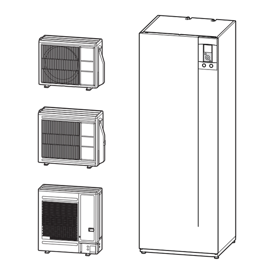
- Page 1 INSTALLATION Alfea Extensa A.I. R32 Air/water heat pump split 2 services Outdoor unit WOYA060KLT WOYA080KLT WOYA100KLT Hydraulic unit 024306 024307 024308 024309 U0671217_2114_EN_11 For professionals. 07/09/2022 To be kept by the user for future reference...
- Page 2 ■ Installation and maintenance rules ■ Containment of refrigeration circuits The appliance must be installed and maintained All refrigeration circuits are sensitive to dust and by an approved professional in accordance with moisture contamination. If any such pollutants current regulations and codes of practice. penetrate the refrigeration circuit, they can aff...
- Page 3 ■ Electrical connections • Connecting to screw terminals The use of ring, spade or blade terminals or Before performing any maintenance, make sure caps is prohibited. that all power supplies have been cut off . - Always select wire that complies with current •...
-
Page 4: Table Of Contents
This appliance must be installed by qualifi ed personnel holding a certifi cate of competence in the handling of refrigerants. Contents Description of the equipment Packing ....... . . 6 Operating Range . - Page 5 Maintenance of the installation Checking the hydraulic circuit ....70 Checking the refrigeration circuit ... . . 70 Maintenance of the DHW tank .
-
Page 6: Description Of The Equipment
Description of the equipment ► Packing Packing contents list Heat Pump Outdoor unit Hydraulic unit Model Export code Reference Code Reference Code Alféa Extensa Duo A.I. 3 R32 526158 Alféa Extensa Duo A.I. 3 R32 24306 Alféa Extensa Duo A.I. 5 R32 526159 WOYA060KLT 700227... - Page 7 ► General characteristics Model Rated heating performances (outdoor temp. / fl ow temp.) Heat output +7°C/+35°C - Underfl oor heating system 3,35 4.50 5.50 7.50 +7°C/+55 °C - Radiator 4.50 5.50 7.00 Power Input +7°C/+35°C - Underfl oor heating system 0,68 0.949 1.18...
- Page 8 ■ Outdoor Unit, models 3, 5, 6 ■ Outdoor Unit, model 8 ■ Outdoor Unit, model 10 fi g. 1 - Dimensions in mm - 8 - Alfea Extensa A.I. R32 / INSTALLATION / 2114 - EN...
- Page 9 ■ Hydraulic unit Back view Side view Front view Space requirements of the hydraulic unit, see fi g. 19, page 20. fi g. 2 - Dimensions in mm Heating inlet Ø 26x34 1” male Heating outlet Ø 26x34 1” male Domestic hot water Domestic cold water Ø...
- Page 10 mCE (1 mbar = 10 mmCE = 100 Pa) PWM 100% PWM 75% fi g. 4 - Available hydraulic pressures and fl ow rates Débit L/min Flow L/min Flow according to % PWM Débit en fonction du % PWM 100 % PWM fi...
- Page 11 Heat Pump return sensor. Heat Pump fl ow sensor. Outside sensor QAC34 32500 30000 27500 43907 25000 22500 10000 20000 17500 2490 15000 1000 12500 10000 7500 5000 ° C 2500 °C fi g. 6 - Ohmic sensor values (Hydraulic unit) 10000 - Compressor.
- Page 12 ► Description ■ Outdoor unit Model 3, 5 & 6 ■ Outdoor unit Model 8 ■ Outdoor unit Model 10 Key : High performance and low noise impeller. Noise and thermally insulated "Inverter" compressor. Electrical motor with variable "Inverter" operation. 10.
- Page 13 ■ Hydraulic unit Key : Electric control box. Drain valve. Sensors : Controller / User interface. 10. Safety valve. 20. Heat pump return sensor. Start/stop button. 11. Safety thermostat. 21. Domestic Hot Water sensor. Hydraulic unit circulation pump. 12. Pressure gauge. 22.
- Page 14 ► Operating principle The heat pump transmits the energy contained in the • Control functions surrounding air into the dwelling to be heated and for - The heating circuit's fl ow temperature is controlled by production of domestic hot water. the temperature control.
- Page 15 • Domestic hot water (DHW) operating principles Two domestic hot water (DHW) temperatures can be set: Comfort and ECO. The production of DHW takes priority over heating; The default DHW program is set to the Comfort Where there is simultaneous demand for DHW and temperature between 00:00 and 05:00 and between heating, the heat pump will regulate assigned time 14:30 and 17:00 and to the ECO temperature for the...
-
Page 16: Installation
Installation ► Installation of refrigeration connections Bend the pipes into position and make holes for them through the fl oor or walls either with their protective caps in place or after brazing. Keep the protective caps in place or ends brazed until the appliance is commissioned. -
Page 17: Installation Of The Outdoor Unit
► Installation of the outdoor unit ▼ Installation precautions • During normal operation, condensation is common. The outdoor unit must only be installed Ensure that the unit is installed in a well drained outside. If a shelter is required, it must have location (e.g. - Page 18 ■ Outdoor Unit, model 10 100 mm 1000 mm 150 mm 1500 mm 200 mm 3000 mm 250 mm 3500 mm 300 mm M = 300 mm max 500 mm N = 500 mm max 600 mm fi g. 17 - Minimum installation clearances around the outdoor unit (model 10) - 18 - Alfea Extensa A.I.
- Page 19 • The surface on which the appliance is installed must: - Be permeable (soil, gravel, etc.). - Be perfectly fl at, - Support its weight easily. - Allow a solid fastening base, - Not transmit any vibration to the dwelling. Anti-vibration blocks are available as an option.
- Page 20 ► Installation of the hydraulic unit Heat sources such as : - Open fl ame, - High temperature surface >700°C (fi lament), - unsealed contactor >5kVA, Avoid using sources of heat inside the room where the heat pump is installed. If this is not possible, page 24 ▼...
- Page 21 fi g. 20 - Open the front cover fi g. 21 - Removing the cover fi g. 22 - Floor fi xing Alfea Extensa A.I. R32 / INSTALLATION / 2114 - EN - 21 -...
- Page 22 ▼ Minimum room volume Model (kW) Refrigeration connections Length In accordance with EN 378-1 -2017 standard 3, 5, 6 (Refrigerating systems and heat pumps - Safety and R32 gas 1020 1630 environmental requirements), the ystem's hydraulic charge 15 m unit and all refrigeration connections passing through min room inhabited areas must comply with the minimum room volume...
- Page 23 200max fi g. 25 - Position of openings for ventilation Room volume (m Refrigerant Amount (g) Minimal section (S) of the opening (cm 970 500 1000 550 1100 600 No requirement 1170 600 1300 700 1400 750 1500 800 1600 850 1700 900 1800 950 1840 950...
- Page 24 ▼ With Heat sources Heat sources such as : - Open fl ame, - High temperature surface >700°C (fi lament), Model (kW) - unsealed contactor >5kVA, Refrigeration connections Length 3, 5, 6 In accordance with IEC 60-335-2-40 standard, the hydraulic module of the heat pump as well as all the R32 gas 1020 1630...
- Page 25 Min. room surface Surface minimum fi g. 27 Voir figure xx pxx Surface mini Min. room surface Room surface (A) Surface pièce (A) Surface pièce (A) > Surface mini ? Room surface (A) > Min. room surface ? Module hydraulique installé Indoor unit in an Pas de recommandation No requirement...
-
Page 26: Refrigeration Connections
Refrigeration connections This appliance uses refrigerant R32. • Other remarks Comply with the legislation on handling of refrigerants. - After each maintenance operation on the refrigeration circuit and before fi nal connection, take care to put ► Rules and precautions the caps back in position to avoid any pollution of the refrigeration circuit. -
Page 27: Shaping The Refrigeration Pipes
► Shaping the refrigeration pipes ▼ Bending fl are Flaring tool The refrigeration pipes must be shaped only on a bending machine or with a bending spring in order to avoid any risk of crushing or breaking them. Remove the insulation material from the section of Pipe pipe to be bent. - Page 28 3, 5 and 6 HP model liquid liquid liquid Outdoor unit connections 1/2" 1/4" 1/2" 1/4" Diameter: (D1) 1/2" (D2) 1/4" (D1) 1/2" (D2) 1/4" (D1) 5/8 (D2) 3/8 Minimum length (L) Refrigeration Maximum length* (L) 15 m 15 m 20 m connections Maximum length** (L)
- Page 29 ► Checks and connection ▼ Filling with gas ■ See Appendices page 76 The refrigeration circuit is very sensitive to dust and humidity: check that the area around the connection is clean and dry before removing the Indicate on the label present on the outdoor plugs protecting the refrigeration connectors.
- Page 30 ▼ Additional fi lling The amount needed to fi ll the outdoor units corresponds to the maximum distances between the outdoor unit and the hydraulic unit as defi ned here page 28. If the distances are greater, an additional amount of R32 is required. For each type of appliance, this additional amount depends on the distance between the outdoor unit and the hydraulic unit.
- Page 31 ▼ Recovering the refrigerant in the outdoor unit Before performing any maintenance, make sure that all power supplies have been cut off . Stored energy: after cutting off the power supplies, wait for 10 minutes before accessing the internal parts of the equipment. Perform the following procedures to collect the refrigerant.
-
Page 32: Hydraulic Connections
Hydraulic connections "Basic Hydraulic Layout", page 78 ► Heating circuit ▼ Flushing the installation Before connecting the hydraulic unit to the installation, rinse out the heating system correctly to eliminate any particles that may aff ect the appliance's correct operation. Do not use solvents or aromatic hydrocarbons (petrol, paraffi... -
Page 33: Dhw Circuit
▼ Volume of the heating system You must maintain the minimum installation water volume. If the required water volume is not available in the heating system a buff er tank must be installed on the return pipework of the heating circuit. Where the system is fi... -
Page 34: Electrical Connections
Electrical connections Before performing any maintenance, make sure that all power supplies have been cut off . Electrical installation must be performed in accordance with current regulations. The electrical diagram for the hydraulic unit is shown on fi g. 59, page Room sensor A78 (battery/option) Outside sensor Room sensor A59 (battery/option) -
Page 35: Cable Dimensions And Protection Rating
► Cable dimensions and protection rating These cable dimensions are provided for information purposes only and do not exempt the installer from checking that these dimensions match requirements and comply with current standards. • Outdoor Unit Power Supply Heat Pump (HP) Electricity supply 230 V - 50 Hz Max. -
Page 36: Outdoor Unit
► Outdoor unit Access to connection terminals: • Models 3, 5, 6 and 8 - Remove the cowl. • Model 10 - Remove the front panel. Avoid contact between cables and refrigeration valves / connections. Use cable clamps to prevent any power cables from being disconnected accidentally. - Page 37 ▼ Heating cable (optional) - Locate the heating part (see fi g. 42). - Place the thermostat at the bottom of the tank. - Run the bottom of the tank with the heating part of the cable (make sure that the drain hole is covered by the Thermostat Thermostat heating part).
-
Page 38: Hydraulic Unit
► Hydraulic unit ▼ Contract with Energy Supplier Access to connection terminals: - Remove the front plate. The heat pump can be set to operate with diff erent - Open the power control box. energy tariff s (eg off -peak, Solar photovoltaic (PV).In particular, domestic hot water (DHW) at the comfort - Make the connections according to the diagram (fi... - Page 39 ▼ External control It is possible to control the changeover from "Heating Mode" to "Cooling Mode" via an "external control unit". Function not compatible with : - Dual circuit kit - Room sensors A59, A75 et A78 Parameter setting HP confi guration Tariff...
- Page 40 Power supply terminal block HP controller Safety thermostat Power Relay for electric backup Cable grommets (sensors) Interface Board Terminal DHW Relay + Terminal Cable grommets (power) fi g. 44 - Description of the hydraulic module's electrical control box Hydraulic unit Outdoor unit 1 2 3 1 2 3 L N...
- Page 42 ► ► Outside sensor Room sensor (option) The outside sensor is required for correct operation of The room sensor is optional. the heat pump. Please see the fi tting instructions on the sensor’s Please see the fi tting instructions on the sensor’s packaging.
- Page 43 Power limitation or EDR (Energy Demand Reduction) Tariff s, peak times/off - peak times, PV External fault External component contact* (faults, power limiter, electricity meter) Outside sensor ** Typass ATL ** Room sensor A59 (if cabled) ** Room sensor A75 * If the control device does not provide a potential-free contact, the contact must be relayed to create an equivalent wiring.
-
Page 44: Controller Interface
Controller Interface ► User Interface 15:23 7 September 2017 15:23 7 September 2017 12° 12° 21,5 21.5 19.5 19,0° 19,0° 19,0° Zone 1 Zone 2 ME U ME U 1 heating Circuit version 2 heating circuit version + domestic hot water (DHW) + domestic hot water (DHW) Description Menu button... -
Page 45: Display Description
► Display Description 15:23 7 September 2017 12° 21.5 19.5 19,0° 19,0° Zone 1 Zone 2 Symbols Defi nitions Symbols Defi nitions Mode 15:23 Time Comfort Date 7 September 2017 Manual (Temporary temperature setpoint derogation) Temperature 21.5 measured by the room sensor* 19,0°... -
Page 46: Installer Menu
► Installer Menu To access the Installer Menu, press and hold the button and turn the knob a quarter turn to the right. To return to the User Menu, repeat the same operation. ME U fi g. 48 - Installer Menu ►... - Page 47 ► Modifying Settings • Turn the knob to highlight the setting you wish to change. MENU • Press the knob to accept the change. • Turn the knob to adjust the setting. Installed options • Press the knob to accept your choice. Hydraulic confi...
-
Page 48: Temperature Control
Temperature control The heat pump’s operation is subject to the temperature control. The heating circuit water temperature setpoint is adjusted according to the outdoor temperature. If there are thermostatic valves on the installation, these must be fully open or set higher than the normal temperature setpoint. - Page 49 Pente de la 2.75 Heating curve gradient courbe de chauffe ° C 2.25 Radiateur classique Standard radiator 1.75 Radiateur BT Low temperature radiator 1.25 (basse température) Application relève de chaudière With boiler connection Heat pump application only Application PAC seule Dynamic radiators Radiateur dynamique 0.75...
-
Page 50: Commissioning
Commissioning - Close the installation's main circuit breaker. - Press the heat pump's Start/Stop button. Upon initial start-up (or in winter), to preheat the To ensure that inputs EX1, EX2 and EX3 operate compressor, engage the installation's main circuit correctly: Check that the electricity supply's breaker (outdoor unit power supply) several neutral phase polarity has been respected. - Page 51 Easy Start 2nd circuit kit - If the installation covers 2 zones, set "2nd circuit kit" to "Yes". Easy Start Emitters type Area 1 (Direct circuit) - Choose the radiator type for each zone: Low temp. radiator / Heat. fl oor system / Dynamic Radiators / Radiators. Low temp.
-
Page 52: Controller Menu
Controller Menu ► Menu Structure Installed options page 53 Hydraulic confi guration Heating Control / Temperature control Temperature control page 53 Comfort optimisation ECO mode limitation Setting setpoint T° Time programming General Confi guration Time programming Setting setpoint T° Anti-legionella management HP confi... -
Page 53: Installed Options
Installed options ► Installed options Installed options are confi gured during commissioning (see page 50). However, you can modify them by accessing the "Installed Options" menu. Name of Appliance - Choose the appliance's power. Installed options Electrical backup Name of Appliance -- KW - Choose the electrical backup power. - Page 54 Hydraulic confi guration Area 1 Control / Temperature control Temperature control Choose the temperature control to adjust: "Heating". Two methods for adjusting the temperature control are available: fl ow temperature or gradient control. ● Control using fl ow temperature - Set "Room T° infl uence" then select "Advanced settings". - Set "Display"...
- Page 55 Hydraulic confi guration Area 1 Control / Temperature control Comfort optimisation Area 1 Comfort optimisation "Accelerated decrease": ON / Stop. Accelerated decrease Stop "ECO / Comfort switchover" Anticipates time needed to reach the comfort setpoint. Max anticipation "Comfort / ECO switchover" Anticipates time needed to switch from comfort setpoint ECO / Comfort switchover 03:00 h to ECO setpoint.
- Page 56 Hydraulic confi guration Area 1 Time programming - Choose "Heating" or "Cooling" as well as the appropriate zone by accessing the menu: "Programming" > "Heating" / "Cooling" > "Area 1" / "Area 2". - Select the day. - Adjust the Comfort period start and end times. If 2 or 3 Comfort periods are not required, click on "--:--".
- Page 57 Hydraulic confi guration Hot water ▼ Hot Water (HW) General Confi guration DHW Circuit Confi guration Comfort T° charge DHW program + off -peak hours "Comfort T° charge": DHW program + off -peak hours / Off -peak hours / Permanent. Electrical back-up power: 0.1 to 10 KW.
-
Page 58: Hp Confi Guration
HP confi guration ► HP Confi guration ▼ HP Compressor confi guration "Minimum shutdown time": 3 mins... 20 mins. Compressor confi guration "Pump speed": 70%... 100%. (fi g. 5, page "Post-circulation": 0 secs... 600 secs... Minimum shutdown time 8 mins "Power shedding operating": Automatic, When needed. - Page 59 HP confi guration Tariff input confi guration Heat Pump Tariff input confi guration Power shedding + Type of use "Type of use": Power shedding + Off -peak hours / Smartgrid / EXT control. Off-peak hours "EX1: function activation": 230V / 0V. EX1: function activation 230V "EX2: function activation": 230V / 0V.
-
Page 60: System Status
System status ► System status Active functions The "Active Functions" page tells you which services are operating and allows you to change their status. Active functions Indoor comfort Heating - "Indoor comfort": Heating / Cooling / Stop. Area 1 Start - "Area 1"... -
Page 61: Fault Diagnosis
System status Errors history Errors history 10/09/2016 Error Outside sensor, Flow sensor Flow sensor 10/09/2016 Error 44: Return sensor HP, 50: DHW sensor 1, 60: Room sensor 1, 65: Room sensor 2, 09/09/2016 Error 83: BSB short-circuit, 127: Legionella temp, 212: Internal comm failure, 369: External, 09/09/2016 Error 370:... -
Page 62: Auxiliary Functions
Auxiliary functions ► Auxiliary functions Floor drying - Choose the zone. - Choose the "Drying type": Stop / Automatic / Manual. • Automatic Drying Max fl ow T° Area 1 fl oor drying Drying type Stop Flow T° setpoint 25°C 18 1 Automatic Drying •... - Page 63 Auxiliary functions Relay test - "HP circulation pump": ON / ---- - "Elec. backup 1": ON / ---- Relay test - "Area 2 circulation pump": ON / ---- HP circulation pump ---- Elec. backup 1 ---- - "Mixing valve": Open / Close / ---- Area 2 circulation pump ---- - "DHW valve": DHW / ----...
-
Page 64: Settings
Settings ► Settings Date and time Settings Date and time Monday September 2016 To set the appliance's date and time, access the menu: "Settings" > "Date and Time". 09: 45 Summer / winter time Automatic Modify Validate Language Settings Language To set the appliance's language, access the menu: English "Settings"... - Page 65 Settings Advanced/simplifi ed menu Two display modes for menus and appliance functions are available: - Advanced menu: - The appliance follows the time programming defi ned in paragraph "Time programming", page - Simplifi ed menu*: - The appliance operates at a constant temperature set directly by the user. - Some functions are no longer accessible.
- Page 66 Settings Areas name Settings Circuits name You can customise the zone names from the menu: Rename Zone 1 in "Settings" > "Areas name". Area 1 Available names: "Area 1" / "Area 2" / "Day area" / "Night area" / "1st fl oor" / "Lounge" Rename Zone 2 in / "G.
- Page 67 Settings Software versions Software version HMI: xxxx xxxx xxxx xxxx Show the display and controller software versions. Controller: RVS21 - 85.002.030 Alfea Extensa A.I. R32 / INSTALLATION / 2114 - EN - 67 -...
-
Page 68: Easy Start
Easy Start ► Easy Start Easy Start - Turn the knob to choose the language. English - Press the knob to accept. Easy Start Monday September 2016 - Turn the knob to adjust the date. Press the knob to accept. - Repeat this operation for the month, year, hours and minutes. - Page 69 Easy Start Emitters type Area 1 (Direct circuit) - Choose the radiator type for each zone: Low temp. radiator / Heat. fl oor system / Dynamic Radiators / Radiators. Low temp. radiator Easy Start Cooling - If the installation is fi tted with cooling function, choose the zone(s): None / Area 1 / Area 2 / Area 1 and 2.
- Page 70 Fault Diagnosis 15:23 7 September 2017 12° --,- If a fault occurs, the error number appears on the welcome screen. 24,0° To obtain the error's designation, select it using the knob. Error XXX Error In the event of an error originating in the outdoor unit, the user interface displays error code "370: Thermodynamic Generator"...
- Page 71 ► Operation signals with the HP circulator LED Off The pump does not work, no electrical power. Green LED on The pump works normally Circulation pump operation in “alert” mode Green/Red LED blink (under unusual conditions such as: dry running, motor overload due to impurities in the water, etc.).
-
Page 72: Faults In The Outdoor Unit
► Faults in the outdoor unit ■ Hydraulic unit: Flashing of the diode visible on the interface board. Interface Board Error Error designation (models 3, 5, 6 and 8) Error designation (model 10) Green Serial communication error Combination Error UART communications error Hydraulic unit heat-exchange thermistor error Outdoor unit main PCB error Inverter error... - Page 73 ▼ Outdoor Unit : modèle 10 When an error occurs: - The LED "ERROR" (2) blinks. POWER PUMP PEAK ERROR - Press once on the switch "ENTER" (S132). DOWN NOISE MODE - The LED (L1 & L2) blinks several times depending on the error's type (see below).
-
Page 74: Maintenance Of The Installation
Maintenance of the installation Before performing any maintenance, make sure that all power supplies have been cut off . Stored energy: after cutting off the power supplies, wait for 10 minutes before accessing the internal parts of the equipment. ► Checking the hydraulic circuit If frequent refi... -
Page 75: Other Maintenance
Other maintenance ► Emptying the hydraulic unit Return from - Remove the front panel from the HP. the heating circuit - Place the distribution valve in the middle position. Valve motor - Open the drain valve (ref. 5). - Open the hydraulic unit's manual bleeder valve (ref. 6). Valve - Open the installation’s bleeder valve(s). -
Page 76: Appendices
Appendices ► Filling the installation with gas This operation is reserved for installers familiar with the legislation for handling refrigerants. Creating a vacuum with a calibrated vacuum pump is essential (see APPENDIX 1). Never use equipment used previously with any refrigerant other than a HFC. Only remove the refrigeration circuit caps when performing the refrigeration connections. - Page 77 ▼ Seal test ▼ Creating a vacuum - Remove the protective plug (B) from the fi lling hole The triple evacuation method (APPENDIX 2) (Schrader) in the gas valve (large diameter). is strongly recommended for any installation - Connect the high pressure hose from the Manifold to and especially when the outdoor temperature the fi...
-
Page 78: Basic Hydraulic Layout
► Basic Hydraulic Layout ■ 1 heating circuit - 78 - Alfea Extensa A.I. R32 / INSTALLATION / 2114 - EN... - Page 79 ■ 2 heating circuits Alfea Extensa A.I. R32 / INSTALLATION / 2114 - EN - 79 -...
-
Page 80: Electrical Cabling Plans
► Electrical Cabling Plans Before performing any maintenance, make sure that all power supplies have been cut off . Stored energy: after cutting off the power supplies, wait for 10 minutes before accessing the internal parts of the equipment. ▼ Outdoor unit Vanne 4 voies 4-way valve Electronic expansion... - Page 81 Colour codes BK Black BN Brown BU Blue GN Green GY Grey Capteur Pressure sensor Ventilateur Fan motor OG Orange de pression RD Red VT Violet WH White YE Yellow Compresseur Compressor R(U) T(W) S(V) Printed Circuit Board Carte inverter (Disply) Printed Circuit Board Carte de régulation...
- Page 82 ▼ Hydraulic unit Connections on the heat pump controller, accessories and options (see fi g. 46, page Connection to terminal blocks and power relay (see fi g. 46, page fi g. 59 - Electrical wiring of hydraulic unit (excluding connections made by installer) - 82 - Alfea Extensa A.I.
- Page 84 Quick-start procedure Before switching on the hydraulic unit: • Check the electric wiring. • Check the refrigeration circuit and make sure the it has been gassed. • Check the hydraulic circuit's pressure (1 to 2 bar), check that the heat pump has been bled, along with the rest of the installation.
- Page 85 ▼ Starting-up Not compliant Quick Start Procedure (see chapter " Commissioning", page 50). Close the installation's main circuit breaker (outdoor unit power supply) 6 hours before testing => Preheating of the compressor. Press the On/Off Switch => Initialisation takes several seconds. Operation of the heating circulation pump.
-
Page 86: Commissioning Technical Datasheet
► Commissioning technical datasheet Site Installer Serial No. Serial No. Outdoor unit Hydraulic unit Model Model Refrigerant type Refrigerant load Checks Operating voltage & current on outdoor unit Compliance with positioning distances Condensate evacuation correct Electric connections / connections tightness No GAS leaks (unit ID No.: Icomp Installation refrigeration connection correct (length... - Page 87 Instructions for the end user Explain to the user how his installation operates, in particular the functions of the room sensor and the programmes accessible to them via the user interface. Emphasise that a heated fl oor has signifi cant inertia and that therefore any adjustments must be made gradually.
- Page 88 Commissioning date: atlantic-comfort.com Société Industrielle de Chauffage Address of your heating installer or customer service. SATC - BP 64 - 59660 MERVILLE - FRANCE This equipment complies with: - Low Voltage Directive 2014/35/EC in accordance with NF EN 60335-1, NF EN 60335-2-40, NF EN 60529, NF EN 60529/A2 (IP) standards,...
Need help?
Do you have a question about the Alfea Extensa A.I. R32 WOYA060KLT and is the answer not in the manual?
Questions and answers