Table of Contents
Advertisement
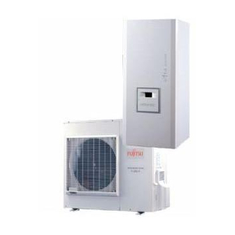
alféa S
Heat pump air/water
split single service
model S5
model S6
model S8
model S10
model S13
model S16
Document n° 1303-16 ~ 18/03/2011
FR
EN
IT
NL
ES
PT
Installation and
operating manual
intended for professionals
To be saved for
future consultation
www.atlantic.fr
Subject to modifications without notice.
Non contractual document.
DE
Advertisement
Table of Contents

Related Manuals for Atlantic alfea S S5


Summary of Contents for Atlantic alfea S S5
- Page 1 Heat pump air/water split single service model S5 model S6 model S8 model S10 Installation and operating manual intended for professionals To be saved for future consultation model S13 model S16 www.atlantic.fr Subject to modifications without notice. Non contractual document.
-
Page 2: Table Of Contents
Heat pump Alfea S " This device requires for its installation, the intervention of qualified personnel with a certificate of capacity for handling refrigerants. Contents Description of the unit ..........4 Package. - Page 3 Heat pump Alfea S Regulation system..........31 User interface and remote control (Option) .
-
Page 4: Description Of The Unit
Heat pump Alfea S Packing list Heat pump Outside unit Hydraulic module Designation Réf. Model Code Model Code Model S5 522604 AOYA18LALL 700718 MH-S5 023108 Model S6 522605 AOYA18LALL 700718 MH-S6 023109 Model S8 522606 AOYA24LALL 700724 MH-S8 023107 Model S10 522607 AOYA30LBTL 700730... -
Page 5: Specifications
Heat pump Alfea S Specifications Designation, model ..S5 ....S6 ....S8 ....S10 ..... S13 ....S16 Nominal heating performances (outside temperature/ initial temperature) Heat output +7 °C / +35 °C - Floor heating system kW..4,60 ....6,50 .....8,00 ....10,30 ... 13,70 .....16,20 -7 °C / +35 °C - Floor heating system kW.. -
Page 6: Heating Power Curve
Heat pump Alfea S Heating power curve Values according to standard EN 14511, for which it is necessary to add the power absorbed by the heating circulation pump. 6,00 Floor heating system 5,50 Heat output Very low temperature radiator 5,00 4,50 4,00 3,50... - Page 7 Heat pump Alfea S 12,00 11,00 Floor heating system 10,00 Heat output Very low temperature radiator 9,00 8,00 7,00 6,00 5,00 4,00 Power absorbed 3,00 2,00 1,00 Outside temperature (°C) 14,00 13,00 12,00 Heat output 11,00 10,00 9,00 8,00 Floor heating system 7,00 Very low temperature radiator 6,00...
- Page 8 Heat pump Alfea S " Outside unit, Model S5, S6, S8 Overflow hole (Ø 20) 4 Holes Ø 10) Sight of lower part 1/4” 1/4” 1/2” 5/8” Front view Side view Top view " Outside unit, Model S10 Overflow hole (Ø 20) Holes Ø...
- Page 9 Heat pump Alfea S " Outside unit, Model S13, S16 Overflow hole (Ø 20) Holes Ø 10) Sight of lower part 1290 3/8” 5/8” Front view Side view Top view Figure 2 - Dimensions in mm " Hydraulic module 1000 1034 Heating return Outside unit...
- Page 10 Heat pump Alfea S Outdoor sensor QAC34 1mbar = 10 mmCE = 100 Pa mbar 43907 10000 2490 1000 ° C Figure 4 - Hydraulic pressures and flow rates available Heat pump return sensor Heat pump flow sensor 32500 30000 27500 25000 22500...
-
Page 11: Description
Heat pump Alfea S Description " Model S5, S6, S8 " Model S13, S16 " Model S10 Legend : 1 - Low-noise, high-output coil. 2 - Electric variable speed "inverter" motor. 3 - "Inverter" control module. 4 - Vacuum start (pump down) and control light. 5 - Connection terminal blocks (power and interconnection). -
Page 12: Operating Principle
Heat pump Alfea S Legend : 1 - Electric box. 2 - Regulator / User interface. 3 - Start/stop switch. 4 - Heating circulation pump. 5 - Initial heating. 6 - Gas refrigeration connection. 7 - Fluid refrigeration connection. 8 - Heating return. 9 - Drain valve. - Page 13 Heat pump Alfea S Domestic hot water (DHW) operating principle Two domestic hot water (DHW) temperatures can be If no particular contract is concluded, the comfort parametered: comfort temperature (line 1610 to 50 °C) temperature can be reached at any time, including and reduced temperature (line 1612 to 25 °C).
-
Page 14: Installation
Heat pump Alfea S 2 Installation Regulation installation 2.2.3 Accessories provided and maintenance conditions Accessories provided with the outside unit (figure 10). The appliance must be installed and the maintained by an Accessories provided with the hydraulic module approved professional in accordance with the prevailing (figure 11). - Page 15 Heat pump Alfea S • Water may drain away from the outside unit when it • Make sure the appliance not disturb the surrounding is operating. Do not install the appliance on a paved area or users (noise level, draught generated, low terrace;...
-
Page 16: Outside Unit Positioning
Heat pump Alfea S Gas and fluid conduits Heat pump Minimum *Maximum **Maxi level Heat Fluid pump Model length (L) length (L) difference (D) 1/2" 1/4" 5/8" mini mini 5/8" 3/8" * : Without additional charge of R410A. Outside unit ** : Taking into account the possible additional load of refrigeration fluid R410A (see §... -
Page 17: Installing The Hydraulic Module
Heat pump Alfea S Installing the hydraulic module 2.5.1 Installation precautions 2.5.2 Positioning the hydraulic module - 1, 2, 3 : Remove the front panel • The room in which the appliance operates must comply (2 screws A, figure 16). with the prevailing regulations. -
Page 18: Refrigeration Connections
Heat pump Alfea S Refrigeration connections " This appliance uses refrigerant R410A. Comply with the legislation for handling refrigeration fluids. Flare 2.6.1 Rules and precautions Flaring tool • After every intervention on the refrigeration circuit and before final connection, take care to replace the plugs in order to avoid any pollution from the refrigeration circuit. -
Page 19: Shaping The Refrigeration Pipes
Heat pump Alfea S 2.6.4 Shaping the refrigeration pipes 2.6.5 Connecting the flared connections The refrigeration pipes must be shaped only on a " The small pipe must always be connected before bending machine or with a bending spring in order to the large one. - Page 20 Heat pump Alfea S - Depending on the case, connect an adapter (reducer) 1/4’’- 3/8’’ or 1/2’’- 5/8’’ (see figure 19). - Remove the plugs from the pipes and the refrigeration connections. - Present the pipe to the flared connector and screw the nut by hand while holding the connector with a wrench Coat the flared surface until contact.
-
Page 21: Filling The Installation With Gas
Heat pump Alfea S Filling the installation with gas Manometer kit " This operation is reserved for installers familiar (manifold) with the legislation for handling refrigeration Vacuum meter fluids. High pressure pressure " Creating a vacuum with a vacuum pump is essential. -
Page 22: Additional Charge
Heat pump Alfea S Model S5 - Model S6 20 g of R410A per additional meter Length of the connections 15 m 20 m Additional charge none 100 g Model S8 20 g of R410A per additional meter Length of the connections 15 m 20 m 25 m 30 m... -
Page 23: Connecting The Heating Circuit Hydraulically
Heat pump Alfea S Connecting the heating circuit hydraulically 2.8.1 General 2.8.2 Rinsing out the installation The connection must comply with good trade practice Before connecting the hydraulic module to the according to local building regulations. installation, rinse out the heating system correctly to eliminate any particles that may affect the appliance’s The heating circulating pump is built into the hydraulic correct operation. -
Page 24: Electrical Connections
Heat pump Alfea S Electrical connections A : Rigid wires B : Flexible wires Ensure that the general electrical power supply has Round terminal Loop tightened been cut off before starting any repair work. 10 mm 25 mm 2.9.1 Characteristic of the electrical supply The electrical installation must be conducted in accordance with the prevailing regulations. -
Page 25: Overview Of All The Electrical Connections
Heat pump Alfea S 2.9.3 Overview of all the electrical connections The wiring diagram for the hydraulic module is shown in detail on page Room control unit T78 (Option) Outdoor sensor Cable 2 x 0,75 mm² Room control unit T75 (Option) Cable 3 x 0,5 mm²... -
Page 26: Electrical Connections On Outside Unit Side
Heat pump Alfea S 2.9.5 Electrical connections on outside unit side Access to the connection terminals. • Model S5, S6, S8. - Remove the cap (figure 32). • Model S10, S13, S16. - Remove the front panel. - Remove the cap (figure 34). -
Page 27: Electrical Connections On The Hydraulic Module Side
Heat pump Alfea S 2.9.6 Electrical connections on the hydraulic module side Access to the connection terminals. Cable clamp - Remove the front panel (2 screws) (figure 19, page 17). - Remove the cover of the electric box. - Make the connections in accordance with the diagram(s) figure Do not place the sensor lines and the sector supply... - Page 28 Heat pump Alfea S Hydraulic module Outside unit Rp ECS Rp 1 Rp 2 1 2 3 4 5 6 7 8 9 10 11 121314151617 18 Electricity supply 230 V Resistance of the back-up unit 2 blue brown green/yellow Resistance of the back-up unit 1 Interconnection between the outside unit and the hydraulic module...
-
Page 29: Outdoor Sensor
Heat pump Alfea S Outdoor sensor Room thermostat circuit 1 Room thermostat External fault circuit 2 Tariffs, day / night, peak times/off-peak times Power shedding or EJP (peak day removal) Remote control Remote control External component contact* (faults, load shedder, power meter) * If the control component does not provide a spare potential contact, the contact must be relayed to create equivalent wiring. -
Page 30: Start-Up
Heat pump Alfea S 2.13 Configuring the room thermostat • Installation equipped with two room thermostats. - Connect each of the sensors to one of the CL+ or CL- To configure the room thermostat and connect it to the terminals on the heat pump control board (figure 38, appropriate heating zone : page... -
Page 31: Regulation System
Heat pump Alfea S 3 Regulation system User interface and room control unit (Option) Auto Auto Figure 39 - RESET Ref. Functions - Definitions Selecting of the DHW operating mode - If the installation is fitted with a DHW tank. (Domestic hot water) - On : Production of DHW according to the time program. -
Page 32: Temperature Control
Heat pump Alfea S Room thermostat (option) Auto °C Figure 40 - Room thermostat (option) Ref. Functions - Definitions Selecting the heating mode Auto Heating operating according to the heating programme (Summer/winter mode switchover is automatic). Constant comfort temperature. Constant reduced temperature. Stand-by regime with anti-frost protection (Provided that the heat pump's electrical power supply is not interrupted). - Page 33 Heat pump Alfea S Heating curve slope 1,25 | Boiler connexion application temperature radiator 0,75 Heat pump application only Floor heating system External temperature °C Figure 41 - Heating curve slope (line 720) Heating curve slope +4,5 -4,5 External temperature °C Curve off-set Figure 42 - Off-set of the heating curve (line 721) Sensations...
-
Page 34: Parametering The Setting
Heat pump Alfea S Parametering the setting 3.4.2 Setting parameters - Choose the desired level. 3.4.1 General - Scroll the menu list. Only the parameters accessible to levels : - Choose the desired menu. U - End user. - Scroll the function lines. I - Commissioning level. - Page 35 Heat pump Alfea S Line Function Setting range Setting Base or display increment setting Operation HCP (domestic hot water pump command, output QX2) Jointly with HC1 Jointly with HC1 or Independent (if independent, see timer program 3 / HCP) Display software version Heating time programme, circuit 1 Pre-selection (Day / Week) Mon-Sun Mon-Fri Sat-Sun...
- Page 36 Heat pump Alfea S Line Function Setting range Setting Base or display increment setting Time programme 5 / Cooling If the installation is fitted with the cooling kit (Only with the cooling kit option). Pre-selection (Day / Week) Mon-Sun Mon-Fri Sat-Sun Mon-Sun Monday Tuesday…...
- Page 37 Heat pump Alfea S Line Function Setting range Setting Base or display increment setting Flow temp setpoint max 8... 95 °C 1 °C 55 °C Floor heating system = 50 °C Influence of the ambient temperature 1%... 100% If the installation is fitted with a room thermostat: This function enables you to choose the ambient temperature's influence on the setting.
- Page 38 Heat pump Alfea S Line Function Setting range Setting Base or display increment setting Cooling circuit 1 Regime Off, Automatic Comfort ambient temperature setpoint 17... 40 °C 0,5 °C 24 °C Release 24h / day, Time program HC, Time Time program 5 / Refresh program 5 Flow temp setp at OT 25°C 6...
- Page 39 Heat pump Alfea S Line Function Setting range Setting Base or display increment setting 1030 Summer / Winter heating limits 8... 30 °C 0,5 °C 18 °C When the average of the outside temperatures over the past 24 hours reaches 18°C, the regulator switches off the heating (as an economy measure).
- Page 40 Heat pump Alfea S Line Function Setting range Setting Base or display increment setting 1620 Release of DHW load 24h / day Programme Heating circuit time programme 4 / DHW Programme 4 / DHW Off-peak tariff (Off-peak) Programme 4 / DHW and Off-peak 24h / day : The temperature of the DHW is constantly maintained at the DHW comfort setting.
- Page 41 Heat pump Alfea S Line Function Setting range Setting Base or display increment setting Additional generator (Boiler connection) 3700 Release under outside temperature --, -50... 50 °C 0,5 °C 2 °C 3705 Time delay on stopping 0... 120 min 1 min 3720 Release integr boiler connection 0...
- Page 42 Heat pump Alfea S Line Function Setting range Setting Base or display increment setting Error 6711 Heat pump Reset No, Yes 6740 Temperature alarm initiation CC1 --, 10... 240 min 10 min 6741 Temperature alarm initiation CC2 --, 10... 240 min 10 min 6745 DHW load alarm...
- Page 43 Heat pump Alfea S Line Function Setting range Setting Base or display increment setting Inputs / outputs test 7700 Relay test No test This consists of instructing the regulator's relays one by one and checking their outputs. This enables you to check that the relays are working and that the cabling is correct.
- Page 44 Heat pump Alfea S Line Function Setting range Setting Base or display increment setting 8060 History 6 Time, Date, State code 8062 History 7 Time, Date, State code 8064 History 8 Time, Date, State code 8066 History 9 Time, Date, State code 8068 History 10 Time, Date, State code...
- Page 45 Heat pump Alfea S Line Function Setting range Setting Base or display increment setting 8760 Circulation pump, circuit 2 Off, On 8761 Mixer valve HC2 open Off, On 8762 Mixer valve HC2 closed Off, On 8770 Room temperature 2 0... 50 °C 20 °C Ambient temperature setpoint 2 4...
-
Page 46: Configuring The Installation
Heat pump Alfea S 4 Configuring the installation " Optional DHW kit " Optional boiler connection kit DHW tank control (with electrical back-up) requires the The connection of an oil or gas boiler to the heat pump use of the DHW kit. requires the installation of the boiler connection kit. -
Page 47: Configuration 1, 2, 3 Or 4: Electrical Connections
Heat pump Alfea S Configuration 1, 2, 3 or 4 : heat pumps with electric back-ups " Parameter 5700. Configuration 1 : 1 heating circuit (see figure page 48). Configuration 2 : 1 heating circuit and DHW tank. (see figure page 49). - Page 48 Heat pump Alfea S Configuration 1 : " See detailed instructions 1 heating circuit. page 47. Overall hydraulic layout Overview of all the electrical connections Legend CC - Heating circulation pump R - Radiators (or fan convectors) SA - Room thermostat (option) SE - Outdoor sensor SP - Heated floor thermal safety fuse - 48 -...
- Page 49 Heat pump Alfea S Configuration 2 : " See detailed instructions 1 heating circuit and DHW tank. page 47. Overall hydraulic layout Overview of all the electrical connections Legend CAR - Non-return valve SA - Room thermostat (option) AE - Electric back-up SE - Outdoor sensor CC - Heating circulation pump SP - Heated floor thermal safety fuse...
- Page 50 Heat pump Alfea S Configuration 3 : " See detailed instructions 2 heating circuits. page 47. Overall hydraulic layout Circuit 2 Circuit 1 SDp1 Overview of all the electrical connections Circuit 2 Circuit 1 SDp1 Legend R - Radiators (or fan convectors) SP - Heated floor thermal safety fuse CAR - Non-return valve SA1 - Room thermostat, Circuit 1 (option)
- Page 51 Heat pump Alfea S Configuration 4 : " See detailed instructions 2 heating circuits and DHW tank. page 47. Overall hydraulic layout Circuit 2 Circuit 1 SDp1 Overview of all the electrical connections Circuit 2 Circuit 1 SDp1 Legend SE - Outdoor sensor KS - DHW kit SDp1 - Flow sensor, Circuit 1 AE - Electric back-up...
-
Page 52: Electrical Wiring Diagrams
Heat pump Alfea S 5 Electrical wiring diagrams Reactance Compressor R (R) S (S) Evaporator C (T) outlet CN71 Discharge CN801 Ventilator Compressor CN73 Regulation board Evaporator CN72 center Electronic Outside CN40 expansion CN70 Fuse valve 15A - 250V Fuse Fuse 5A - 250V 3,15A - 250V... - Page 53 Heat pump Alfea S Regulation board HP pressure switch CN90 Compressor CN64 CN42 CN40 CN200 CN400 1 2 3 4 5 1 2 3 4 5 6 7 8 9 1 2 3 4 1 2 3 4 5 1 2 3 4 5 6 7 8 9 1 2 3 4 Outside CN62...
- Page 54 Heat pump Alfea S Temperature sensors Outside Evaporator outlet Compressor Discharge Compressor casing Evaporator center Compressor HP pressure switch R(R) Fuse 4-way valve F4 T 5 A - 250V S(S) C(T) Active Ventilator 1 filter unit Regulation board Terminal block Coil Ventilator 2 Fuse...
- Page 55 Heat pump Alfea S Temperature sensors Compressor Filter EMI HP pressure switch Connector Fuse 4-way valve F4 T 3,15 A - 250V Ventilator 1 Active filter Regulation board unit Coil Filter EMI Ventilator 2 Filter EMI Terminal block Electronic expansion valve Noir Diode bridge...
- Page 56 Heat pump Alfea S CN106 CN103 CN114 CN105 Condensation sensor CN113 CN116 CN101 CN14 CN104 CN15 Timed fuse 3,15 A - 250V Return sensor Flow sensor Uref Heating circulation pump Connections to the heat pump regulator (accessories and options) (see figure 38, page Safety thermostat A1 A2...
-
Page 57: Troubleshooting
Heat pump Alfea S 6 Troubleshooting The display shows the “Bell” symbol Depending on whether the fault comes from the outside unit or the hydraulic module, the fault may be indicated by the digital display or the diode on the interface cards. Press the Info key for more details on the origin of the fault. -
Page 58: Faults Displayed On The Outside Unit
Heat pump Alfea S Faults displayed on the outside unit To access the electronic board, you must remove the front (right-hand) facing from the outside unit. Faults are coded by diode flashes. Outside unit, Ref. AOYA18LALL(Model S5 and S6). Outside unit, Ref. AOYA24LALL (Model S8). Diode display Erroneous element 0,1 seconds lit and 0,1 seconds unlit. -
Page 59: Information Display
Heat pump Alfea S Outside unit, Ref. AOYA45LBTL (Model S13) and Ref. AOY54LJBYL (Model S16). Diode display Erroneous element 1 Flash. Transmission error, "hydraulic module - outside unit". 2 Flashes. Defective “discharge” temperature sensor. 3 Flashes. Defective “evaporator” temperature sensor. 4 Flashes. -
Page 60: Instructions For The User
Please contact the installer or local authority for more information. * subject to the national law of each member state Date of installation : www.atlantic.fr Société Industrielle de Chauffage SATC - BP 64 - 59660 MERVILLE - FRANCE Contact of your heating technician or your after-sales service.
Need help?
Do you have a question about the alfea S S5 and is the answer not in the manual?
Questions and answers