RHINO Evo 3D Fitting Instructions Manual
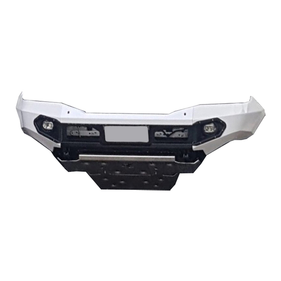
Next gen ranger bumper
Hide thumbs
Also See for Evo 3D:
- Installation instructions manual (18 pages) ,
- Installation instruction (16 pages) ,
- Install instruction (15 pages)

Related Manuals for RHINO Evo 3D


Summary of Contents for RHINO Evo 3D
- Page 1 Next Gen Ranger Bumper Evo 3D Fitting Instructions Ph: 1300 885 841 | Email: sales@rhino4x4.com.au | Website: www.rhino4x4.com.au www.rhino4x4.com.au...
- Page 2 Rhino 4x4 dealer. Welcome to the Rhino 4x4 team! Do not attach VFPS vehicle using any fixing points not intended for this purpose. Do not use this product on any other vehicle make or model, other than those specified.
- Page 3 Block 1: Preparing the Chassis Assemble all parts displayed in the table and image. Release all clips from the plastic cover. Remove the plastic cover, pulling it out from under the air intake. Release plastic clips from the inside of the flares.
- Page 4 Block 1: Preparing the Chassis Continue to remove all remaining bolts from the underside of the bumper. Remove the 2 x 10mm hex bolts and 3 plastic clips seen behind the back of the grille. Remove the wheel arch liner cover. Remove the 3 x 10mm hex bolts inside the cover.
- Page 5 Block 1: Preparing the Chassis Clamp the headlight washer hose and unplug the line. Remove the camera wire from the location tab slot. Disconnect the main harness plug. Pull back the front of the flare slightly. There are clips that will release when pulled.
- Page 6 Block 1: Preparing the Chassis Pull forwards and downwards on the bumper to now remove it. If stuck, the locational pins and clips can be accessed through the access hole in the wheel arch. Once the bumper is off, the grille can be removed. Remove the polystyrene bumper support from the lower cross member.
- Page 7 Block 1: Preparing the Chassis Reposition the horns to the position shown. It may be required to trim the plastic on the radiator surround for clearance. Trim the plastic in front of the radiator along the lines shown. Pin 7 For wiring the fog lights, unplug the 16 pin plug.
- Page 8 Attach the winch cradle to the recovery point brackets using the factory bolts, take care to align the intercooler mounts with the support brackets. Attach the Rhino 4x4 recovery points to the underside chassis, leaving some movement at this stage.
- Page 9 Block 2: Installing the Front Bar The sensors will be re-mounted to the bar using the provided sensor clips. The sensor housing may require trimming to allow installation in the direction shown. The outermost sensor clips will have to be mounted to the flare extensions prior to the extensions being installed.
- Page 10 Block 2: Installing the Front Bar Install the infills on top of the wings prior to installing the wings. There is no need to over tighten these are it may require later adjustment. Install the rubber strip along the top of the wing, this also must be completed prior to installing the wing.
- Page 11 Block 2: Installing the Front Bar Install the wing support brackets loosely. Check the bash plate aligns with the holes on the bash plate bracket before tightening. Tighten the wings and upper mid section. Tighten the top and bottom of the wing supports, it may be required to push/pull the wing slightly while tightening the top wing support bolts to achieve the best alignment.
- Page 12 Block 2: Installing the Front Bar Install the under wing cover plates. The wheel arch liner may then require trimming if larger tires are being installed. If a winch is being installed, it can now be lowered to the cradle from behind the upper mid section.
- Page 13 Installation complete! Thank-you for becoming a part of the Rhino 4x4 team, your support allows us to continue providing the 4x4 industry with quality products. We are always looking for ways to make your experience with us even better, so please take the chance to share your thoughts on our product by accessing the survey below.
- Page 14 Appendix 1.0 - Light Wiring Harness High Beam Trigger Vehicle Earth Switch in the Cabin Positive Battery Terminal If using the high beam trigger please snip this loop. Light Connection Alternatively the light will turn on and off only with the switch.
Need help?
Do you have a question about the Evo 3D and is the answer not in the manual?
Questions and answers