Tektronix TDS 510A Service Manual
Digitizing oscilloscope
Hide thumbs
Also See for TDS 510A:
- Instruction manual (116 pages) ,
- Programmer's manual (433 pages) ,
- User manual (232 pages)
Table of Contents
Advertisement
Quick Links
A l l t e s t I n s t r u me n t s , I n c .
5 0 0 C e n t r a l A v e .
F a r mi n g d a l e , N J 0 7 7 2 7
P : ( 7 3 2 ) 9 1 9 - 3 3 3 9
F : ( 7 3 2 ) 9 1 9 - 3 3 3 2
a l l t e s t . n e t
s s a l e s @ a l l t e s t . n e t
T h e t e s t & me a s u r e me n t
e q u i p me n t y o u n e e d a t
t h e p r i c e y o u w a n t .
A l l t e s t c a r r i e s t h e w o r l d ' s l a r g e s t s e l e c t i o n o f
u s e d / r e f u r b i s h e d b e n c h t o p t e s t & me a s u r e me n t
e q u i p me n t a t 5 0 % t h e p r i c e o f n e w .
O O u r e q u i p me n t i s g u a r a n t e e d w o r k i n g , w a r r a n t i e d , a n d
a v a i l a b l e w i t h c e r t i f i e d c a l i b r a t i o n f r o m o u r i n - h o u s e s t a f f
o f t e c h n i c i a n s a n d e n g i n e e r s .
• 1 0 + f u l l t i me t e c h n i c i a n s w i t h o v e r 1 5 0 y e a r s o f
s p e c i a l i z a t i o n
• 9 0 d a y w a r r a n t y & 5 d a y r i g h t o f r e t u r n o n a l l
e q u i p me n t
• • 1 - 3 y e a r w a r r a n t i e s f o r n e w a n d
p r e mi u m- r e f u r b i s h e d e q u i p me n t
• E v e r y u n i t t e s t e d t o O E M s p e c i f i c a t i o n s
• S a t i s f a c t i o n g u a r a n t e e d
Y o u h a v e p l a n s , w e w i l l h e l p y o u a c h i e v e t h e m.
A n y p r o j e c t . A n y b u d g e t .
t
G e t a q u o t e t o d a y !
C C a l l ( 7 3 2 ) 9 1 9 - 3 3 3 9 o r e ma i l s a l e s @a l l t e s t . n e t .
Advertisement
Table of Contents

Related Manuals for Tektronix TDS 510A


Summary of Contents for Tektronix TDS 510A
- Page 1 T h e t e s t & me a s u r e me n t e q u i p me n t y o u n e e d a t t h e p r i c e y o u w a n t . A l l t e s t I n s t r u me n t s , I n c .
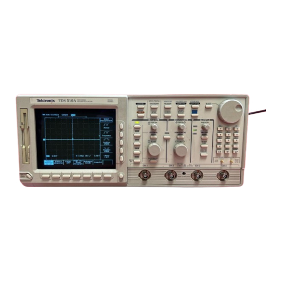
- Page 2 Service Manual TDS 510A Digitizing Oscilloscope 070-9704-02 Warning The servicing instructions are for use by qualified personnel only. To avoid personal injury, do not perform any servicing unless you are qualified to do so. Refer to all safety summaries prior to...
- Page 3 Copyright © Tektronix, Inc. All rights reserved. Tektronix products are covered by U.S. and foreign patents, issued and pending. Information in this publication supercedes that in all previously published material. Specifications and price change privileges reserved. Printed in the U.S.A.
- Page 4 Tektronix, with shipping charges prepaid. Tektronix shall pay for the return of the product to Customer if the shipment is to a location within the country in which the Tektronix service center is located.
- Page 6 H Eliminates unexpected service expenses For Information and Ordering For more information or to order Service Assurance, contact your Tektronix representative and provide the information below. Service Assurance may not be available in locations outside the United States of America.
- Page 8 ..........3–1 TDS 510A Service Manual...
- Page 9 4–16 TDS 510A Test Record ..........
- Page 10 ........10–2 TDS 510A Service Manual...
-
Page 11: Table Of Contents
..... . 4–70 Figure 4–29: Triggered Signal Range Test – 300 mV ....4–72 TDS 510A Service Manual... -
Page 12: Figure 4-10: Initial Test Hookup
......... . 6–31 TDS 510A Service Manual... - Page 13 ........10–12 TDS 510A Service Manual...
- Page 14 ....5–5 Table 5–5: GPIB Board Configuration1 ......5–7 TDS 510A Service Manual...
- Page 15 ..........7–7 viii TDS 510A Service Manual...
- Page 16 Provide Proper Ventilation. To prevent product overheating, provide proper ventilation. Do Not Operate With Suspected Failures. If you suspect there is damage to this product, have it inspected by qualified service personnel. TDS 510A Service Manual...
- Page 17 WARNING indicates an injury hazard not immediately accessible as you read the marking. CAUTION indicates a hazard to property including the product. Symbols on the Product. The following symbols may appear on the product: DANGER Protective Ground ATTENTION Double High Voltage (Earth) Terminal Refer to Manual Insulated TDS 510A Service Manual...
- Page 18 To avoid electric shock, do not touch exposed connections. X-Radiation. To avoid x-radiation exposure, do not modify or otherwise alter the high-voltage circuitry or the CRT enclosure. X-ray emissions generated within this product have been sufficiently shielded. TDS 510A Service Manual...
- Page 19 Service Safety Summary TDS 510A Service Manual...
- Page 20 Preface This preface contains information needed to properly use this manual to service the TDS 510A Digitizing Oscilloscope, as well as general information critical to safe and effective servicing of this oscilloscope. Manual Structure This manual is divided into sections, such as Specification and Theory of Operation.
- Page 21 Related Manuals The TDS 510A Digitizing Oscilloscope comes with the following manuals: TDS 420A, TDS 430A, TDS 460A & TDS 510A User Manual contains a tutorial to quickly show you how to operate the TDS 510A Digitizing Oscilloscope and an in depth discussion of how to more completely use their features. Applica- tions are also discussed.
- Page 22 Preface TDS Family Programmer Manual contains information for programmed operation via the GPIB interface. Included are the complete command set, setup information, and programming examples. TDS 510A Technical Reference contains performance verification procedures and specifications. TDS 510A Service Manual...
- Page 23 Preface TDS 510A Service Manual...
- Page 24 Installation Procedures, also found in Section 6. Service Offerings Tektronix provides service to cover repair under warranty as well as other services that may provide a cost-effective answer to your service needs. Whether providing warranty repair service or any of the other services listed below, Tektronix service technicians, trained on Tektronix products, are best equipped to service your TDS 510A Digitizing Oscilloscope.
- Page 25 Of these services, the annual maintenance agreement offers a particularly cost-effective approach to service for many owners of the TDS 510A Digitizing Oscilloscope. Such agreements can be purchased to span several years. On-Site Service. The annual maintenance agreement can be purchased with on-site service, with repair and calibration done at your facility.
- Page 26 Introduction Before You Begin This manual is for servicing the TDS 510A Digitizing Oscilloscope. To prevent injury to yourself or damage to the oscilloscope, do the following tasks before you attempt service: H Be sure you are a qualified service person.
- Page 27 Introduction TDS 510A Service Manual...
- Page 29 Specifications This chapter begins with a general description of the traits of the TDS 510A Digitizing Oscilloscope. Three sections follow, one for each of three classes of traits: nominal traits, warranted characteristics, and typical characteristics. General Product Description The TDS 510A is a portable, four-channel oscilloscope suitable for use in a variety of test and measurement applications and systems.
- Page 30 Full, 100 MHz, and 20 MHz bandwidth. Such icons allow you to more readily determine status or the available settings. 1–2 TDS 510A Service Manual...
- Page 31 (auto or normal), and holdoff. H Logic (main-trigger system): This type of triggering can be based on pattern (asynchronous) or state (synchronous). In either case, logic triggering is 1–3 TDS 510A Service Manual...
- Page 32 Help and autoset can assist you in setting up the oscilloscope to take your measurements. Help Help displays operational information about any front-panel control. When help mode is in effect, manipulating any front-panel control causes the oscilloscope to 1–4 TDS 510A Service Manual...
- Page 33 3.5 inch, DOS 3.3-or-later compatible disk. The disk is available as option 1F. Any or all of the saved waveforms may be displayed for comparison with the waveforms currently being acquired. 1–5 TDS 510A Service Manual...
- Page 34 The oscilloscope also provides an easy way to focus in on those waveform features you wish to examine up close. By invoking zoom, you can magnify the waveform parameter using the vertical and horizontal controls to expand (or contract) and position it for viewing. 1–6 TDS 510A Service Manual...
- Page 35 Nominal Traits This section contains tables that list the electrical and mechanical nominal traits that describe the TDS 510A Digitizing Oscilloscope. Nominal traits are described using simple statements of fact, such as “Four, all identical” for the trait “Input Channels, Number of,” rather than in terms of limits that are performance requirements.
- Page 36 1/(Waveform Interval) for the waveform record, where the waveform interval (WI) is the time between the samples in the waveform record. The maximum record length of 50,000 samples is selectable with all acquisition modes except Hi Res. In Hi Res, the maximum record length is 15,000 samples. 1–8 TDS 510A Service Manual...
- Page 37 3.78 inches vertically Waveform Display Graticule Single Graticule: 401 501 pixels, 8 10 divisions, where divisions are 1 cm by 1 cm Waveform Display Grey Scale Sixteen levels in infinite-persistence and variable persistence display styles. 1–9 TDS 510A Service Manual...
- Page 38 Forced-air circulation with no air filter Construction Material Chassis parts constructed of aluminum alloy; front panel constructed of plastic laminate; circuit boards constructed of glass-laminate. Cabinet is aluminum and is clad in Tektronix Blue vinyl material. Finish Type Tektronix Blue vinyl-clad aluminum cabinet...
- Page 39 Height: 193 mm (7.6 in), with the feet installed. Width: 445 mm (17.5 in), with handle. Depth: 434 mm (17.1 in), with front cover installed. Rackmount oscilloscope Height: 178 mm (7.0 in). Width: 483 mm (19.0 in). Depth: 558.8 mm (22.0 in). 1–11 TDS 510A Service Manual...
- Page 40 Nominal Traits 1–12 TDS 510A Service Manual...
- Page 41 Warranted Characteristics This section lists the electrical and environmental warranted characteristics that describe the TDS 510A Digitizing Oscilloscope. Warranted characteristics are described in terms of quantifiable performance limits which are warranted. NOTE. In these tables, those warranted characteristics that are checked in the procedure Performance Verification, found in Section 4, appear in boldface type under the column Name.
-
Page 42: Delay Time
The AC Coupled Lower Frequency Limits are reduced by a factor of 10 when 10X, passive probes are used. Table 1–8: Warranted Characteristics — Time Base System Name Description 25 ppm over any w1 ms interval Accuracy, Long Term Sample Rate and Delay Time 1–14 TDS 510A Service Manual... - Page 43 The waveform interval (WI) is the time between the samples in the waveform record. Also, see the footnote for the characteristics Sample Rate Range and Equivalent Time or Interpolated Waveform Rate on page 1–8 and net offset on page 1–14. 1–15 TDS 510A Service Manual...
- Page 44 User-Misuse Simulation Electrostatic Discharge Susceptibility: Up to 8 kV with no change to control settings or impairment of normal operation; up to 15 kV with no damage that prevents recovery of normal operation by the user 1–16 TDS 510A Service Manual...
-
Page 45: Table 1-17: Certifications And Compliances
CAT II Local-level mains, appliances, portable equipment CAT I Signal levels in special equipment or parts of equipment, telecommu- nications, electronics Pollution Degree 2 Do not operate in environments where conductive pollutants may be present. 1–17 TDS 510A Service Manual... - Page 46 Specifications 1–18 TDS 510A Service Manual...
-
Page 47: Table 1-13: Typical Characteristics - Signal Acquisition System
Typical Characteristics The tables in this section list the typical characteristics that describe the TDS 510A Digitizing Oscilloscope. Typical characteristics are described in terms of typical or average performance. Typical characteristics are not warranted. Table 1–13: Typical Characteristics — Signal Acquisition System... -
Page 48: Table 1-14: Typical Characteristics - Time Base System
The limits are given for signals having pulse height 5 div, pulse duration v 10 divisions, reference level = 50% mid-point, filter set to Sin (x) /x acquired at 5 mV/div, 1.4 v v 5, where S is the sample interval and t is the signal rise time. 1–20 TDS 510A Service Manual... -
Page 49: Table 1-15: Typical Characteristics - Triggering System
For <5 ms pulse width or rearm time, 2 divisions are required. Glitch Sync Width (Option 05 Video Trigger) min. 400 ns for HDTV signals Sync Duty Cycle min. 50 to 1 (Option 05 Video Trigger) 1–21 TDS 510A Service Manual... -
Page 50: Table 1-16: Typical Characteristics - Data Handling
Data is maintained by small lithium-thionyl-chloride batteries internal to the memory ICs. The amount of lithium is so small in these ICs that they can typically be safely disposed of with ordinary garbage in a sanitary landfill. 1–22 TDS 510A Service Manual... - Page 52 Do not defeat the grounding connection. Any interruption of the grounding connection can create an electric shock hazard. For electric shock protection, the grounding connection must be made before making connection to the oscilloscope input or output terminals. 2–1 TDS 510A Service Manual...
-
Page 53: Table 2-1: Power-Cord Conductor Identification
The on-board batteries of the memory modules have a shelf life of about five years. Partial or total loss of stored settings upon power on may indicate that the memory modules need to be replaced. 2–2 TDS 510A Service Manual... - Page 54 Installation Table 2–2: Power Cord Identification Plug Configuration Normal Usage Option Number North America Standard 115 V Europe 230 V United Kingdom 230 V Australia 230 V North America 230 V Switzerland 230 V 2–3 TDS 510A Service Manual...
- Page 55 (The feet on the bottom of the oscilloscope provide the required clearance when set on flat surfaces.) The top of the oscilloscope does not require ventilation clearance. CAUTION. If air flow is restricted, the oscilloscope power supply may temporarily shut down. 2–4 TDS 510A Service Manual...
- Page 56 A signal path compensation is required. Voltage Reference A voltage reference adjustment is required (Chapter 5). Frequency Response A frequency response adjustment is required (Chapter 5). Error Log Errors logged are lost. Reference Waveforms Waveform Lost Saved Setups Setup Lost 2–5 TDS 510A Service Manual...
- Page 57 126 g (275 pounds) and with an inside dimension at least 15 cm (six inches) greater than the oscilloscope dimensions. If the oscilloscope is being shipped to a Tektronix Service Center, enclose the following information: the owners address, name and phone number of a contact person, type and serial number of the oscilloscope, reason for returning, and a complete description of the service required.
- Page 58 Operating Instructions This section contains general operating instructions for the TDS 510A Digitizing Oscilloscope. The complete user instructions are found in the User Manual. Additional instructions are integrated into the service procedures found in later sections of this manual. For instance, the procedures found in Chapter 4 Performance Verification contain instructions for making the front-panel settings required to check each instrument characteristic included there.
- Page 59 Push the SHIFT, then the STATUS front-panel buttons to display the status Menu menu. You will find messages reflecting the state of the acquisition system, whether it is running or stopped (and if it is stopped, why), as well as setup-re- lated information. 2–8 TDS 510A Service Manual...
- Page 60 Access all horizontal functions Access all trigger functions from this front-panel control block. from this front-panel block. this front-panel block. Special Function Controls: Access all functions except vertical, horizontal, and trigger functions from this front-panel control block. 2–9 TDS 510A Service Manual...
- Page 61 Vertically (1) and horizontally (2) scale and position the waveform(s) selected. Example: Set the scale to 100 mV/div and center the waveform on screen. d. Stop and start acquiring waveforms (3). Example: Push RUN/STOP if not acquiring. 2–10 TDS 510A Service Manual...
- Page 62 0 V. d. Select a function from the main menu using the main menu buttons (12). A side menu for selecting among that the available settings for that function appears. Example: Push Coupling (13). 2–11 TDS 510A Service Manual...
- Page 63 Toggle back to Edge. c. Complete the setting of the desired mode by selecting from the main menu and the side menu that results. Example: Push Mode & Holdoff (16), and then push Normal (15). 2–12 TDS 510A Service Manual...
- Page 64 The general purpose knob can also be assigned to control the following functions: H Cursor positioning H Display intensities H Delay time 2–13 TDS 510A Service Manual...
- Page 65 In the Display menu, you can set the following functions: H Intensity: waveforms, readouts, graticule. H Style of waveform display(s): vectors or dots, intensified or non-intensified samples, and infinite or variable persistence. 2–14 TDS 510A Service Manual...
- Page 66 From the Utility menu, you can configure the GPIB port (talk/listen, address, etc.) and access internal routines for self diagnostics and self compensation. Instructions for setting up communication over the GPIB are found in Chapter 5, Adjustment Procedures. 2–15 TDS 510A Service Manual...
- Page 67 Operating Instructions 2–16 TDS 510A Service Manual...
- Page 69 Circuit Description This chapter describes the electrical operation of the TDS 510A Digitizing Oscilloscope using the major circuit blocks or modules. This chapter has two main parts: H Logic Conventions describes how logic functions are discussed and represented in this manual.
- Page 70 All information (waveforms, text, graticules, and pictographs) is displayed by the A20 Display system. The Display system generates the high voltages necessary to drive the display tube. It also contains the video amplifier, horizontal oscillator, and the vertical and horizontal yoke driver circuitry. 3–2 TDS 510A Service Manual...
- Page 71 If the power is going off, the power supply sends a power fail (~PF) warning to the processor system. The fan provides forced air cooling for the oscilloscope. It connects to +25 V from the Low Voltage Power Supply by way of the A11 DRAM Processor/Dis- play module. 3–3 TDS 510A Service Manual...
- Page 72 Circuit Description 3–4 TDS 510A Service Manual...
- Page 74 (See Equipment Required beginning on page 4–16.) If you are not familiar with operating this oscilloscope, read the user manual. These contain instructions that will acquaint you with the use of the front-panel controls and the menu system. 4–1 TDS 510A Service Manual...
- Page 75 STOP. The symbol at the left is accompanied by information you must read to do the procedure properly. H Refer to Figure 4–1: “Main menu” refers to the menu that labels the seven menu buttons under the display; “side menu” refers to the menu that labels 4–2 TDS 510A Service Manual...
- Page 76 CLEAR MENU is pressed. Vertical scale, horizontal scale, and trigger level readouts Pop-up menu Main menu display area. Readouts in lower graticule area move here when CLEAR MENU is pressed. Figure 4–1: Map of Display Functions 4–3 TDS 510A Service Manual...
- Page 77 Performance Verification Procedures 4–4 TDS 510A Service Manual...
- Page 78 When the verification is finished, the resulting status will appear on the screen. d. Confirm no failures are found: Verify that no failures are found and reported on-screen. e. Confirm the three adjustment sections have passed status: 4–5 TDS 510A Service Manual...
-
Page 79: Figure 4-2: Verifying Adjustments And Signal-Path Compensation
Pass appears under Signal Path in the main menu. See Figure 4–2. Highlight Cal Verify Pass Verify Pass Figure 4–2: Verifying Adjustments and Signal-Path Compensation 2. Return to regular service: Press CLEAR MENU to exit the system menus. 4–6 TDS 510A Service Manual... - Page 80 (typically black) to PROBE COMPENSA- TION GND. If using a P6243 or P6245 probe, you may want to attach a Y-lead connector and two SMD KlipChips as shown in Figure 4–3. 4–7 TDS 510A Service Manual...
-
Page 81: Figure 4-3: Universal Test Hookup For Functional Tests
H Press the front-panel button that corresponds to the channel you are to verify. H Move the probe to the channel you selected. b. Match the trigger source to the channel selected: H Press TRIGGER MENU. 4–8 TDS 510A Service Manual... - Page 82 H Envelope mode displays an actively acquiring waveform on-screen with the noise displayed. H Average mode displays an actively acquiring waveform on-screen with the noise reduced. Test all channels: Repeat substeps a through e until all four input channels are verified. 4–9 TDS 510A Service Manual...
- Page 83 200 ms returns the period to about five divisions. c. The horizontal POSITION knob positions the signal left and right on screen when rotated. 3. Remove the test hookup: Disconnect the probe from the channel input and the probe-compensation terminals. 4–10 TDS 510A Service Manual...
- Page 84 (Leave the signal untriggered, which is indicated by the display not updating.) H Pressing SET LEVEL TO 50% triggers the signal that you just left untriggered. (Leave the signal triggered.) 4–11 TDS 510A Service Manual...
- Page 85 H Verify that the trigger READY indicator on the front panel flashes about once every second as the waveform is updated on-screen. 4. Remove the test hookup: Disconnect the probe from the channel input and the probe-compensation terminals. 4–12 TDS 510A Service Manual...
- Page 86 To File. H Turn the general purpose knob to select the file to save. Choose TEK?????.SET (or fdo:). With this choice, you will save a file starting with TEK, then containing 5-numbers, and a .SET extension. 4–13 TDS 510A Service Manual...
- Page 87 3. Remove the test hookup: H Disconnect the probe from the channel input and the probe-compensa- tion terminals. H Remove the disk from the disk drive. Do this by pushing in the tab of the disk drive. 4–14 TDS 510A Service Manual...
- Page 88 Performance Tests This section contains a collection of procedures for checking that the TDS 510A Digitizing Oscilloscope performs as warranted. The procedures are arranged in four logical groupings: Signal Acquisition System Checks, Time Base System Checks, Triggering System Checks, and Output Ports Checks.
-
Page 89: Table 4-1: Test Equipment
Used to Test Video Option 05 Equipped Instruments Only 15. Oscillator, Leveled Sine 60 Hz Sine wave Wavetek 9100 with options Used to Test Video Option 05 wave Generator 100 and 250 (or, optionally, Equipped Instruments Only Tektronix SG 502) 4–16 TDS 510A Service Manual... - Page 90 To make measurements beyond 8 V, use either the P6139A probe (good to 500 V), or refer to the catalog for a recom- mended probe. You can replace items 19, 20, or 21 with a Tektronix SG503 (item 25) or SG504 (item 26) – if available. 4–17...
- Page 91 Performance Tests 4–18 TDS 510A Service Manual...
- Page 92 Performance Tests TDS 510A Test Record Photocopy this and the next three pages and use them to record the performance test results for your TDS 510A Digitizing Oscilloscope. Test Record Instrument Serial Number: Certificate Number: Temperature: RH %: Date of Calibration:...
- Page 93 – 17.6075 V +5 Div position setting, –10 V offset Analog Bandwidth 100 mV 424 mV __________ __________ 100 mV 424 mV __________ __________ 100 mV 424 mV __________ __________ 100 mV 424 mV __________ __________ 4–20 TDS 510A Service Manual...
- Page 94 Low 0.25 V DELAYED TRIGGER OUTPUT, 50 W High High 1.0 V __________ __________ __________ __________ Low 0.25 V DELAYED TRIGGER OUTPUT, 1 MW High High 2.5 V __________ __________ __________ __________ Low 0.7 V 4–21 TDS 510A Service Manual...
- Page 95 CH 3 or AX 1 SIGNAL OUTPUT, 50 W Pk-Pk 45 mV __________ __________ Pk-Pk 55 mV Probe Compensator Output Signal Frequency (CH1 Freq.) 950 Hz __________ __________ 1.050 kHz Voltage (difference) 495 mV __________ __________ 505 mV 4–22 TDS 510A Service Manual...
- Page 96 Set the vertical scale: Set the vertical SCALE to one of the settings listed in Table 4–2 that is not yet checked. (Start with the first setting listed.) 4–23 TDS 510A Service Manual...
-
Page 97: Table 4-2: Dc Offset Accuracy (Zero Setting)
H CHECK that the measurement results are within the limits listed for the current vertical scale setting. H Enter voltage on test record. H Repeat substeps b through f until all vertical scale settings listed in Table 4–2, are checked for the channel under test. 4–24 TDS 510A Service Manual... -
Page 98: Figure 4-4: Measurement Of Dc Offset Accuracy At Zero Setting
Two dual-banana connectors (Item 6) Required One BNC T connector (Item 7) One DC calibration generator (Item 9) Two precision coaxial cables (Item 5) Prerequisites The oscilloscope must meet the prerequisites listed on page 4–15 4–25 TDS 510A Service Manual... -
Page 99: Figure 4-5: Initial Test Hookup
2. Confirm input channels are within limits for DC accuracy at maximum offset and position: Do the following substeps — test CH 1 first, skipping substep 2a since CH 1 is already selected from step 1. 4–26 TDS 510A Service Manual... -
Page 100: Table 4-3: Dc Voltage Measurement Accuracy
H Press VERTICAL MENU. Press the main-menu button Position. H Use the keypad to set vertical position to –5 divisions (press –5, then ENTER, on the keypad). The baseline level will move off screen. H Press the main-menu button Offset. 4–27 TDS 510A Service Manual... -
Page 101: Figure 4-6: Measurement Of Dc Accuracy At Maximum Offset And Position
H CHECK that the Mean measurement readout on screen is within the limits listed for the current vertical scale setting and position/offset/ generator settings. Enter the value on test record. 4–28 TDS 510A Service Manual... - Page 102 H Turn the horizontal SCALE knob to 50 ns. Press SHIFT; then press ACQUIRE MENU. H Press the main-menu button Mode; then press the side-menu button Average 16. H Press MEASURE. Press the main-menu button High–Low Setup; then press the side-menu button Min–Max. 4–29 TDS 510A Service Manual...
-
Page 103: Figure 4-7: Initial Test Hookup
H Press the side-menu W button to toggle it to the 50 W setting. d. Set the vertical scale: Set the vertical SCALE to one of the settings listed in Table 4–4 not yet checked. (Start with the 100 mV setting.) 4–30 TDS 510A Service Manual... -
Page 104: Table 4-4: Analog Bandwidth
Measure the test signal: H Set the frequency of the generator, as shown on screen, to the test frequency in Table 4–4 that corresponds to the vertical scale set in substep d. See Figure 4–8. 4–31 TDS 510A Service Manual... - Page 105 Table 4–4 (that is, skip the following substep, h) if this oscilloscope has passed the 100 mV vertical scale setting just checked in this procedure and the Verify Internal Adjustment, Self Compensation, and Diagnostics procedure found under Self Tests, on page 4–5. 4–32 TDS 510A Service Manual...
- Page 106 1. Install the test hookup and preset the instrument controls: a. Initialize the front panel: H Press save/recall SETUP. H Press the main-menu button Recall Factory Setup. H Press the side-menu button OK Confirm Factory Init. 4–33 TDS 510A Service Manual...
- Page 107 TO 50% frequently to speed up the updating of the waveform amplitude on screen. b. The horizontal SCALE should already be set to 500 ps. Push the front-panel ZOOM button, press the side-menu On button, set the 4–34 TDS 510A Service Manual...
- Page 108 General Purpose knob. (Press SELECT to switch between the two cursors.) See Figure 4–10 on page 4–36. 4–35 TDS 510A Service Manual...
- Page 109 Again use the cursors to measure the skew from CH1 to CH2, CH1 to CH3, and CH1 to CH4. Write down these numbers in the second measurement column of Table 4–5. Note that these numbers may be either positive or negative. 4–36 TDS 510A Service Manual...
-
Page 110: Table 4-5: Delay Between Channels Worksheet
Measurement Measurement by 2 Measurements CH1 to CH2 skew CH1 to CH3 skew CH1 to CH4 skew 3. Disconnect the hookup: Disconnect the cable from the generator output at the input connectors of the channels. 4–37 TDS 510A Service Manual... - Page 111 Modify the initialized front-panel control settings: H Set the vertical SCALE to 200 mV (or 500 mV with the optional Tektronix TG 501A Time Mark Generator) H Press VERTICAL MENU; then press the main-menu button Coupling. Press the side-menu button W to toggle it to the 50 W setting.
- Page 112 CHECK that the rising edge of the marker crosses the center horizontal graticule line at a point within 2.5 divisions of the center graticule. See Figure 4–12. H Enter number of divisions on the test record. 4–39 TDS 510A Service Manual...
- Page 113 Check Accuracy (Time) for Equipment One medium-frequency sine wave generator Required (Item 19 or, optionally, Item 25) Pulse-Glitch or Pulse-Width Triggering One 10X attenuator (Item 1) One 50 W, precision coaxial cable (Item 5) Prerequisites See page 4–15. 4–40 TDS 510A Service Manual...
- Page 114 Display the test signal: Set the output of the sine wave generator for a 100 MHz, five-division sine wave on screen. Press SET LEVEL TO 50%. b. Set the trigger mode: Press TRIGGER MENU. Now press the main-menu button Mode & Holdoff; then press the side-menu button Normal. 4–41 TDS 510A Service Manual...
- Page 115 Upper Limit readout until triggering is lost. H CHECK that the Upper Limit readout, after the oscilloscope loses triggering, is within 2.5 ns to 7.5 ns, inclusive. H Enter the time on test record. 4–42 TDS 510A Service Manual...
- Page 116 H Press SET LEVEL TO 50%. c. Check against limits: Do the following subparts in the order listed. H Press the side-menu button Lower Limit. H Use the general purpose knob to increase Lower Limit readout until triggering is lost. 4–43 TDS 510A Service Manual...
- Page 117 50 W Coaxial Cables Figure 4–15: Initial Test Hookup 1. Install the test hookup and preset the instrument controls: a. Hook up the test-signal source: H Set the output of the DC calibration generator to 0 volts. 4–44 TDS 510A Service Manual...
- Page 118 Level in the main menu, not the trigger readout in the graticule area. c. Read results (Check against limits): See Figure 4–16. H CHECK that the Level readout in the main menu is within 9.940 V to 10.060 V, inclusive. 4–45 TDS 510A Service Manual...
- Page 119 Select the Delayed time base: H Press HORIZONTAL MENU. H Press the main-menu button Time Base. H Press the side-menu buttons Delayed Only and Delayed Trigger- able. H Set D (delayed) horizontal SCALE to 500 ms. 4–46 TDS 510A Service Manual...
- Page 120 One 5X attenuator (Item 2) Prerequisites See page 4–15. 1. Install the test hookup and preset the instrument controls: a. Initialize the oscilloscope: H Press save/recall SETUP. H Press the main-menu button Recall Factory Setup. 4–47 TDS 510A Service Manual...
- Page 121 Connect the other output of the T connector to the AUX TRIG INPUT at the rear panel. See Figure 4–17. To AUX TRIG INPUT Sine Wave on Rear Panel Digitizing Oscilloscope Generator Figure 4–17: Initial Test Hookup 4–48 TDS 510A Service Manual...
- Page 122 Use the side menu to switch between trigger slopes. H Enter the pass/fail result for the main trigger on the test record. H Leave the Main trigger system triggered on the positive slope of the waveform before continuing to the next step. 4–49 TDS 510A Service Manual...
- Page 123 H Use the definition for stable trigger from step 2. H Press TRIGGER MENU; then press the main-menu button Source. H Press the side-menu button –more– until the side-menu label DC Aux appears; then press DC Aux. 4–50 TDS 510A Service Manual...
- Page 124 1. Connect the signal output of a high-frequency sine wave generator (Item 19 or, optionally, Item 26) to CH 1. b. Set the Main and Delayed Horizontal Scales: H Set the horizontal SCALE to 500 ps for the M (Main) time base. 4–51 TDS 510A Service Manual...
- Page 125 Two 50 W precision cables (Item 5) Equipment Main and Delayed Trigger Required One calibration generator (Item 10) Prerequisites See page 4–15. Also, the oscilloscope must have passed Check DC Voltage Measurement Accuracy on page 4–25. 4–52 TDS 510A Service Manual...
- Page 126 H Select 64 averages. Do this with the keypad or the general purpose knob. 2. Confirm Main and Delayed Trigger outputs are within limits for logic levels: a. Display the test signal: H Press WAVEFORM OFF to turn off CH 1. 4–53 TDS 510A Service Manual...
- Page 127 Coupling. Now press the side-menu button W to toggle it to the 50 W setting. H CHECK that the Ch2 High readout is 1.0 volt and that the Ch2 Low readout 0.25 volts. H Enter the high and low voltages on the test record. 4–54 TDS 510A Service Manual...
- Page 128 3. Confirm CH 3 output is within limits for gain: a. Measure gain: H Move the precision 50 W cable from the rear-panel DELAYED TRIGGER OUTPUT BNC to the rear-panel SIGNAL OUT BNC. H Push TRIGGER MENU. 4–55 TDS 510A Service Manual...
- Page 129 Two 50 W precision cables (Item 5) One DC calibration generator (Item 9) Prerequisites See page 4–15. Also, the oscilloscope must have passed Check Accuracy For Long-Term Sample Rate and Delay Time Measurements on page 4–38. 4–56 TDS 510A Service Manual...
- Page 130 H Press SET LEVEL TO 50%. H Use the vertical POSITION knob to center the display on screen. H Press SHIFT; then press ACQUIRE MENU. H Press the main-menu button Mode; then press the side-menu button Average. 4–57 TDS 510A Service Manual...
- Page 131 See Figure 4–22. H Enter the frequency on the test record. H Press MEASURE; then press the main-menu button Remove Measrmnt for Ch1. Press the side–menu Measurement 1. Figure 4–22: Measurement of Probe Compensator Frequency 4–58 TDS 510A Service Manual...
- Page 132 Figure 4–23: Subsequent Test Hookup e. Measure amplitude of the probe compensation signal: H Press SHIFT; then press ACQUIRE MENU. Press the side-menu button AVERAGE then enter 16 using the keypad or the general purpose knob. 4–59 TDS 510A Service Manual...
- Page 133 (top level). H CHECK that the difference obtained is within 495 mV to 505 mV, inclusive. H Enter the voltage difference on the test record. 3. Disconnect the hookup: Disconnect the cable from CH 1. 4–60 TDS 510A Service Manual...
- Page 134 Press the main-menu Bandwidth. h. Select 100 MHz from the side menu. Press the main-menu Fine Scale. Use the keypad to set the fine scale to 282mV (press 282, SHIFT, m, then ENTER). k. Press HORIZONTAL MENU. 4–61 TDS 510A Service Manual...
- Page 135 Digitizing Oscilloscope COMPST 75 W Terminator 75 W Cable Figure 4–25: Jitter Test Hookup b. CHECK that the oscilloscope lights up its front panel TRIG’D LED and it displays the waveform on screen. See Figure 4–26. 4–62 TDS 510A Service Manual...
- Page 136 Press CH1. m. Press SHIFT; then press ACQUIRE MENU. n. Press the main-menu Limit Test Setup. o. Toggle the side-menu Limit Test to ON. p. Toggle the side-menu Ring Bell if Condition Met to ON. 4–63 TDS 510A Service Manual...
- Page 137 Press the main-menu Limit Test Setup. x. Toggle the side-menu Ring Bell if Condition Met to OFF. y. Toggle the side-menu Limit Test to OFF. 4. Check Triggered Signal Range: Set up oscilloscope for Triggered Signal Test: a. Press MORE. 4–64 TDS 510A Service Manual...
- Page 138 CONFIRM that the TRIG’D LED stays lighted and that the waveform on screen is stable. That is, it does not move horizontally or vertically. Also, CONFIRM that the waveform on the screen has one positive pulse and a number of negative pulses. See Figure 4–28. 4–65 TDS 510A Service Manual...
- Page 139 CONFIRM that the TRIG’D LED stays lighted and that the waveform on screen is stable. That is, it does not move horizontally or vertically. Also, CONFIRM that the waveform on the screen has one positive pulse and a number of negative pulses. See Figure 4–29. 4–66 TDS 510A Service Manual...
- Page 140 H Use the keypad to set the horizontal scale (/div) to 5 ms (press 5, SHIFT, m, and then ENTER). b. Set up 60 Hz signal generator: H Connect the output of the signal generator to the CH2 input through a 50 W cable. See Figure 4–30. 4–67 TDS 510A Service Manual...
- Page 141 H Use the keypad to set the horizontal scale (/div) to 50 ms (press 50, SHIFT, m, and then ENTER). H Reconnect the output of the signal generator. Connect the composite signal connector of the PAL signal source (labeled COMPST on the 4–68 TDS 510A Service Manual...
- Page 142 Also, confirm that the waveform on the screen has one positive pulse and a number of negative pulses. See Figure 4–33. H Disconnect all test equipment from the oscilloscope. 4–69 TDS 510A Service Manual...
- Page 143 H Connect a composite output signal from the rear of the PAL signal source (labeled COMPST on the TSG 121) to the CH1 input through a 75 W cable and a 75 W terminator. See Figure 4–34. 4–70 TDS 510A Service Manual...
- Page 144 H Press the side-menu to Set to 50%. H Use the HORIZONTAL POSITION knob to move the falling edge of the sync pulse to two divisions to the left of center screen. See Figure 4–35. 4–71 TDS 510A Service Manual...
- Page 145 6.780us. H Use the HORIZONTAL POSITION knob to position the right cursor to center screen. H Verify that the cursor is positioned on a positive slope of the burst signal. See Figure 4–36. 4–72 TDS 510A Service Manual...
- Page 146 H Use the keypad to set the field rate to 60.05 Hz (press 60.05, then ENTER). H Press the side-menu Lines. H Use the keypad to set the field rate to 793 lines (press 793, then ENTER). H Press the side-menu Fields. 4–73 TDS 510A Service Manual...
- Page 147 H Set PULSE DURATION to 50 ns. H Set PERIOD to 10 ms. H Set OUTPUT (VOLTS) to –1 for LOW LEVEL and +1 for HIGH LEVEL. H Depress the COMPLEMENT button. H Be sure BACK TERM is depressed (in). 4–74 TDS 510A Service Manual...
- Page 148 H Turn the pulse generator OUTPUT (VOLTS) control until the signal on the oscilloscope shows a one division negative going pulse. See Figure 4–38. NOTE. You may need to adjust the trigger level control to obtain a stable trigger. 4–75 TDS 510A Service Manual...
- Page 149 NOTE. The pulse duration and period adjustments are critical in making this measurement. If the pulse duration and/or the duty cycle are not stable, the FLEXFMT function may not function. You must take care when making these adjustments. 4–76 TDS 510A Service Manual...
- Page 150 H CONFIRM that the TRIG’D LED is lighted and the waveform is stable. H Press Sync Polarity. H Press Pos Sync. H Push the pulse generator COMPLEMENT button out. H CONFIRM that the TRIG’D LED is lighted and the waveform is stable. 4–77 TDS 510A Service Manual...
- Page 151 Sine wave generator (Item 19) Required Level meter and power sensor (Item 20) Power splitter (Item 21) Two male N to female BNC adapters (Item 23) One precision coaxial cable (Item 5) Prerequisites See page 4–15. 4–78 TDS 510A Service Manual...
- Page 152 H Input the correction factor for the new frequency into the level meter. H Adjust the sine wave generator amplitude until the level meter again reads the value noted in step 3. The signal amplitude is now correctly set for the new frequency. 4–79 TDS 510A Service Manual...
- Page 153 3. Record the reference level: H Disconnect the sine wave generator from the oscilloscope. H Connect the sine wave generator to the power sensor. H Note the level meter reading. 4–80 TDS 510A Service Manual...
- Page 154 3. The signal amplitude is now correctly set for the new frequency. H Disconnect the sine wave generator from the power sensor. H Connect the sine wave generator to the oscilloscope. 4–81 TDS 510A Service Manual...
- Page 155 Performance Tests 4–82 TDS 510A Service Manual...
- Page 157 Adjustment Procedures This chapter contains information needed to adjust the TDS 510A Digitizing Oscilloscope. Description The Adjustment Procedures are divided into six sections: H General information about adjusting the oscilloscope. H A list of equipment required to perform the adjustments.
- Page 158 H A high-density floppy drive: 3.5 inch (1.44 M) or 5.25 inch (1.2 M). H A GPIB board — National InstrumentsR GPIB-PCII, GPIB-PCIIA or GPIB-PCII/IIA. (A PC-GPIB Package that includes the PCII/IIA is available — Tektronix part number S3FG210) H Suitable keyboard and monitor. Optional Peripherals Installation of a math coprocessor in your system is strongly recommended to decrease the time required to adjust the oscilloscope.
-
Page 159: Table 5-1: Calibration Tests
However, usually all adjustments are made unless you are adjusting circuits in the course of troubleshooting the oscilloscope. Read the information under Complete Adjustment, Adjustment After Repair, and Adjustment Dependencies before doing an individual adjustment. 5–3 TDS 510A Service Manual... -
Page 160: Table 5-2: Adjustments Required For Module Replaced
Voltage Reference Adjustment None Frequency Response Adjustment Voltage Reference (SPC and all tests) Pulse Trigger Adjustment Voltage Reference (SPC and all tests) P6139A Probe Adjustment Voltage Reference and Frequency Response (SPC and all tests) Display Adjustment None 5–4 TDS 510A Service Manual... -
Page 161: Table 5-4: Test Equipment, Fixtures, And Supplies
Adjustment Procedures Equipment Required Table 5–4 lists the test equipment required to adjust the TDS 510A Digitizing Oscilloscope. Table 5–4: Test Equipment, Fixtures, and Supplies Item Number and Description Minimum Requirements Example Purpose Adapter, BNC-Female-to- Tektronix part number Tektronix part number... - Page 162 Leveled Sine Software-based Adjustments Wave, High-Frequency amplitude from 0.5 V to 4 V Wave Generator with its level- into 50 W; 6 MHz reference; ing head or a Tektronix harmonic content: 2 harmonic SG 5030 Programmable down –25 dB from fundamental;...
- Page 163 “Purpose” in Table 5–4 starting on page 5–5. Adjustments 1. Hook up the oscilloscope: a. Connect the GPIB cable (Item 6) to the GPIB port at the computer rear panel. (When multiple GPIB cards are installed, connect to the GPIB0 card.) 5–7 TDS 510A Service Manual...
- Page 164 Insert the adjustment tool (Item 3) in the hole nearest the front of the oscilloscope about 1/2 inch to engage the rocker switch. c. Push to rock the switch to its unprotected (enabled) position. See Figure 5–1. 5–8 TDS 510A Service Manual...
- Page 165 Push to rock the switch to its protected (disabled) position. d. To do a complete adjustment as defined on page 5–3, you must also do the procedure Compensate the Probe on page 5–10 if you are using the P6139A probe. 5–9 TDS 510A Service Manual...
- Page 166 H Press SHIFT; then press ACQUIRE MENU. H Press the main-menu button Mode. Then press the side-menu button Average 16. 2. Compensate the Probe: a. Locate the probe compensation hole in the side of the probe body. 5–10 TDS 510A Service Manual...
- Page 167 Using the probe compensation tool, adjust the probe for best square wave compensation (flat as possible across its top) (See figures 5–3 and 5–4). Figure 5–3: Performing Probe Compensation Probe compensated correctly Probe overcompensated Probe undercompensated Figure 5–4: Proper and Improper Probe Compensation 5–11 TDS 510A Service Manual...
- Page 168 See Figure 5–6. H Connect the female-to-female adapter to a BNC-to-probe tip adapter. H Plug the probe tip from the probe on CH 1 into the BNC-to-probe tip adapter. 5–12 TDS 510A Service Manual...
- Page 169 Min-Max. H Press the main-menu button Select Measrmnt for Ch1. H Repeatedly press the side-menu button –more– until Pk-Pk appears in the side menu. Press the side-menu button Pk-Pk. H Press CLEAR MENU. 5–13 TDS 510A Service Manual...
- Page 170 One 50 W precision cable (Item 8) One tunnel diode pulser (Item 17) One BNC female-to-female adapter (Item 1) One BNC to probe adapter (Item 2) One 10X attenuator (Item 4) One P6139A 10X probe (Item 16) 5–14 TDS 510A Service Manual...
- Page 171 50 W precision cable, to the input of a tunnel diode pulser. See Figure 5–8. H Connect the output of the tunnel diode pulser through a 10X attenuator to CH 1. H Set the triggering level of the tunnel diode pulser to minimum. 5–15 TDS 510A Service Manual...
- Page 172 H Advance the triggering level of the tunnel diode pulser until a five to six division square wave appears on screen. Do not advance the knob any further than required to achieve stable amplitude. H Use the vertical POSITION to center the displayed waveform on screen. 5–16 TDS 510A Service Manual...
- Page 173 H Manually adjust the front-corner response of the probe to best match the response of the Ref 1 waveform. It is more important to match the response during the first 5 ns than during the entire first 20 ns the adjustments affect. 5–17 TDS 510A Service Manual...
- Page 174 H If the bandwidth requirement is met, adjustment is complete. Skip to step 3. H If the bandwidth requirement is not met, redo this procedure, increasing front corner overshoot slightly relative to the stored waveform. H Repeat this step (d) until the bandwidth requirement is met. 5–18 TDS 510A Service Manual...
- Page 175 Figure 5–10: Adjustments versus Front-Corner Response 3. Disconnect the hookup: Unplug the probe from the BNC-to-probe tip adapter. Reverse the instructions in Figure 5–5, page 5–12, to reinstall the retractable probe tip. 5–19 TDS 510A Service Manual...
- Page 176 H Repeatedly press the side-menu button –more– until Composite appears in the side menu. Push Composite. H Press the main-menu button EXECUTE; then press the side- menu button Ok Confirm Run Test. 5–20 TDS 510A Service Manual...
- Page 177 H Press the center main-menu button to display the main menu. H Press the main-menu button Tests. H Repeatedly press the side-menu button –more– until White Field appears in the side menu. Push White Field. 5–21 TDS 510A Service Manual...
- Page 178 Restore the dip switch to the settings that follow: Switch No. Open Closed b. Power off the oscilloscope. c. See Removal and Installation Procedures in Chapter 6 to reinstall the cabinet and other modules removed in step 1. 5–22 TDS 510A Service Manual...
- Page 180 Maintenance This chapter contains the information needed to do periodic and corrective maintenance on the TDS 510A Digitizing Oscilloscope. Specifically, the following sections are included: H Maintenance Information. Includes this introduction plus general information on preventing damage to internal modules when doing maintenance.
- Page 181 Static voltages of 1 kV to 30 kV are common in unprotected environments. Table 6–1: Relative Susceptibility to Static-Discharge Damage Relative Susceptibility Semiconductor Classes Levels MOS or CMOS microcircuits or discrete circuits, or linear microcircuits with MOS inputs (most sensitive) Schottky signal diodes Schottky TTL 6–2 TDS 510A Service Manual...
- Page 182 6 = 600 to 800 V 2 = 200 to 500 V 7 = 400 to 1000 V (est.) 3 = 250 V8 = 900 V 4 = 500 V9 = 1200 V 5 = 400 to 600 V 6–3 TDS 510A Service Manual...
- Page 183 Maintenance 6–4 TDS 510A Service Manual...
- Page 184 Inspection and Cleaning Inspection and Cleaning describes how to inspect for dirt and damage on, and how to clean the exterior and interior of, the TDS 510A Digitizing Oscilloscope. Inspection and cleaning are done as preventive maintenance. Preventive maintenance, when done regularly, may prevent malfunction and enhance reliability.
- Page 185 Inspection — Interior To access the inside of the oscilloscope for inspection and cleaning, refer to the Removal and Installation Procedures in this chapter. 6–6 TDS 510A Service Manual...
- Page 186 Cleaning Procedure — STOP. If, after doing steps 1 and 2, a module is clean upon inspection, skip the Interior remaining steps. 1. Blow off dust with dry, low-pressure, deionized air (approximately 9 psi). 6–7 TDS 510A Service Manual...
- Page 187 7. Dry all parts with low-pressure, deionized air. 8. Dry all components and assemblies in an oven or drying compartment using low-temperature (125_ F to 150_ F) circulating air. Lubrication There is no periodic lubrication required for this oscilloscope. 6–8 TDS 510A Service Manual...
- Page 188 WARNING. Before doing any procedure in this section, disconnect the power cord from the line voltage source. Failure to do so could cause serious injury or death. List of Modules Chapter 10, Mechanical Parts List lists all modules. 6–9 TDS 510A Service Manual...
- Page 189 H Disassembly for Cleaning on page 6–56 is a procedure that describes how to remove all modules for cleaning. Instructions for cleaning are found in Inspection and Cleaning on page 6–5. NOTE. Read the cleaning procedure before disassembling the oscilloscope for cleaning. 6–10 TDS 510A Service Manual...
- Page 190 Screwdriver for removing standard- headed screws Phillips screwdriver Screwdriver for removing Phillips-head screws Needle-Nose Pliers Standard tool Nutdriver, 1/4 inch Standard tool Retaining Ring Pliers Standard tool; 1-1/8 inch minimum throw Angle-Tip Tweezers Standard tool Pliers Standard tool 6–11 TDS 510A Service Manual...
- Page 191 Line Cord Handle EMI Gasket Handle Cap EMI Gasket Foot Foot Pad Flip Stand Display Frame Front Panel Knobs Attenuator Cover A12 Front Panel Assembly Menu Buttons Trim Ring Front Cover Figure 6–1: External Modules 6–12 TDS 510A Service Manual...
- Page 192 Removal and Installation Procedures A11 DRAM Processor/Display Board Rear Chassis Top Cover Disk Drive A23 SerPar Board Board Bracket A14 D1 Bus A15 Attenuator Assembly Analog and Digital Power Cables A10 Acquisition Board Figure 6–2: Outer-Chassis Modules 6–13 TDS 510A Service Manual...
- Page 193 Removal and Installation Procedures A20 Display Assembly A16 Power Supply Main Chassis Front Subpanel Figure 6–3: Inner-Chassis Modules 6–14 TDS 510A Service Manual...
- Page 194 Procedures for External Modules, on page 6–16. b. Also, if removing the front subpanel, do A12 Front-Panel Assembly and A15 Attenuator Assembly, also found under Procedures for External Modules. 6–15 TDS 510A Service Manual...
- Page 195 Insert the tweezers between the knob and front panel and use them to remove the knob. 4. Reinstallation: To reinstall the knob, align it to the shaft and push it in until it snaps. 6–16 TDS 510A Service Manual...
- Page 196 Now, remove the line-cord retaining clamp by first unplugging the line cord from its receptacle. Next, grasp both the line cord and the retaining clamp and rotate it 90 degrees counter-clockwise. Pull the line cord and clamp away to complete the removal. Reverse procedure to reinstall. 6–17 TDS 510A Service Manual...
- Page 197 Locate the rear cover and cabinet in the locator diagram External Modules, Figure 6–1. 2. Orient the oscilloscope: Set the oscilloscope so its face is down with its front cover on the work surface and its bottom facing you. 6–18 TDS 510A Service Manual...
- Page 198 8. Reinstallation of EMI gaskets: Press each EMI gasket back into its groove at the rear edge of the cabinet or front casting. Make sure the ends of the gasket touch, but do not overlap, when installing. (Cut off excess length if required to prevent overlap.) 6–19 TDS 510A Service Manual...
- Page 199 EMI gasket on the rear of the cabinet. e. When reinstalling the four screws at the rear panel, tighten them to 16 inch-lbs torque. See the procedure Line Fuse and Line Cord to reinstall the line cord. This completes the oscilloscope reassembly. 6–20 TDS 510A Service Manual...
- Page 200 Removal and Installation Procedures Figure 6–6: Rear Cover and Cabinet Removal 6–21 TDS 510A Service Manual...
- Page 201 Trim Ring: when removing the trim ring, grasp its back edge and vigorously flex it upward before pulling it forward. Menu Buttons Attenuator Panel Figure 6–7: Front Cover, Trim Ring, Menu Buttons, and Attenuator Panel Removal (Front Cover not Shown) 6–22 TDS 510A Service Manual...
- Page 202 Disconnect that cable at J2 of the processor/display board. Disconnect the flex-board connector at P3 of the front-panel assembly. (The flex board is part of the display-frame assembly.) c. Finally, lift the front-panel assembly out of the front subpanel to complete the removal. 6–23 TDS 510A Service Manual...
- Page 203 Remove the eight screws mounting the front-panel board to the front panel. c. Now hand disassemble the front-panel-assembly components using Figure 6–9 as a guide. Reverse procedure to reassemble, using the same Figure 6–9 as a guide. 6–24 TDS 510A Service Manual...
- Page 204 T-15 TorxR (Items 1 and 2). Locate the modules to be removed in the locator diagram Outer-Chassis Modules, Figure 6–2, page 6–13. 2. Orient the oscilloscope: Set the oscilloscope so its bottom is down on the work surface and its front is facing you. 6–25 TDS 510A Service Manual...
- Page 205 While using the pliers to expand the handle cap outward, grasp it and snap it off. c. Repeat procedure to remove the remaining cap as needed; push the cap(s) back on to reinstall. 6–26 TDS 510A Service Manual...
- Page 206 6c; then see Rear Cover and Cabinet (page 6–18) to reinstall the rear cover and cabinet. Do in reverse order steps 3 and 5, reversing each step, to reinstall the flip stand, then the handle caps (if removed), and then the handle. 6–27 TDS 510A Service Manual...
- Page 207 Removal and Installation Procedures Push down to flex handle and flatten against cabinet; then pull it out. Handle Cap Removal Handle Removal Flip Stand Removal Foot Removal Figure 6–10: Cabinet Modules Removal 6–28 TDS 510A Service Manual...
- Page 208 Complete the removal by lifting the attenuator assembly out of the front subpanel. Reverse the procedure to reinstall. Be careful to plug each cable into its correct jack — Figure 6–11 shows the correct orientation. 6–29 TDS 510A Service Manual...
- Page 209 2. Orient the oscilloscope: Set the oscilloscope so its bottom is down on the work surface and its left side is facing you. 3. Disconnect the fan from the processor/display board: Unplug the fan power cable from J20. 6–30 TDS 510A Service Manual...
- Page 210 J5 on the low-voltage power supply, and at J700 on the acquisition board. b. Unplug the digital-power cable at J27 on the display processor board, at J6 on the low-voltage power supply, and at J101 on the acquisition board. 6–31 TDS 510A Service Manual...
- Page 211 T-20 TorxR tip (Items 1 and 3). Find the module to be removed in Figure 6–13, page 6–33. Hardcopy Interface 2. Orient the oscilloscope: Set the oscilloscope so its bottom is down on the work surface and its rear is facing you. 6–32 TDS 510A Service Manual...
- Page 212 (number 4 in Figure 6–13) securing the rear plate of the circuit board assembly. b. Disconnect the cable connector (number 2) from the processor-display circuit board connector (number 1). c. Pull out the A23 SerPar Board assembly (number 3). Figure 6–13: Remove Circuit Board Assembly From Oscilloscope 6–33 TDS 510A Service Manual...
- Page 213 Then see the following procedures, in the order listed, to complete reassembly of the oscilloscope: H Front Cover, Trim Ring, Menu Buttons, and Attenuator Panel (page 6–22). H Rear Cover and Cabinet (page 6–18). 6–34 TDS 510A Service Manual...
- Page 214 Remove (or pull loose) the A27 Connector board (see number 3 on Figure 6–17). d. Unplug the coax video cable that connects the video board to the acquisition boards (see Figure 6–16). e. Slide back and lift up the Video Trigger circuit board (see Figure 6–17). 6–35 TDS 510A Service Manual...
- Page 215 Removal and Installation Procedures Figure 6–15: Circuit Board Installed 6–36 TDS 510A Service Manual...
- Page 216 Removal and Installation Procedures Figure 6–16: Proper Routing of the Video Cable 6–37 TDS 510A Service Manual...
- Page 217 See the procedures A14 D1 Bus and Analog-Power and Digital-Power Cables (page 6–31), A23 SerPar Board (page 6–32) and Rear Cover and Cabinet (page 6–18) to complete reassembly of the oscilloscope. 6–38 TDS 510A Service Manual...
- Page 218 See the procedures A14 D1 Bus and Analog-Power and Digital-Power Cables (page 6–31), A23 SerPar Board (page 6–32), and Rear Cover and Cabinet (page 6–18) to complete reassembly of the oscilloscope. 6–39 TDS 510A Service Manual...
- Page 219 First, unplug the cables at J38 and J35. Second, slide the A11 DRAMA Processor /Display board to the rear to release if from the board mounts; then lift up to complete removal. Figure 6–18: A11 Processor/Display Removal 6–40 TDS 510A Service Manual...
- Page 220 While holding the lug clear of the slot, push the mount towards the rear until it releases. (When reinstalling, be sure to align the lug properly and be sure it snaps into its slot.) Figure 6–19: Board Bracket Removal 6–41 TDS 510A Service Manual...
- Page 221 Note the cable color code for later reinstallation; then lift it away from the oscilloscope to remove it. 4. Reinstallation: Reverse substeps in step 2 and 3 to reinstall any cables removed. See A10 Acquisition Board to reinstall the acquisition board if it was removed. 6–42 TDS 510A Service Manual...
- Page 222 Remove the two screws used to secure the noise reduction shield to the rear chassis. e. Remove the eight screws that mount the acquisition board to the main chassis and lift the board away from the main chassis to complete removal. 6–43 TDS 510A Service Manual...
- Page 223 H A14 D1 Bus and Analog-Power and Digital-Power Cables (page 6–31). H Front Cover, Trim Ring, Menu Buttons, and Attenuator Panel (page 6–22). H Rear Cover and Cabinet (page 6–18). 6–44 TDS 510A Service Manual...
- Page 224 To remove the disk drive, the shields, and the bracket together, remove the two T15 torque screws holding the bracket to the chassis. Then remove the disk, shields, and the bracket as a unit. 6–45 TDS 510A Service Manual...
- Page 225 Then see the following procedures, in the order listed, to complete reassembly of the oscilloscope: H Front Cover, Trim Ring, Menu Buttons, and Attenuator Panel (page 6–22). H Rear Cover and Cabinet (page 6–18). 6–46 TDS 510A Service Manual...
- Page 226 Then see the following procedures, in the order listed, to complete reassembly of the oscilloscope. H A14 D1 Bus and Analog-Power and Digital-Power Cables (page 6–31) H Rear Cover and Cabinet (page 6–18) 6–47 TDS 510A Service Manual...
- Page 227 Removal and Installation Procedures Delay Trigger to J1001 Main Trigger to J1000 Auxiliary Trigger to J1550 CH3 OUT to J1201 EMI Gasket Figure 6–22: Rear Chassis Removal 6–48 TDS 510A Service Manual...
- Page 228 H Top Cover and Board Brackets (page 6–41) H A11 Processor/Display Board (page 6–39) H A14 D1 Bus and Analog-Power and Digital-Power Cables (page 6–31) H Rear Cover and Cabinet (page 6–18) 6–49 TDS 510A Service Manual...
- Page 229 1. Assemble equipment and locate modules to be removed: Have handy a screwdriver with a size T-15 TorxR tip (Items 1 and 2). Locate the modules to be removed in the locator diagram Inner-Chassis Modules, Figure 6–2, page 6–13. 6–50 TDS 510A Service Manual...
- Page 230 Be sure you have read the WARNING on display tube handling and storage found at the start of this display tube removal procedure. Then pull the display tube out through the front subpanel to complete removal. Store as directed in the previous WARNING. 6–51 TDS 510A Service Manual...
- Page 231 Grasp the display driver board. Work from the front and top to tilt the board so its right edge is up and its left side is down and lift it out of the top of the oscilloscope main chassis. 6–52 TDS 510A Service Manual...
- Page 232 See step 3 to reinstall the supply fuse if it was removed. d. Do the following procedures, in order, to complete reassembly of the oscilloscope: H Top Cover and Board Brackets (top cover only) on page 6–41 H A11 Processor/Display Board (page 6–39) 6–53 TDS 510A Service Manual...
- Page 233 H A11 Processor/Display Board (page 6–39) H A14 D1 Bus and Analog-Power and Digital-Power Cables (page 6–31) H Front Cover, Trim Ring, Menu Buttons, and Attenuator Panel (page 6–22) H Rear Cover and Cabinet (page 6–18) 6–54 TDS 510A Service Manual...
- Page 234 Disassembly for Cleaning that follows. While doing Disassembly for Cleaning, you will remove the front-panel assembly. Ignore the instructions to disassemble that assembly. 2. Reinstallation: See reinstallation instructions in Disassembly for Cleaning. 6–55 TDS 510A Service Manual...
- Page 235 Removal and Installation Procedures Disassembly for Cleaning This procedure is for disassembly of the TDS 510A Digitizing Oscilloscope into its individual modules, so that they can be cleaned. For the cleaning instructions, see Inspection and Cleaning, which begins this chapter.
- Page 236 H A15 Attenuator Assembly (page 6–29) H Top Cover and Board Brackets (page 6–41) H A11 Processor/Display Board (page 6–39) H A23 SerPar Board (page 6–32) H A29 Video Trigger Board – with option 05 (page 6–35) 6–57 TDS 510A Service Manual...
- Page 237 H A12 Front Panel Assembly (page 6–23) H Display-Frame Assembly (page 6–25) H Front Cover, Trim Ring, Menu Buttons, and Attenuator Panel (page 6–22) H Rear Cover and Cabinet (page 6–18) H Line Fuse and Line Cord (page 6–17) 6–58 TDS 510A Service Manual...
- Page 238 OK Confirm Run Test. 3. Wait: The internal diagnostics do an exhaustive verification of proper oscilloscope function. This verification will take about two minutes. When finished, the oscilloscope will display a report of any bad modules and/or interfaces. 6–59 TDS 510A Service Manual...
- Page 239 If you want to order a firmware update, see Optional Accessories, Mechanical Parts List in Chapter 10 for the part number. Protected Unprotected Figure 6–27: Accessing the Protection Switch 6–60 TDS 510A Service Manual...
- Page 240 See 6–60 for details on firmware updates. Done. Note: Set all the switches on S1001 back to the closed position and cycle power before performing another procedure. Figure 6–28: Primary Troubleshooting Procedure 6–61 TDS 510A Service Manual...
- Page 241 Select the extended diagnostics Does menu and run all the test suites (the the display discussion of the TDS 510A any failures The oscilloscope is ok. report any Diagnostics on page 6–59 explains reported? errors? how to do this).
- Page 242 Replace the The Low Voltage Power 25 V across the fan. Supply is ok. Perform the pins of J20? the voltages Primary troubleshooting procedure. Figure 6–30: A16 Low Voltage Power Supply Module Isolation Troubleshooting Procedure 6–63 TDS 510A Service Manual...
- Page 243 –0.39 V –0.61 V +15 V (J5 pin 11) +1.05 V +1.75 V –15 V (J5 pin 7) –1.05 V –1.75 V A17 Main LV Power Supply Module Figure 6–31: Power Supply Voltage Measurement Locations 6–64 TDS 510A Service Manual...
- Page 244 J27 pin 1 at +25 V and J27 pin 17 at +5.1 V (see Figure 6–38)? Replace the A11 DRAM Processor/Display module. Perform the Low Voltage Power Supply troubleshooting procedure. Figure 6–32: Display Troubleshooting Procedure 6–65 TDS 510A Service Manual...
- Page 245 (Horizontal Sync) J18 pin 2 (Vertical Sync) Figure 6–33: Horizontal and Vertical Sync Signals White Level J62 pin 1 (Video) Black Levels Blanking Levels Figure 6–34: A Video Signal with White, Black, and Blanking Levels 6–66 TDS 510A Service Manual...
- Page 246 (the silk screen on the module will help you correctly orient the module). Select the extended diagnostics menu and run all the test suites (the discussion of the TDS 510A Diagnostics on page 6–59 explains how to do this). Do the Processor/Acq tests Done.
- Page 247 Processor/Display and the A12 Front Panel. The A12 Front Panel module has most likely failed. Replace this module. Does the Front Panel work correctly now? Replace the A11 DRAM Processor/Display module. Done. Figure 6–36: Processor/Front Panel Troubleshooting Procedure 6–68 TDS 510A Service Manual...
- Page 248 J1153 pin 26 swing +5 V and 0 V. Does between +5 V between +5 V this occur? and 0 V? and 0 V? Replace the A15 Attenuator module. Figure 6–37: Attenuator/Acquisition Troubleshooting Procedure 6–69 TDS 510A Service Manual...
- Page 249 CAUTION. Probe only those points specified in the procedures. You can cause catastrophic damage if you attempt to probe other points. U2000 U1331 U2001 U1097 S1002 Figure 6–38: A11 DRAM Processor/Display Module (View of Right Side) 6–70 TDS 510A Service Manual...
- Page 250 Troubleshooting U190 Figure 6–39: A11 DRAM Processor/Display Module (View of Lower Left Corner) 6–71 TDS 510A Service Manual...
- Page 251 Troubleshooting 6–72 TDS 510A Service Manual...
- Page 253 With this option, Tektronix ships a TCP202 Current Probe with calibrator. Current Probe Option 21: TCP202 With this option, Tektronix ships a TCP202 Current Probe with calibrator and a Current Probe/P5205 HV P5205 High Voltage Differential probe. Probe (TDS 510A Only)
- Page 254 Options and Accessories Options A1–A5: Besides the standard North American, 110 V, 60 Hz power cord, Tektronix ships International Power Cords any of five alternate power cord configurations with the oscilloscope when ordered by the customer. Table 7–1: International Power Cords...
- Page 255 Pouch (includes mounting plate) 016-1268-00 VGA Cable (Required to meet all emissions specifications) CTL3VGAMM-5 (LCOM part number) Accessory Probes Table 7–4 lists an optional accessory amplifier and probes recommended for use with your digitizing oscilloscope. 7–3 TDS 510A Service Manual...
- Page 256 Active, high speed voltage P6243 DC to 1 GHz FET, TekProbe powered P6204 DC to 1 GHz FET, DC Offset capability (requires Tektronix 1103 TekProbe Power Supply for offset capability) Active, differential voltage P6046 1X/10X, 250 V, DC to 100 MHz...
- Page 257 The warranty statement for this product is after the title page of this manual. Service Assurance Tektronix offers the following services that you can purchase any time during the warranty period of this product: H REP (Repair) Service Assurance provides one year of post-warranty repair support.
- Page 258 Options and Accessories 7–6 TDS 510A Service Manual...
- Page 260 The modules that make up this instrument are often a combination of mechanical and electrical subparts. Therefore, all replaceable modules are listed in Chap- ter 10, Mechanical Parts List. Refer to that section for part numbers when using this manual. 8–1 TDS 510A Service Manual...
- Page 261 Replaceable Electrical Parts List 8–2 TDS 510A Service Manual...
- Page 263 The tilde (~) preceding a signal name indicates that the signal performs its intended function when in the low state. Other standards used in the preparation of diagrams by Tektronix. Inc are: H Tektronix Standard 062–2476 Symbols and Practices for Schematic Drafting H ANSI Y14.159–1971 Interconnection Diagrams...
- Page 264 P7 12 PINS 12 PINS J1500 ANALOG POWER 40 PINS DIGITAL POWER 40 PINS 40 PINS 100 PINS MAIN LV POWER SUPPLY BOARD 40 PINS 100 PINS (OPTION 05) VIDEO TRIGGER BOARD Figure 9–1: Interconnections 9–2 TDS 510A Service Manual...
- Page 265 100 PINS 16 PINS 16 PINS 100 PINS 100 PINS TUBE ASSEMBLY 100 PINS 40 PINS 40 PINS CONNECTOR BOARD (OPTION 05) 100 PINS 100 PINS 100 PINS DRAM PROCESSOR/ DISPLAY BOARD Figure 9–1: Interconnections (Cont.) 9–3 TDS 510A Service Manual...
- Page 266 FRONT PANEL LEDS FRONT PANEL POTS SIGNAL PROBE COMPENSATION MAIN LV POWER SUPPLY MAIN CONVERTER CONTROL POWER FACTOR CONTROL SERPAR BOARD POWER TO ALL LOW VOLTAGE POWER SUPPLY CIRCUITS FLOPPY DRIVER Figure 9–2: Block Diagram 9–4 TDS 510A Service Manual...
- Page 267 OPTION 05 CONNECTOR BOARD DRAM PROCESSOR /DISPLAY BOARD GPIB IEEE STD 488 PORT PROCESSOR SYSTEM DISPLAY DRIVER BOARD CRT_ANODE VERT_YOKE 68020 D2 BUS ~FSYNC /VIDEO ~VSYNC V1000 ~HSYNC DISPLAY SYSTEM HORIZ_YOKE Figure 9–2: Block Diagram (Cont.) 9–5 TDS 510A Service Manual...
- Page 268 Diagrams 9–6 TDS 510A Service Manual...
- Page 270 Replaceable Parts This chapter contains a list of the replaceable modules for the TDS 510A Digitizing Oscilloscope. Use this list to identify and order replacement parts. Parts Ordering Information Replacement parts are available through your local Tektronix field office or representative.
- Page 271 Module Servicing Modules can be serviced by selecting one of the following three options. Contact your local Tektronix service center or representative for repair assistance. Module Exchange. In some cases you may exchange your module for a reman- ufactured module. These modules cost significantly less than new modules and meet the same factory specifications.
- Page 272 COOPER BELDEN ELECTRONICS WIRE AND CABLE SUB OF COOPER INDUSTRIES INC 75915 LITTELFUSE INC 800 E NORTHWEST HWY DES PLAINES IL 60016–3049 SUB TRACOR INC 80009 TEKTRONIX INC 14150 SW KARL BRAUN DR PO BOX 500 BEAVERTON OR 97077–0001 10–3 TDS 510A Service Manual...
- Page 273 FILTER,LT,CRT:6.75 X 5.50,DARK GRAY 80009 378036601 –22 386–6211–02 RETAINER,FILTER:DUST SEAL ASSY,LEXAN TK1163 386621102 –23 386–5954–00 PANEL,INPUT:PLASTIC,ATTENUATOR 80009 386595400 –24 614–0935–00 FRONT PNL ASSY:FRONT PANEL 80009 614093500 (A12, ) –25 366–2170–00 KNOB:DIMPLED GPK,1.7 DIA TK1163 ORDER BY DESC 10–4 TDS 510A Service Manual...
- Page 274 Replaceable Parts Figure 10–1: Cabinet and Front Panel 10–5 TDS 510A Service Manual...
- Page 275 ORDER BY DESC –19 407–3877–00 BRACKET,CKT BD:PLASTIC TK1163 ORDER BY DESC –20 441–1901–02 CHASSIS,SCOPE:TOP 0J9P9 ORDER BY DESC –21 671–2437–00 CIRCUIT BD ASSY:RS232/CENTRONIC 80009 671243700 (A23, OPTION 13) –22 386–6182–00 PLATE,REAR:ALUMINUM,RS232/CENTRONIC 0J9P9 386618200 (OPTION 13) 10–6 TDS 510A Service Manual...
- Page 276 Replaceable Parts Option 13 Figure 10–2: Outer-Chassis Modules 10–7 TDS 510A Service Manual...
- Page 277 SHLD,GSKT,ELEK:3.165 L,CLIP ON 30817 0098–0564–XX–03 –4 620–0063–04 POWER SUPPLY:SWITCHING,300W,MULTI OUT 1GM54 ORDER BY DESC (A16) –5 441–2017–01 CHASSIS,SCOPE:MAIN W/SHIELD 0J9P9 ORDER BY DESC –6 386–5871–01 SUBPANEL,FRONT:FINISHED,ALUMINUM 5Y400 386587101 Figure 10–3: Inner-Chassis Modules – A30 Display Shown 10–8 TDS 510A Service Manual...
- Page 278 (A10J1001 TO DELAYED TRIGGER OUTPUT) 174–2975–00 CA ASSY,SP:RIBBON,;CPR,16,28 AWG,4.0 L TK2469 ORDER BY DESC (VGA CABLE) 175–2929–00 CABLE ASSY,RF:50 OHM COAX,18.0 L,9–6 80009 175292900 (CHAN 3 SIGNAL OUTPUT) 175–8029–00 CABLE ASSY,RF:50 OHM COAX,12.0 L,9–2,PELT 80009 175802900 (AUX TRIGGER INPUT) 10–9 TDS 510A Service Manual...
- Page 279 Replaceable Parts Figure 10–4: Cables 10–10 TDS 510A Service Manual...
- Page 280 –6 407–4230–01 BRKT,DISK DRIVE:ALUMINUM 80009 407–4230–01 –7 337–3935–xx SHLD,DISK DRIVE 80009 337393501 –8 119–5677–01 DISK DRIVE:FLOPPY,3.5 INCH;1.44MB 50356 FD–04HF–2300 –9 211–0866–xx SCREW,PHIL,:M2.5 X 10, PNH, BRZN 0KB01 211-0866-xx 105–1081–xx BRKT,ADAPTER: FLOPPY DISK DRIVE TK1163 105108100 10–11 TDS 510A Service Manual...
- Page 281 Replaceable Parts Figure 10–5: Floppy Disk 10–12 TDS 510A Service Manual...
- Page 282 MANUAL,TECH:OPT 13 RS–232/CENTRONICS 80009 0708567XX 070–9702–XX MANUAL,TECH:OPT B2 PROGRAMMER 80009 0709702XX 070–9704–XX MANUAL,TECH:SERVICE 80009 0709704XX 070–8748–XX MANUAL,TECH:INSTR,TDS OPT 05 VIDEO TRIGG 80009 0708748XX CAMERA,SCOPE: 80009 HC100 PLOTTER 4 PEN:GPIB/CENTRONICS INPUT CON 80009 HC100 K420 CART: 80009 K420 10–13 TDS 510A Service Manual...
- Page 283 Replaceable Parts 10–14 TDS 510A Service Manual...
Need help?
Do you have a question about the TDS 510A and is the answer not in the manual?
Questions and answers