
Related Manuals for Parker AQUA DUO - A455C


Summary of Contents for Parker AQUA DUO - A455C
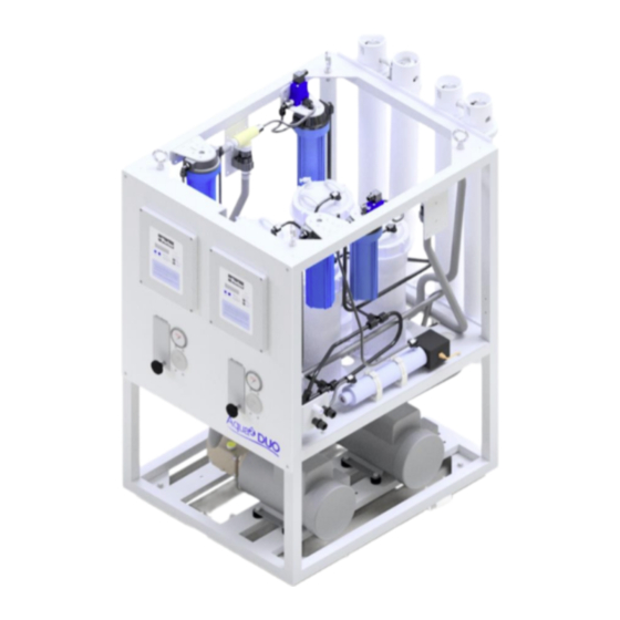
- Page 1 AQUA DUO – A455C (2800 – 6800 GPD) Technical Manual Parker – Water Purification 2630 E. El Presidio Street Carson, CA 90810 www.parker.com/waterpurification...
- Page 2 REVISION HISTORY DESCRIPTION DATE AUTHOR March, 2022 INITIAL RELEASE DIAGRAM AND DRAWING October, 2022 OM & JT UPDATES The following are the types of flags used in this technical manual. They designate safety related items and important operational instructions and should be given special attention when they appear in the text: Text formatted in this manner concerns an operating procedure or practice that, if not WARNING strictly observed, can result in injury to personnel or loss of life.
-
Page 3: Table Of Contents
TABLE OF CONTENTS Contents SYSTEM DESCRIPTION: .................. 5 1.1. SYSTEM SPECIFICATIONS: ..............5 1.2. UTILITY REQUIREMENTS ................. 5 1.3. RECOMMENDED SPARE PARTS LIST ............. 6 1.4. SPECIAL TOOLS LIST ................6 PHYSICAL CHARACTERISTICS ………………………………………...…….7 1.5. PRE-INSTALLATION NOTES ................9 PRECAUTIONS ................... 9 RO SYSTEM LOCATION ................ - Page 4 System Operation Notes................48 Operation Cautions ..................48 Startup Procedure ..................49 High/Low Pressure Fault Lamp Explanation ..........49 Controller Operations ................50 MAINTENANCE & REPAIR................53 GENERAL ....................53 MICRON FILTER ELEMENT REPLACEMENT ......... 53 TROUBLESHOOTING ..................54 System Shuts Down During Operation ............54 Product Water Flow and Product Water Quality ........
-
Page 5: System Description
1.0 SYSTEM DESCRIPTION: 1.1. SYSTEM SPECIFICATIONS: PART VOLTAGE PRODUCT PRODUCT MEMBRANE NUMBER 50/60 HZ - 1/3PH CAPACITY CAPACITY WEIGHT WEIGHT GPD/LPD GPH/LPH A455C-2800 110/220/380/440 2800 GPD 117 GPH 570 lbs. lbs. (10599 LPD) (441 LPH) (258 kg) 2724011333 (269 kg) A455C-3600 110/220/380/440 3600 GPD... -
Page 6: Recommended Spare Parts List
DESCRIPTION CONNECTION 1010 1011 1012 Table 1.2: TIE CONNECTIONS System Single Unit Operation of Single Unit Operation of HP Pump Booster Pump A455C-2800 2.5 HP / 1.84 kW 0.5 HP / 0.37 kW [Horsepower/Kilowatts] [Horsepower/Kilowatts] A455C-3600 2.5 HP / 1.84 kW 2 HP / 1.47 kW A455C-4400 5 HP / 3.68 kW... -
Page 7: Physical Characteristics
1.5. PHYSICAL CHARACTERISTICS: INCHES [MILIMETER] Figure 1.0: 2800-3600 GPD RO System Dimensions Figure 1.1: 4400 & 5800 GPD RO System Dimensions... - Page 8 Figure 1.2: 5200 & 6800 GPD RO System Dimensions Figure 1.3: Mounting and Lifting lugs Dimensions of RO System...
-
Page 9: Pre-Installation Notes
2.0 PRE-INSTALLATION NOTES 2.1 PRECAUTIONS Reverse Osmosis (RO) System storage prior to uncrating: CAUTION DO NOT store in direct sunlight. DO NOT store above 103 degrees F (39 degrees C). DO NOT freeze. CAUTION If the RO system has been shipped new with Reverse Osmosis Membrane Elements installed, the System must be commissioned within 3 months. -
Page 10: Installing The System
Parker Hannifin warranty. Make the following plumbing connections to the RO unit's piping interfaces provided on the General Arrangement drawing. - Page 11 CAUTION Avoid connecting the inlet piping to any water line that services any other piece of equipment. Air could be drawn through the RO unit causing damage to the RO unit's pumps. Any air suction leaks coming into the system feed line may cause the system to shut down due to low feed pressure.
-
Page 12: Components
COMPONENTS All components supplied by Parker, both standard and optional, are described in this section along with items required or desired by the installer. The location, operation, and purpose of each major component are briefly explained in this section. - Page 13 Figure 2.3: Illustration of Unit A and Unit B Controls Components List: CALLOUT DISCRIPTION FUNCTION AWPC-1 & AWPC-2 MAIN CONTROLLER CONTROLS OPERATION OF UNIT BOOSTER PUMP MOTOR ASSY FOR PROVIDES INLET PRESSURE TO UNIT BP-1 UNIT A BOOSTER PUMP MOTOR ASSY FOR PROVIDES INLET PRESSURE TO UNIT BP-2 UNIT B...
- Page 14 Optional 20-MICRON PRE-FILTER- FOR REMOVES PARTICLES LARGER THAN 20- FIL-3 UNIT A MICRONS Optional 20-MICRON PRE-FILTER- FOR REMOVES PARTICLES LARGER THAN 20- FIL-4 UNIT B MICRONS FWF-1 FRESH WATER FILTER- FOR UNIT A REMOVES CHLORINE FWF-2 FRESH WATER FILTER- FOR UNIT B REMOVES CHLORINE HIGH PRESSURE PUMP MOTOR ASSY- PROVIDES MEMBRANES WITH HIGH...
- Page 15 Figure 2.4: Piping and Instrumentation Diagram 2800-3600 GPD...
- Page 16 Figure 2.5: Piping and Instrumentation Diagram 2800-3600 GPD (with Optional 20-Micron Prefilter)
- Page 17 Figure 2.6: Piping and Instrumentation Diagram 4800-6200 GPD...
- Page 18 Figure 2.7: Piping and Instrumentation Diagram 4800-6200 GPD (with Optional 20-Micron Prefilter)
-
Page 19: Mounting Components
MOUNTING COMPONENTS Mounting and plumbing components Inlet and discharge interconnecting lines should be constructed of a NON- FERROUS material. Examples of some suitable materials are PVC, copper-nickel, 316 stainless steel pipe or a reinforced non-collapsing hose. Figure 2.8: Component & TIE Point Connection Callouts... - Page 20 1) Sea Strainer (ST-1 & ST-2) - Optional: This filter helps protect the RO system by removing large particles and debris coming in from seawater. Parker recommends mounting a sea strainer BELOW the vessel’s waterline. The strainer can be installed before or after the Feed Water Inlet as long as it is below the waterline.
- Page 21 2) Media Filter (MMF-1 & MMF-2) - Optional: Parker Recommends installation of the Optional Media filters to remove larger and unwanted particles, thus increasing the system’s lifespan. The location of the Media Filter assembly is installed after the booster pump. The media filter assembly Kit includes the Media filters, the media filter skid/frame, and the plumbing required to plumb with the booster pump.
- Page 22 3) Aqua Duo Frame: The frame holds all the major components of unit A & B . Figure 2.13: Main frame Assembly 4) Automatic Fresh Water Flush (FWF-1 & FWF-2) : This assembly includes a Carbon Filter and an automatic, motor-actuated flapper style Valve that automatically flushes the System with Fresh Water.
- Page 23 Figure 2.14: Freshwater Flush Filter (FWF-1 & FWF-2) Figure 2.15: Freshwater Flush & Check Valve Assemblies • Fresh Water Flush 2-way Solenoid Valve : Automatically actuates at System shut down (and at a preset frequency, in days) to flush the system with Fresh Water.
- Page 24 • Fresh Water Flush Check Valve (CV-1 & CV-2) : Prevents Feed Water from entering the freshwater line. Figure 2.16: Check Valve (CV-1 & CV-2) Assembly • Fresh Water Flush Carbon Filter : Removes chlorine (if present) in the Fresh Water, prior to flowing through the RO Membrane Element.
- Page 25 SINGLE/THREE PERMEATE GPD VOLTAGE BOOSTER PUMP PHASE PART NUMBER SINGLE 2800 - 3600 GPD 110/230 AC/50/60 Hz B016080026 THREE PHASE 2800 - 3600 GPD 208/460 AC/50/60 Hz B016080027 SINGLE 4400 - 6200 GPD 115/230 AC/50/60 Hz B016600005 THREE PHASE 4400 - 6200 GPD 380/460 AC/50/60 Hz B016510001 Table 2.2: Booster Pump Spec...
- Page 26 Figure 2.19: 5-Micron Prefilter Assembly Caution: Do not use third party prefilter elements; use only PARKER Prefilter Elements. Third party prefilter elements on the market do not properly fit, the seams fall apart, they will allow by-pass, and will allow the R.O.
- Page 27 8) Charcoal Filter (Included) : Helps Removes organic compounds and orders (if present) from Product Water. The water flows directly from the product output at the Manifold to the filter. Figure 2.20 : Charcoal Filter (CF1 & CF2) assembly The charcoal filter should be replaced every 3 to 4 months. If a sulfurous (rotten egg) odor is found in the product water or while changing the filter, increase the replacement frequency.
- Page 28 10) High Pressure Pump and Motor Assembly (Included): The High-Pressure Pump Assembly provides high pressure to the vessel membranes to produce potable water. Figure 2.22: High Pressure Pump and Motor Assembly High Pressure Pumps: SINGLE/THREE PERMEATE GPD VOLTAGE HIGH PRESSURE SINGLE/THREE PHASE PUMP PART...
- Page 29 LOW-PRESSURE TRANSDUCER FLOWMETER HIGH-PRESSURE FLOWMETER VALVE TRANSDUCER Figure 2.23: Manifold Assembly 12) Vessel assembly: Located at the back of the frame. The vessel assembly allows the membrane filters to be pressurized to create potable water. The vessel assembly can be relocated from the frame and mounted separately.
- Page 30 13) Power Panel Assembly: Provides necessary voltage and power to the control panel and motors of a unit. The power panel assembly is located on the side of the frame. It is only apparent on higher capacity systems (4400-6800 GPD). A high-capacity Aqua Duo system contains two separate Power panel assemblies for each unit (A &...
-
Page 31: Electrical Connections
50% more than the operating amps shown on the serial number tag. Verify all power switches and power sources are in the OFF position. AC POWERED 110V/220V: Connect RO unit motor to vessel circuit breaker. Parker recommends use of an amp fuse or circuit breaker. - Page 32 Connect all inlet feed lines with the supplied Inlet Suction Hose: Outlet of Inlet of Sea Cock Valve Sea Strainer (Optional) Sea Strainer (Optional) Inlet 3-Way Clean/Rinse Valve (Optional) Inlet 3-Way Clean/Rinse Valve (Optional) Rinse/Clean bucket or container Inlet 3-Way Clean/Rinse Valve (Optional) Booster Pump Booster Pump Media Filter (Optional)
- Page 33 Figure 2.28: Hose & Tube Connection Instructions Figure 2.29: Tubing Fitting Internals...
- Page 34 Connect Brine Discharge line with the supplied Brine Discharge tubing: Outlet of Inlet of System Brine Discharge - TIE 1003 Thru Hull Discharge fitting Connect Product Water line with the supplied nylon tubing: Outlet of Inlet of Potable Product Water from System – Potable Water Storage Tank TIE 1002 &...
-
Page 35: Theory Of Operation And General Description
3.0 THEORY OF OPERATION AND GENERAL DESCRIPTION REVERSE OSMOSIS THEORY Reverse osmosis, like many other practical scientific methods, has been developed from processes first observed in nature. Osmosis is a naturally occurring phenomenon in which a semi-permeable membrane separates a pure and a concentrated solution (a semi-permeable membrane is defined as one that preferentially passes a substance). -
Page 36: Product Water Quality Standards
35,000 ppm (parts per million) TDS, although variations of 5000 ppm are common in various parts of the world. The fundamental goal any desalination process is a significant reduction in the number of dissolved solids in water. Figure 3.2: Simplified Schematic of a RO System It should be noted that no system can remove all the dissolved solids from seawater. -
Page 37: Factors Affecting Permeate Production
(near river mouths or in estuaries). The operator can do this by controlling system pressure manually via the back-pressure regulator valve, located in the system brine piping. For long pump life and low membrane fouling, Parker recommends that 9 psi is not exceeded except in situations of extreme low temperature feed water. -
Page 38: Temperature Correction Factor
CAUTION Operating the unit at more than 120% of rated capacity in low salinity water can damage the membranes and will void the RO unit warranty. TEMPERATURE CORRECTION FACTOR As previously described, the output capacity of any RO unit is highly dependent on feedwater temperature. -
Page 39: Controls And Instrumentation
Measure raw water temperature and determine the corresponding correction factor from Table 4.2 based on the measured temperature. Note the actual product flow rate at the Product Flow meter or digital product readout. Multiply the actual product flow meter flow rate by the correction factor from Table 4.2 to give theoretical temperature compensated flow under standard conditions (25°C). -
Page 40: Product Monitoring System
pressure required for optimal system recovery. The pressurized feedwater then flows directly into the membrane pressure vessels (array). The membrane array is an arrangement of fiberglass pressure vessels each containing RO membrane elements. The pressurized feedwater flows along the membrane elements where reverse osmosis takes place. The feedwater flow is divided into two streams - the high purity product stream (referred to as the product) and the increasingly concentrated reject stream (referred to as the reject). -
Page 41: Commissioning
Figure 3.3 – Human-Machine Interface (HMI)/Controller COMMISSIONING COMMISSIONING CHECKLIST 1. Inspect - Make sure all external plumbing connections are made per the P&ID diagram. Make sure all electrical connections to all external devices are connected properly per the electrical schematics. 2. - Page 42 NOTE Some systems are shipped WITHOUT the RO Membrane Element. This is to accommodate, for example, boat builders who install the system well in advance of commissioning the boat and the Parker Hannifin System. If the RO Membrane Element has been installed, there will be an Element Serial Number tag attached to the RO Membrane/Vessel Assembly.
- Page 43 Failure to properly flush and/or store the system will lead to premature fouling or drying out of the RO Membrane Element, which is not covered by the Parker Hannifin Warranty and is the liability of the person commissioning the system.
-
Page 44: Pressure Changes
c) If the system will not be operated within the next two months or longer, perform a long-term storage operation. The freshwater flush cycle will last for approximately 10 minutes. After the freshwater flush cycle is complete, the freshwater flush lamp will illuminate and intermittently blink in the stand-by mode. - Page 45 The feed water temperature is higher than 77º F/ 25º C. The feed water salinity is less than 35,000 PPM TDS (3.5% Total Dissolved Solids). The RO Membrane Element is new and on the plus 15% side of the specifications. By monitoring feed water salinity, temperature and resulting system operating pressure, it is possible to measure and monitor the fouling of the RO Membrane Element over time and use.
- Page 46 PARKER HANNIFIN AQUA DUO UNIT A INITIAL READINGS At the time of commissioning the NEW system, record the following information after one hour of continuous proper operation of the system. Retain this form in the Owner’s Manual for future reference and troubleshooting.
- Page 47 PARKER HANNIFIN AQUA DUO UNIT B INITIAL READINGS At the time of commissioning the NEW system, record the following information after one hour of continuous proper operation of the system. Retain this form in the Owner’s Manual for future reference and troubleshooting.
-
Page 48: Operations
OPERATIONS System Operation Notes The freshwater production of the Aqua DUO Desalination System models depends on six factors: • Feed Water Temperature • Feed Water Salinity • Feed Water Flow Rate • Operating Pressure • Characteristics of the individual RO Membrane Element •... -
Page 49: Startup Procedure
Startup Procedure Open the Sea Cock Valve fully. Switch the electrical power to the system on at the circuit breaker. The “POWER” lamp on the system Touch Pad will illuminate. Ensure that the back-pressure regulator valve is fully open (counterclockwise). This is not required and is commonly skipped on systems equipped with a Remote Control. -
Page 50: Controller Operations
122°F / 50°C. High temperatures will cause structural damage to the RO Membrane Element. If any abnormality develops, turn off the unit and troubleshoot the problem. Check for unusual noises or other occurrences. Controller Operations Figure 5.1: Controller Interface Start/Stop button Powers on and sets the system in its initial state. - Page 51 FWF, running, FWP); and timers. Press the CYCLE button once to view this menu and CYCLE again to scroll through the menu items. Every time CYCLE is pressed, the next item is shown. If you release, and do not push the CYCLE button for more than 5 seconds, you will return to the main screen.
- Page 52 FWF Interval – FWF interval time (HH:mm:ss) PassiveUVoff – Time from leaving freshwater production to turning UV off (HH:mm:ss) UV off delay – Time from UV on to diversion valve to tank (HH:mm:ss) AutoStart Tank – Autostart on tank empty (yes or no) BP Delay –...
-
Page 53: Maintenance & Repair
6.0 MAINTENANCE & REPAIR 6.1 GENERAL The service life of most of the system equipment is directly related to the raw water inlet conditions. Improper maintenance will also significantly reduce the life expectancy of the major unit components (such as the membranes, filters, and pumps) as well as the reliability of the unit. -
Page 54: Troubleshooting
Detail and record everything happening with the system. Read Chapter 7 of the manual, see if some of the problems listed and the solutions applies to the commissioned system. Parker’s technical support team can help you if there are any further questions. - Page 55 Another cause may be an air suction leak at or prior to the Booster Pump (suction line at or prior to the Inlet of the Booster Pump). Within up to 10 minutes of operation, if the Low- Pressure Gauge gradually decreases to near or below 6 PSI, check the inlet line and associated components prior to the Boost Pump Inlet: •...
-
Page 56: Product Water Flow And Product Water Quality
Product Water Flow and Product Water Quality “The system is operating at 850 psi and is not producing specified product water flow.” Feed Water salinity is greater than 35,000 PPM: Higher salinity Feed Water Requires higher pressure to make rated flow. Refer to Salinity Effects in Chapter 3 to identify expected pressure for Higher salinity feed waters. - Page 57 blockage in the Product Water Line during operation 3. Cracked End Plug in the High-Pressure Vessel allowing seawater to mix with Product Water which is caused by over tightening of tapered pipe fittings into the End Plug 4. Damaged or worn Product Water O-ring in the High-Pressure Vessel End Plug 5.
-
Page 58: 3-Way Product Water Diversion Valve Abnormalities
• Charcoal Filter element is fouled, replace element • pH Neutralizer element is fouled, replace element. • 3-way Product Water Diversion Valve is blocked, or inner ports are out of adjustment, adjust inner ports. There is a Sulfurous odor (rotten eggs) in the product tank. 1. - Page 59 water and the valve’s solenoid coil is not defective, the valve’s solenoid coil is warm or hot to the touch, however the Diversion Valve does not divert potable water to the post filtration section and on to the boat’s potable water storage tank. The Diversion Valve internal ports may have been moved by over tightening of the black tube fittings causing blockage internally and require adjustment.
-
Page 60: Booster Pump Abnormalities
• Repair the pump with a Seal Kit. If the High-Pressure Pump electric motor fails to operate, follow these steps to isolate the problem: 1. Ensure that the system is receiving proper power from the power source. 2. Press “Start” switch to activate the motor. It will take approximately 10 seconds before the High-Pressure Pump Motor starts. - Page 61 may be bad. Replace the contactor. 9. If 12V DC is not present when the Booster Pump is activated, trace the yellow and yellow/black wires to the Control Printed Circuit Board and measure the DC voltage at the terminals. It should read 12V when activated. Electrical and Electronic Circuit Abnormalities The Start Switch is pressed, but the system does not attempt to start.
- Page 62 replace it. Product Water 3-way Diversion Valve does not switch to “safe water,” potable water. 1. First see "3-WAY PRODUCT WATER DIVERSION VALVE ABNORMALITIES" in part C, Chapter 7. 2. The Water Quality greater than 1000ppm the 3-way Product Water Diversion Valve is not energized;...
- Page 63 High-Pressure Pump; the maximum oil level is at the top of the sight glass window. Use only Parker High Pressure Pump oil. DO NOT USE MOTOR OR OTHER HYDRAULIC OIL.
- Page 64 8 . DRAWINGS & DIAGRAMS...
- Page 65 P&ID:...
- Page 69 GA Drawing:...
- Page 75 ASSY NUMBER VOLTAGE MEDIA PERMEATE CAPACITY HP MOTOR HP PUMP BOOSTER BOOSTER PUMP MEMBERANE DRY WT lbs WET WT lbs FILTER MOTOR ASSEMBLY A455C-2800 110/220AC 50/60Hz 1/3PH 0151010 2800 15AC062412 81012026 1519081110 1221515772 4x 2724011333 570 (258 kg) 591 (269 kg) A455C-3600 110/220AC 50/60Hz 1/3PH 0151010...
- Page 76 ELEMENT CPFE 5 MIC 32.5 SQFT 0803004773 ELEMENT,CHARCOAL,2.5 x10.0 10181421CC GAUGE 0-1400 CBM.O-RING SEAL 10181522CC GAUGE -30-0-70 CBM.NPT 85012027 KNOB,PARKER,ROUND,BLK 1401095998 SOLENOID VALVE EXTERNAL PORT 1401096100 VALVE SOLENOID 12VDC 2317100200 TRANSDUCER 0-200 PSI .437 SAE 3131680298 PLUG CONNECTOR DIN 3-PIN H2510210001 FLOW METER.5-5GPM &...
- Page 77 4 - Wiring Diagrams...
Need help?
Do you have a question about the AQUA DUO - A455C and is the answer not in the manual?
Questions and answers