Table of Contents
Advertisement
Quick Links
Installation and Operating Instructions
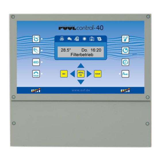
POOL-Control-40
Filter control unit with built-in level control
Dimensions:
Operating voltage:
Power consumption of control unit:
Switching capacity:
Degree of protection:
Level sensors:
Ambient temperature:
Air humidity:
Part no. 310.000.0560
Technical data
300mm x 285mm x 85mm
approx. 5VA (depends on
Pump:
Heating:
Dosing system:
Auxiliary output:
Safety Extra Low Voltage (SELV)
Connectable pumps
230V alternating-pump
(rated current max. 8A)
400V three-phase pump
(rated current max.8A)
Speck ECO-Touch-Pro pump
Speck Badu-90-ECO-VS pump
Speck Badu-90-ECO-Motion pump
Pentair IntelliFlo pump
Pentair SuperFlo pump
Zodiac FloPro VS pump
UWE PMM pump
400V/50Hz
operating mode)
max. 8A / 3.0 kW (AC3)
max. 3A / 0.4 kW (AC3)
max. 3A / 0.4 kW (AC3)
max. 3A / 0.4 kW (AC3)
IP 40
0-40°C
0-95% non-condensing
Advertisement
Table of Contents

Related Manuals for OSF POOL-Control-40


Summary of Contents for OSF POOL-Control-40
-
Page 1: Installation And Operating Instructions
Installation and Operating Instructions POOL-Control-40 Filter control unit with built-in level control Part no. 310.000.0560 Connectable pumps 230V alternating-pump (rated current max. 8A) 400V three-phase pump (rated current max.8A) Speck ECO-Touch-Pro pump Speck Badu-90-ECO-VS pump Speck Badu-90-ECO-Motion pump Pentair IntelliFlo pump... -
Page 2: Table Of Contents
Operating instructions for Pool control-40 filter control unit Page: 2 (24) Contents Installation and Operating Instructions ................1 Technical data ........................1 Contents ..........................2 Function ..........................5 Installation ........................... 5 Electrical connection ......................5 Low-voltage lines ...............................6 Connecting the power supply for a 400V three-phase pump ................6 Connecting the power supply for a 230V single-phase AC pump ..............6 Connecting the power supply for a 230V pump (with electronic motor protection enabled) ......7 Connecting the power supply for a Speck ECO-Touch-Pro pump ..............7... - Page 3 Operating instructions for Pool control-40 filter control unit Page: 3 (24) Fuses ..........................14 Controls on the front panel ....................15 Control unit ON/OFF............................16 Manual operation ............................16 Reset fault indicator ............................16 ECO ON/OFF ..............................16 Pump indicator light ............................16 Heating indicator light .............................
- Page 4 Operating instructions for Pool control-40 filter control unit Page: 4 (24) Use main drain ............................22 Level control ..............................22 Type ................................22 Time limit ..............................22 Minimum switching interval ......................... 22 Switch-on delay ............................22 Switch-off delay ............................22 Auxiliary output ...............................
-
Page 5: Function
Operating instructions for Pool control-40 filter control unit Page: 5 (24) Function PC-40 control unit lets you time the on/off cycles of a filter pump based on a user-programmable daily or weekly schedule. A 400V 3-phase pump, a 230V single-phase AC pump or a variable-speed filter pump may be used as the filter pump (see wiring diagrams). -
Page 6: Low-Voltage Lines
Operating instructions for Pool control-40 filter control unit Page: 6 (24) must be used and the relevant regulations observed. Always disconnect the unit from the power supply before opening the case. All electrical wiring and calibration and servicing work must be performed solely by an approved electrician. -
Page 7: Connecting The Power Supply For A 230V Pump (With Electronic Motor Protection Enabled)
Operating instructions for Pool control-40 filter control unit Page: 7 (24) Connecting the power supply for a 230V pump (with electronic motor protection enabled) If a 230V pump is meant to be monitored by the electronic motor protection device, the option Filter pump - type: 3-phase pump must be selected for the filter pump. -
Page 8: Connecting The Power Supply For A Zodiac Flopro Vs Pump
Operating instructions for Pool control-40 filter control unit Page: 8 (24) Connecting the power supply for a Zodiac FloPro VS pump A Zodiac FloPro VS pump can be connected directly to the PC-40 unit. Connect the speed controller to terminals 6-13. A separate mains power supply must be provided for the pump. -
Page 9: Connecting The Power Supply For A Uwe Pmm Pump
Operating instructions for Pool control-40 filter control unit Page: 9 (24) Connecting the power supply for a UWE PMM pump A UWE PMM pump can be controlled by the PC-40. The power supply for the pump must be separate from the power supply and cannot be provided by the PC-40. -
Page 10: Connecting The Slide Valves For Backwashing
Operating instructions for Pool control-40 filter control unit Page: 10 (24) Connecting the slide valves for backwashing A 230V slide valve for the backwash function can be connected to the terminals U10 and N. A 230V slide valve for the rinsing function can be connected to the terminals U11 and N. Both valves are controlled by the internal backwash controller. -
Page 11: Connecting A Fault Indicator
Operating instructions for Pool control-40 filter control unit Page: 11 (24) Connecting a fault indicator An external fault indicator can be connected to volt-free floating terminals 19 and 20. This contact is rated for a maximum load of 230V/4A. Connecting a flow sensor A flow sensor or a pressure sensor can be connected between terminals 21 and 22 instead of the factory-fitted link, to provide additional protection for the pump against dry-running. -
Page 12: Level Control
Operating instructions for Pool control-40 filter control unit Page: 12 (24) Level control The built-in level control is designed both for overflow pools with spillway and for skimmer pools. The version to be used must be specified when configuring the control unit before use: in the configuration menu select either the option Level control - type: collect. -
Page 13: Pools With Skimmer
Operating instructions for Pool control-40 filter control unit Page: 13 (24) off the filter pump to prevent it being damaged by running without water. As soon as the water level has returned to the height of the "Dry-running protection / pump ON" probe (terminal 37) and touches this probe, the level control system automatically switches the filter pump back on. -
Page 14: Temperature Sensor
Operating instructions for Pool control-40 filter control unit Page: 14 (24) Temperature sensor Pool temperature sensor Connect the swimming-pool temperature sensor to terminals 29 and 30. The temperature sensor is supplied as standard with a cable length of 1.5m. If required, this can be extended to a maximum length of 20m using a twin-core cable (min. - Page 15 Operating instructions for Pool control-40 filter control unit Page: 15 (24) Controls on the front panel Backwash indicator light Solar heating indicator light Heating indicator light Water input indicator light Filter pump indicator light ON/OFF Temperature selection Manual/Automatic Timer programming „ECO“...
- Page 16 Operating instructions for Pool control-40 filter control unit Page: 16 (24) This button can be used to switch the entire control unit on and off. Control unit Caution! This does not disconnect the control unit from the power supply ON/OFF This button is illuminated when the control unit is on.
- Page 17 Operating instructions for Pool control-40 filter control unit Page: 17 (24) day of the week flashes. 2. Use the buttons to select whether you want to set the day, hour or minutes. The relevant text flashes. 3. Use the buttons to make the setting for the currently flashing text (day, hour or minutes).
- Page 18 Operating instructions for Pool control-40 filter control unit Page: 18 (24) number in the top right) 3. Press the button. The day of the week flashes. 4. Use the buttons to change the setting for the currently flashing text. To clear the setting, select "not progr." (short for "not programmed").
- Page 19 Operating instructions for Pool control-40 filter control unit Page: 19 (24) Press the button. ECO mode Use the buttons to scroll through the menu until the display shows "ECO mode". Press the button again to select ECO mode. Press the button to program the timer settings (see procedure Timer described under Timer programming)
- Page 20 Operating instructions for Pool control-40 filter control unit Page: 20 (24) Press the button. Solar heating Use the buttons to scroll through the menu until the display shows "solar heating". Press the button to select the solar heating settings. Press the button.
- Page 21 Operating instructions for Pool control-40 filter control unit Page: 21 (24) Press the button. Frost protection Use the buttons to scroll through the menu until the display shows "Frost protection". Press the button to select the frost protection settings. Press the button.
- Page 22 Operating instructions for Pool control-40 filter control unit Page: 22 (24) Press the button to use the buttons to set how long the filter pump should stop running whenever the slide valves are operated. Press the button to save the setting. Adjustment range 0 to 120s, factory setting 0s Use the buttons to scroll through the backwashing...
- Page 23 Operating instructions for Pool control-40 filter control unit Page: 23 (24) (when using a mini float switch as a sensor). Adjustment range 10 to 30s, factory setting 0s Press the button. Auxiliary output Use the buttons to scroll through the menu until the display shows "auxil.
- Page 24 Relax and enjoy your swimming pool! Further information can be found on the Internet at the following address: https://osf.de/download/documents/documents.php?device=PC-40 Hansjürgen Meier Elektrotechnik und Elektronik GmbH & Co KG Eichendorffstraße 6 D-32339 Espelkamp Email: info@osf.de Internet: www.osf.de Subject to changes 04/2021...
Need help?
Do you have a question about the POOL-Control-40 and is the answer not in the manual?
Questions and answers