Table of Contents
Advertisement
Quick Links
Installation and operating manual
400V filter control unit
Dimensions:
Operational voltage:
Control system power consumption:
Switching capacity:
Protection class:
Surrounding
temperature
Humidity:
Item No.: 3100000440
Specifications:
220mm x 220mm x 100mm
Pump:
Heater:
Dosing system:
max. 80% rel. F., non-condensing!
-250
400V/50Hz
ca. 10VA
max. 3.0 kW (AC3)
max. 2A
max. 8A
IP 40
0-40°C
Advertisement
Table of Contents

Related Manuals for OSF POOL-Control-250


Summary of Contents for OSF POOL-Control-250
- Page 1 Installation and operating manual -250 400V filter control unit Item No.: 3100000440 Specifications: Dimensions: 220mm x 220mm x 100mm Operational voltage: 400V/50Hz Control system power consumption: ca. 10VA Switching capacity: Pump: max. 3.0 kW (AC3) Heater: max. 2A Dosing system: max.
-
Page 2: Table Of Contents
PC-250 Filter control unit operating manual Page: 2 (24 Contents Function: ............................... 4 Front panel displays and controls: ....................... 5 LCD display ..............................5 Selecting operating mode ..........................5 Pump indicator lamp ............................6 Heater indicator lamp ............................. 6 Solar heater ..............................6 Backflushing process indicator lamp ...................... - Page 3 PC-250 Filter control unit operating manual Page: 3 (24 Set temperature ............................. 15 Current ................................15 Motor protection ............................15 Solar difference ............................. 15 Solar additional temperature ........................16 Limit temperature ............................16 Additional heater minimum time (hysteresis) .................... 16 Solar heater minimum time (hysteresis) .....................
-
Page 4: Function
PC-250 Filter control unit operating manual Page: 4 (24 Function: PC-250 filter control unit enables enable convenient automatic regulation of time-dependent switching on and off of a the swimming pool water level. The filter 400 V three-phase current pump or a 230 pump is also additionally protected against alternating current... -
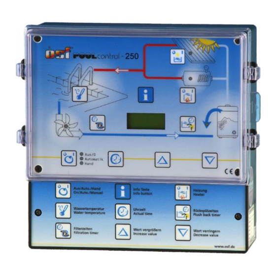
Page 5: Front Panel Displays And Controls
Front panel displays and controls: solar button ON/OFF control light solar heating control light heating heating ON/OFF adjust temperature info Button adjust switching times control light backflushing control light filter pump adjust backflushing select operating mode control lights operating mode adjustment buttons set time LCD display... -
Page 6: Pump Indicator Lamp
PC-250 Filter control unit operating manual Page: 6 (24 Pump indicator lamp This indicator lamp displays filter pump operation. You can see the pump operating mode from the lamp colour: Off: the filter pump is switched off Green: the filter pump is in operation Red: the pump has been temporarily switched off by the NR-12-TRS-2 level regulation system or the EUROTRONIK-10 backflushing system, the motor protection has triggered or it was switched off by phase fields. -
Page 7: Setting The Time
PC-250 Filter control unit operating manual Page: 7 (24 Setting the time Use the key to set the current time: Sa 14:46 key the display shows Uhrzeit 1. Press the , the minute display blinks. 2. You can now use the keys to set the minutes. -
Page 8: Programming Backflushing
PC-250 Filter control unit operating manual Page: 8 (24 to delete them. 1. Press the key as often as required until the switching time to be 10:00 16:00 deleted is displayed 2. The switching time is deleted if you press the keys simultaneously. -
Page 9: Installation
PC-250 Filter control unit operating manual Page: 9 (24 The current language is displayed. If you press the keys, you can switch between the German and English languages. The language displayed will be saved automatically. 2) Solar temperature 3) Water temperature 4) Filter pump operating status 5) Additional heater operating status 6) Solar heater operating status... -
Page 10: Mains Connection When Using 400V 3-Phase Pump
PC-250 Filter control unit operating manual Page: 10 (24 Mains connection when using 400V 3-phase pump: Pool-Control-250 Vorsicherungen max. B16A Wicklungs- schutz- kontakt FI-Schalter 25A/0,03A Filterpumpe 400V max. 8A Netz 3/N/ 400/230V 50Hz The bridge fitted in the works between the terminals labelled WSK must be removed if a pump with coil earthing contact is connected. -
Page 11: Level Regulation And Backflushing Control
PC-250 Filter control unit operating manual Page: 11 (24 The floating relay contact between terminals 22 and 23 can be loaded with a voltage of maximum 230 V and a current of maximum 8 A. If the heater requires 230 V, it can be connected to terminal U2. Terminals are also available for the heater N connection. -
Page 12: Dosing System Connection
PC-250 Filter control unit operating manual Page: 12 (24 Dosing system connection There is a floating relay contact between terminals 20 PC-250 and 21. This can, for example, be used for activation of 20 21 the dosing system (the contact remains closed during filter operation). -
Page 13: Balancing The Temperature Controller
16A on site. Service terminal An osf service terminal (Art. No. 3010000900) can be connected to this control system for optimum control system settings for a wide range of swimming pool equipment and for assisting in initial startup and fault diagnosis. -
Page 14: Filter Unit Operating Mode
PC-250 Filter control unit operating manual Page: 14 (24 Further lines can be called up using the keys. Values in the top line can be changed by pressing the key if necessary. Filter unit operating mode This line displays the current filter unit operating mode. The following displays are possible: Control system off Use the... -
Page 15: Water Temperature
Solar temperature Water temperature The current collector temperature is The current water temperature is displayed in this line. If the display displayed in this line. If the display does not agree with the actual does not agree with the actual temperature, it can be readjusted temperature, it can be readjusted using the adjuster on the printed... -
Page 16: Solar Additional Temperature
PC-250 Filter control unit operating manual Page: 16 (24 Once the key has been pressed, the filter unit is switched off and the display shows the following: Solardiff.: ° Differenztemp. zwischen Wasser und Kollektor 2. Now use the keys to change the temperature difference. The smallest adjustable value is 0.5°, the largest 10°. -
Page 17: Solar Heater Minimum Time (Hysteresis)
PC-250 Filter control unit operating manual Page: 17 (24 adjusted to meet the requirements of the relevant heater equipment if it is displayed in the top line: 1. Once the key has been pressed, the filter unit is switched off and the display shows the following: Min.Heizen: Minimale... -
Page 18: Heater Priority Circuit
PC-250 Filter control unit operating manual Page: 18 (24 Heater priority circuit This line displays whether the temperature regulation system has priority over the filter time settings. Using the priority circuit, the filter pump can be switched on by the temperature regulation system even outside the set filter times. -
Page 19: Frost Protection
PC-250 Filter control unit operating manual Page: 19 (24 The following lines are used for manual activation of the output relay. Frost protection This line displays the current frost protection function switch-on temperature. This value can be adjusted to meet the requirements of the relevant filter unit if it is displayed in the top line: 1. -
Page 20: Eurotronik Backflushing Signal
PC-250 Filter control unit operating manual Page: 20 (24 Forced switch-on ON Forced switch-on requested, or terminals 11 and 12 connected. EUROTRONIK backflushing signal This line displays whether the EUROTRONIK-10 switches the filter pump on during backflushing or rinsing. The following displays are possible: EUROTRONIK OFF no switch-on command from EUROTRONIK EUROTRONIK ON... -
Page 21: Heater
PC-250 Filter control unit operating manual Page: 21 (24 3. Now you can use the key to switch the filter pump on additionally. Once the filter pump switched following displayed: Solaranlage HANDBETRIEB Stellantrieb: Pumpe: 4. If you press the key again, the normal diagnosis display appears and the filter unit continues to operate. -
Page 22: Rinsing Valve
Diagnosis This menu is only accessible for trained osf service technicians Language When the language is shown in the top line of the service terminal display, you can... -
Page 23: Combination Of Pc-250 With Nr-12-Trs-2 And Eurotronik-10
Combination of PC-250 with NR-12-TRS-2 and Eurotronik-10 11 12 13 14 U1 V1 1 N SKSK L1 L2 L3 N U2 N 20 2130 31 2 3 4 5 2 L1 N U2 U3 10 11 Netz 400V Netz 230V Netz 230V 3/N/PE 1/N/PE... - Page 24 PC-250 Filter control unit operating manual Page: 24 (24...
Need help?
Do you have a question about the POOL-Control-250 and is the answer not in the manual?
Questions and answers