Table of Contents
Advertisement
Quick Links
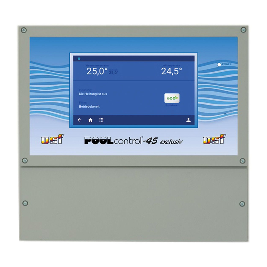
Installation and Operating Instructions
Filter control unit with built-in level control
Dimensions:
Operating voltage:
Power consumption of control unit:
Switching
capacity:
Degree of protection:
Level sensors:
Ambient temperature:
Air humidity:
Memory card:
Internet port:
and LAN port
Part no. 310.000.0580
Technical data
300mm x 285mm x 85mm
(depends on operating mode)
Pump:
Heater:
Dosing system:
Auxiliary output:
12V Safety Extra Low Voltage (SELV)
Compatible pumps
230V single-phase pump
(rated current up to 8A)
400V three-phase pump
(rated current up to 8A)
Speck ECO-Touch-Pro pump
Speck Badu-90-ECO-VS pump
Speck Badu-90-ECO-Motion pump
Pentair IntelliFlo pump
Pentair SuperFlo pump
Zodiac FloPro VS pump
UWE PMM pump
3/N/PE 400V/230V 50Hz
approx.5VA
max. 8A / 3.0 kW (AC3)
max. 3A / 0.4 kW (AC3)
max. 3A / 0.4 kW (AC3)
max. 3A / 0.4 kW (AC3)
IP 40
0-40°C
0-95% non-condensing
Micro SD
LAN
Advertisement
Table of Contents

Related Manuals for OSF POOLcontrol-45 exclusiv


Summary of Contents for OSF POOLcontrol-45 exclusiv
-
Page 1: Technical Data
Installation and Operating Instructions Filter control unit with built-in level control and LAN port Part no. 310.000.0580 Compatible pumps 230V single-phase pump (rated current up to 8A) 400V three-phase pump (rated current up to 8A) Speck ECO-Touch-Pro pump Speck Badu-90-ECO-VS pump Speck Badu-90-ECO-Motion pump Pentair IntelliFlo pump Pentair SuperFlo pump... -
Page 2: Table Of Contents
Operating instructions for POOL-Control-45 exclusiv filter control unit Page 2 (44) Contents Technical data ........................1 Contents ..........................2 Function ..........................5 Installation ........................... 5 Fuses ............................ 6 Electrical connection ......................6 Low-voltage lines ............................... 6 Connecting the power supply for a 400V three-phase pump ................6 Connecting the power supply for a 230V single-phase pump ................ - Page 3 Operating instructions for POOL-Control-45 exclusiv filter control unit Page 3 (44) How level control works for balancing tanks .....................14 Pool with skimmer ............................15 Level measurement in the standpipe ......................15 Use without level control ..........................15 Solenoid valve for topping up the water level ....................15 Display ..........................
- Page 4 Service settings ............................30 Configuring two filtration systems .................. 30 Internet connection ......................32 Using the osf communication server ....................... 32 Communication server for pool owners ................. 33 Registering a new device with the server ....................33 Communication server for pool installers ..............35 Registering a new control unit with the server ..................35...
-
Page 5: Function
Operating instructions for POOL-Control-45 exclusiv filter control unit Page 5 (44) Function PC-45 exclusiv control unit lets you time the on/off cycles of a filtration pump based on a user- programmable daily or weekly schedule. A 400V three-phase pump, a 230V single-phase pump or a variable-speed pump may be used as the filtration pump (see wiring diagrams). -
Page 6: Fuses
Operating instructions for POOL-Control-45 exclusiv filter control unit Page 6 (44) Fuses The electronic controller is protected by a Controller 0.5A microfuse located on the printed circuit board inside the control unit. A Valves separate 3.15A microfuse is provided for each of the following outputs: heating, Heating dosing... -
Page 7: Connecting The Power Supply For A 230V Single-Phase Pump
Operating instructions for POOL-Control-45 exclusiv filter control unit Page 7 (44) Connecting the power supply for a 230V single-phase pump The factory-inserted link between the two terminals 1 and 2 must be removed when connecting a pump fitted with a winding protection switch. If the pump does not have a winding protection switch, the link must remain screwed in place. -
Page 8: Connecting The Power Supply For A Speck Badu-90-Eco-Motion Pump
Operating instructions for POOL-Control-45 exclusiv filter control unit Page 8 (44) Connecting the power supply for a Speck Badu-90-ECO-Motion pump A Speck Badu-90-ECO-Motion pump can be connected directly to the PC-45 exclusiv unit. Connect the speed controller to terminals 10-15. The mains power supply to the pump must be provided separately, not via the PC-45 exclusiv. -
Page 9: Connecting The Power Supply For A Pentair Superflo Vs Pump
Operating instructions for POOL-Control-45 exclusiv filter control unit Page 9 (44) Connecting the power supply for a Pentair SuperFlo VS pump A SuperFlo VS pump can be controlled by the PC-45 exclusiv. The mains power supply to the pump must be provided separately, not via the PC-45 exclusiv. -
Page 10: Connecting The Slide Valves For Backwashing
Operating instructions for POOL-Control-45 exclusiv filter control unit Page 10 (44) Connecting the slide valves for backwashing A 230V slide valve for the backwash function can be connected to terminals U7 and N. A 230V slide valve for the rinsing function can be connected to terminals U8 and N. Both valves are controlled by the internal backwash controller. -
Page 11: Connecting A Fault Indicator
Operating instructions for POOL-Control-45 exclusiv filter control unit Page 11 (44) Connecting a fault indicator An external fault indicator can be connected to volt-free floating terminals 24 and 25. This contact is rated for a maximum load of 230V/4A. Connecting a main drain valve (ECO valve) A main drain valve (ECO valve) or a valve for water extraction from the sides of the pool can be connected to terminals U5 and U5c. -
Page 12: Connecting A Shut-Off Valve (Interlock For The 2Nd Filter)
Operating instructions for POOL-Control-45 exclusiv filter control unit Page 12 (44) Connecting a shut-off valve (interlock for the 2nd filter) A valve can be connected to terminals U6 and U6c. This facility can be used to isolate the filter while another filter is being backwashed. Operation depends on the configuration. This contact is rated for a maximum load of 230V/1A. -
Page 13: Level Control
Operating instructions for Pool control-45 exclusiv filter control unit Page: 13 (44) Level control The built-in level control is designed both for overflow pools with spillway and for skimmer pools. The version to be used must be specified when configuring the control unit before use: in the configuration menu select either the option pool with flow-off gutter or pool with skimmer. -
Page 14: Operation With 5 Probes
Operating instructions for Pool control-45 exclusiv filter control unit Page: 14 (44) Operation with 5 probes Funktion der einzelnen Tauchelektroden automatic actuation ON Automatic actuation operates between these two probes automatic actuation OFF double function: close solenoid valve open solenoid valve double function: Dry-running protection / pump ON In normal mode, the water level... -
Page 15: Pool With Skimmer
Operating instructions for Pool control-45 exclusiv filter control unit Page: 15 (44) Pool with skimmer mini float switch must be used as the sensor for skimmer pools. The float switch lead can be extended with a cable (2x0.75mm²) of up to 30m in length. Please note that the connection must be absolutely watertight. -
Page 16: Display
Operating instructions for Pool control-45 exclusiv filter control unit Page: 16 (44) Display Time and Network Operating light connection date green = ON Heating Water supply red = OFF Filtration pump Back, Cancel without Pro mode / saving Child safety lock Home Home Home... -
Page 17: Switching Off The Pc-45 Exclusiv
Operating instructions for Pool control-45 exclusiv filter control unit Page: 17 (44) Switching off the PC-45 exclusiv The button for switching off the control unit is located on the “Operating mode” display page. Press the “operating mode” button. Press and hold the power-off button for at least 3 seconds to switch off the PC-45 exclusiv. -
Page 18: Heater Settings
Operating instructions for Pool control-45 exclusiv filter control unit Page: 18 (44) To enable the safeguarding function, touch the control bar again with your finger and swipe from right to left. (Note the icon on the left of the status bar). The safeguarding function is re-enabled automatically when no control button has been pressed for an hour. -
Page 19: Automatic - Continuous Running - Off
Operating instructions for Pool control-45 exclusiv filter control unit Page: 19 (44) Automatic – Continuous running – Off Tap the “Filtration timer” button Use this button to switch between the operating modes AUTO OFF. Note the icon on the right. =>... -
Page 20: Checking The Timer Settings
Operating instructions for Pool control-45 exclusiv filter control unit Page: 20 (44) Select the time you want Tap “X” to delete the timer setting. This cannot be undone. Checking the timer settings Tap the “Filtration timer” button The table shows the programmed switching times for the timer Setting the ECO filtration times Tap the “Menü”... -
Page 21: Automatic - Continuous Running - Off
Operating instructions for Pool control-45 exclusiv filter control unit Page: 21 (44) program backwash ECO timer backwash Automatic – Continuous running – Off Tap the “ECO timer” button Use this button to switch between the operating modes AUTO OFF. Note the icon on the right. =>... -
Page 22: Setting Up Party Mode
Operating instructions for Pool control-45 exclusiv filter control unit Page: 22 (44) Use this button to switch between the operating modes AUTO and OFF. Note the icon on the right. AUTO => runs under timer => switched off Tap this button to program the day of the week and time for You can program additional backwash times backwashing. -
Page 23: Fault Indicators / Information Page
This network name can be changed via the communication server IP address ID number for the osf communication server Software version of each circuit board This screen shows the event log. The PC-45 exclusiv records all events and any changes that have been made at the unit. -
Page 24: Service Settings
Operating instructions for Pool control-45 exclusiv filter control unit Page: 24 (44) Service settings Tapping this button in the main screen (bottom right) takes you into the Service area. Only a qualified professional is allowed to make changes to the settings in this area. Set the date and time Network settings (see below “Connecting to the Internet”) -
Page 25: Configuring The Control Unit
Operating instructions for Pool control-45 exclusiv filter control unit Page: 25 (44) Configuring the control unit Pro mode To ensure smooth running of the pool system, when the control unit is first installed it must be configured to suit the actual swimming pool it will be used with. These settings can be altered only in Pro mode, in order to safeguard this configuration from being altered by mistake. -
Page 26: Configuring The Heating
Operating instructions for Pool control-45 exclusiv filter control unit Page: 26 (44) Configuring the heating The type of heating system must be specified when the control unit is first set up for use. The following options are available: heat exchanger ... -
Page 27: Connecting A Filter-Control Plus To The Pc-45 Exclusiv
Operating instructions for Pool control-45 exclusiv filter control unit Page: 27 (44) Connecting a Filter-Control plus to the PC-45 exclusiv The two control units communicate via an Ethernet local area network (LAN). For the control units to work together correctly, they must both be connected to the same local area network. -
Page 28: Establishing Communication Between A Pc-45 Exclusiv And A Filter-Control Plus
The same procedure used for the first filtration circuit must now be used for configuring the second filtration circuit. Disconnecting the Filter-Control plus from the PC-45 exclusiv 1. In the Service menu, press the “osf network cluster“ button. Tap the “Filter Control Plus” button... -
Page 29: Operation (2Nd Filter)
(slide valves) for both filters. Filtration pump 1 Home screen Connection to osf communication server Filtration pump 2 The Home screen of the PC-45 exclusiv also shows the status bar for the second filter. -
Page 30: Service Functions (2 Filters)
Operating instructions for Pool control-45 exclusiv filter control unit Page: 30 (44) Service functions (2 filters) A few Setup menus for service functions have been added to the Home screen. Alarm settings for the 2nd filter Two screens have been added to the “Alarm settings” menu. In this menu, you choose which fault indicators are issued as an acoustic alarm, via email or using the floating relay contact. - Page 31 Operating instructions for Pool control-45 exclusiv filter control unit Page: 31 (44) Backwashing using two pumps Two-filter system in which one filter is backwashed by both pumps simultaneously. Characteristics: When backwashing takes place, the connecting valve opens and the shut-off valve for the other filter closes. One pump for two filters Two-filter system containing one pump.
-
Page 32: Internet Connection
This server is designed for pool owners. Mypool.osf.de The entire pool system including all web-enabled osf products is displayed on one page on the monitor. The key data for all devices can be retrieved with a single tap of a button. -
Page 33: Communication Server For Pool Owners
Once you have personally registered, you can log in and then register your new device in your user profile. Each web-enabled osf control unit has a DEVICE ID (identification number). This DEVICE ID must be entered in the correct column in order to register the device with the communication server. You can find the DEVICE ID of your device displayed on its Information page (see above). - Page 34 Operating instructions for Pool control-45 exclusiv filter control unit Page: 34 (44) Complete the form Enter the DEVICE ID If you press the “Your devices” button, your device is now displayed in your Device panel and can be operated via the communication server: In order to use the communication server, the option "Internet connection via communication server"...
-
Page 35: Communication Server For Pool Installers
Once you have personally registered, you can log in and then register your new device in your user profile. Each web-enabled osf control unit has a DEVICE ID (identification number). This DEVICE ID must be entered in the correct column in order to register the device with the communication server. You can find the DEVICE ID of your device displayed on its Information page (see above). - Page 36 Fault indicators are highlighted for each pool individually. To display and operate a specific device via the communication server, simply press the associated button for this device: Customer name Connected to the osf communication server The Paradise- Therme baths contain 4 web-...
-
Page 37: Communication Server With Technical View
Once you have personally registered, you can log in and then register your new device in your user profile. Each web-enabled osf control unit has a DEVICE ID (identification number). This DEVICE ID must be entered in the correct column in order to register the device with the communication server. You can find the DEVICE ID of your device displayed on its Information page (see above). -
Page 38: Changing The Pin (Password)
Operating instructions for Pool control-45 exclusiv filter control unit Page: 38 (44) Complete the form Enter the DEVICE ID Your device is now displayed in your Device panel and can be operated via the communications server: In order to use the communication server, the option "Internet connection via communication server" must be enabled in the control unit itself (default factory setting): Changing the PIN (password) The PC-45 exclusiv contains 2-level password protection for access via the LAN. -
Page 39: Assigning A New Pin
Naming the unit Entering an e-mail address In order to be able to identify different control units during online access, each osf device has a facility for assigning a name. The PC-45 exclusiv is able to send any fault indicator messages via e-mail. The control unit must be connected to the Internet for this feature to work. -
Page 40: Update
Operating instructions for Pool control-45 exclusiv filter control unit Page: 40 (44) 5. In the Service menu, press the “Network settings” button 6. You can enter the name of the unit and the e-mail addresses here Update The PC-45 exclusiv has a software update facility. The PC-45 exclusiv must be connected to the Internet for updating to work. -
Page 41: Interfacing With Building Automation Systems
Operating instructions for Pool control-45 exclusiv filter control unit Page: 41 (44) Interfacing with building automation systems The Pool Control-45 exclusiv contains an HTTP web server, which is designed to allow the control unit to be operated using any web browser from any web-enabled terminal. The HTML pages generated by this web server can also be accessed by a building automation system and can be interpreted for display on EIB visualization devices. - Page 42 Operating instructions for Pool control-45 exclusiv filter control unit Page: 42 (44) The most important operating data can also be read out in compact JSON format using the predefined "INFOS.JSN" file. This standardized file format can be processed by many control systems. Example: Description: "device":"PC-45 exclusiv",...
- Page 43 Operating instructions for Pool control-45 exclusiv filter control unit Page: 43 (44) Variables available for communication with the building management system (as of May 7th, 2021): Name Read/ Format Value range Info Write „####“ „0000“ - 0003 user PIN Login „9999“...
-
Page 44: Wiring Diagram
Relax and enjoy your swimming pool! Further information can be found on the Internet at the following address: https://osf.de/download/documents/documents.php?device=PC-45-exclusiv Hansjürgen Meier Elektrotechnik und Elektronik GmbH & Co KG Eichendorffstraße 6 D-32339 Espelkamp E-mail: info@osf.de Internet: www.osf.de Subject to changes 06/2021...
Need help?
Do you have a question about the POOLcontrol-45 exclusiv and is the answer not in the manual?
Questions and answers