
Subscribe to Our Youtube Channel
Related Manuals for Omnik New Energy Omniksol-5k-TL2-TH


Summary of Contents for Omnik New Energy Omniksol-5k-TL2-TH
- Page 1 User Manual V1.1 User Manual -Installation -Operation Omniksol-4k-TL2-TH Omniksol-5k-TL2-TH Omniksol-6k-TL2-TH Omnik New Energy Co., Ltd.
-
Page 3: Table Of Contents
Catalog Notes on this manual ......................3 Scope of Validation ....................... 3 Symbols Used ....................... 3 Target Group ......................... 4 Preparation ........................5 Safety Instructions ......................5 Explanations of Symbols on Inverter ................7 Product Information ......................8 Overview ........................8 Major Characteristics .................... - Page 4 State Information ......................38 Communication Setting .....................39 GPRS Card ........................39 Installation of communication card ................40 Register on monitoring website ..................43 Login monitoring System ....................47 WiFi card ........................52 Netwoek Settings ......................53 Ethernet Card .......................62 Installation of Ethernet card ..................63 RS485 card ........................65 Recycling and Disposal .....................70 10.
-
Page 5: Notes On This Manual
Notes on this manual 1.1 Scope of Validation The main purpose of this User’s Manual is to provide instructions and detailed procedures for installing, operating, maintaining, and troubleshooting the following three types of Omnik New Energy-Solar Inverters: • Omniksol-4k-TL2-TH • Omniksol-5k-TL2-TH • Omniksol-6k-TL2-TH Please keep this user manual all time available in case of emergency. -
Page 6: Target Group
NOTICE NOTICE indicates a situation that can result in property damage, if not avoided. 1.3 Target Group • Chapter 1, 2, 3, 4, 7, 8, 9, 10, 11 and chapter 12 are intended for anyone who is intended to use Omnik Grid Tie Solar Inverter. Before any further action, the operators must first read all safety regulations and be aware of the potential danger to operate high-voltage devices. -
Page 7: Preparation
Preparation 2.1 Safety Instructions DANGER DANGER due to electrical shock and high voltage DO NOT touch the operating component of the inverter, it might result in burning or death. TO prevent risk of electric shock during installation and maintenance, please make sure that all AC and DC terminals are plugged out. - Page 8 NOTICE Public utility only The PV inverter designed to feed AC power directly into the public utility power grid; do not connect AC output of the device to any private AC equipment. CAUTION The PV inverter will become hot during operation; please don’t touch the heat sink or peripheral surface during or shortly after operation.
-
Page 9: Explanations Of Symbols On Inverter
2.2 Explanations of Symbols on Inverter Symbol Description Dangerous electrical voltage This device is directly connected to public grid, thus all work to the inverter shall only be carried out by qualified personnel. DANGER to life due to high electrical voltage! There might be residual currents in inverter because of large capacitors. -
Page 10: Product Information
Product Information 3.1 Overview • Industrial Layout • Excellent Heat Elimination... -
Page 11: Major Characteristics
• Effective Shield For DC/AC/Communication Connections 3.2 Major Characteristics Omnik inverter has following characteristics which make Omnik inverter “High Efficiency, High Reliability, High Cost Effective Ratio” • Wide DC input voltage and current range, enables more PV panels connected. • Wide MPP voltage range ensure high yield under various weather conditions. •... -
Page 12: Datasheet
3.3 Datasheet Type Omniksol-4k-TL2-TH Omniksol-5k-TL2-TH Omniksol-6k-TL2-TH Input (DC) Max. PV Power 4150W 5200W 6300W 1000V 1000V 1000V Max DC Voltage 640V 640V 640V Nominal DC Voltage 150- 800V 150 - 800V 150 - 800V Operating MPPT Voltage Range 200 -800V... - Page 13 Type Omniksol-4k-TL2-TH Omniksol-5k-TL2-TH Omniksol-6k-TL2-TH Reference Standard Safety Standard EN 62109, AS/NZS 3100 EN 61000-6-1, EN 61000-6-3, EN 61000-6-2, EN 61000-6-4, EN61000-3-2, EMC Standard EN61000-3-3 VDE-AR-N-4105, VDE 0126-1-1, RD1699, CEI0-21, C10/11, G83/2, UTE C15- Grid Standard 712-1, AS4777 Physical Structure 354x431x154.5mm...
-
Page 14: Packing Checklist
Packing checklist 4.1 Assembly parts After you receive the Omnik inverter, please check if there is any damage on the carton, and then check the inside completeness for any visible external damage on the inverter or any accessories. Contact your dealer if anything is damaged or missing. Object Quantity Description... -
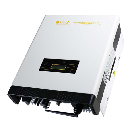
Page 15: Product Appearance
4.2 Product Appearance • Front Object Description Removable front shield LED light (3 pcs) Function keys for displays and choice of language(4 pcs) Monitoring LCD with backlighting • Bottom Object Description DC switch Plug connectors for DC input Terminal for grid connection (AC output) Communication interface(RS485/GPRS/WiFi/USB) -
Page 16: Product Identification
4.3 Product Identification You can identify the inverter by the side name plate. Information such as type of the inverter, inverter specifications are specified on the side name plate. The name plate is on the middle part of the right side of the inverter housing. And the following figure is the side name plate example as onOmniksol-6k-TL2-TH. -
Page 17: Installation
Installation 5.1 Safety DANGER DANGER to life due to potential fire or electricity shock. DO NOT installs the inverter near any inflammable or explosive items. This inverter will be directly connected with HIGH VOLTAGE power generation device; the installation must be performed by qualified personnel only in compliance with national and local standards and regulations. -
Page 18: Mounting Instructions
5.2 Mounting Instructions • Omnik inverter is designed for indoors and outdoors installation • Please mount the inverter in the direction as illustrated above • Install the inverter in the vertical direction is recommended, with a max.15 degrees backwards. • For the convenience of checking the LCD display and possible maintenance activities, please install the inverter at eye level. -
Page 19: Safety Clearance
5.3 Safety Clearance Observe the following minimum clearances to walls, other devices or objects to guarantee sufficient heat dissipation and enough space for pulling the electronic solar switch handle. 10 cm 10 cm Direction Minimum clearance Above 30 cm Below 40 cm Sides 10 cm... -
Page 20: Mounting Procedure
Mounting Procedure 1. Mark 4 positions of the drill holes on the wall according to the wall mounting bracket in the carton box. - Page 21 2. According to the marks, drill 4 holes in the wall. Then place four expansion tubes in the holes using a rubber hammer. Next make 4 screws through the mounting holes in the bracket, and then tighten the screws into the expansion tubes. So far, the wall mounting bracket is fixed already.
-
Page 22: Safety Lock
5.5 Safety lock After the inverter is hanging up on the bracket, lock up the device and the bracket together at the Lower Left Corner of the inverter (as the picture showed below). Padlock Recommended padlock dimension: A φ A.Shackle Diameter 5~7 mm B.Vertical Clearance 8~15 mm... -
Page 23: Electrical Connection
Electrical Connection 6.1 Safety DANGER DANGER to life due to potential fire or electricity shock. With the inverter powered, comply with all prevailing national regulations on accidents prevention. This inverter will be directly connected with HIGH VOLTAGE power generation device; the installation must be performed by qualified personnel only in compliance with national and local standards and regulations. - Page 24 Model Rated current 2.5 mm 4 mm Omniksol-4k-TL2-TH 5.8A Omniksol-5k-TL2-TH 7.2A Omniksol-6k-TL2-TH 8.7A 1) Remove length y of N,L,1,2 conductor 35mm(1.38’’)/PE conductor 40mm(1.57’’) sheath of AC cable terminal, length x about 14mm(0.55’’) of the inner wrapper, then dress the conductor terminals with ferrules or tin soldering.
- Page 25 3) Insert the stripped N, L and PE conductor terminal to the appointed holes, use a cross screwdriver to tighten it with tightening torque 1Nm. Insert the connector to clamp ring with two click sound and then tighten the hex nut with tightening torque 4Nm.
-
Page 26: Dc Side Connection
NEVER connect or disconnect the connectors under load. DANGER NEVER connect the ground lead of PV module to the inverter. For Omniksol-4k-TL2-TH, Omniksol-5k-TL2-TH and Omniksol-6k-TL2-TH, there are two MPP Trackers, and the DC characteristics of them are illustrated as the following table. Max. Max. - Page 27 The use of PVC cables is not recommended. Unplugging under load: PV plug connections must not be unplugged while under load. They can be placed in a no load state by switching off the DC/AC converter or breaking the DC circuit interrupter. Plugging and unplugging while under voltage is permitted.
- Page 28 (ill. 2) Crimping pliers PV-CZM... incl. locator and built-in crimping insert. Crimping range: 2,5 / 4 / 6 mm² (12 / 10 AWG) Type: PV-CZM-19100 Order No. 32.6020-19100 (ill. 3) Open-end spanner PV-MS, 1 Set = 2 pieces Order No.: 32.6024 (ill.
- Page 29 (ill. 11) Open the clamp (K) and hold. Place the contact in the appropriate cross section range. Turn the crimp lugs upwards. Release the clamp (K). The contact is fixed. (ill. 12) Press the pliers gently together until the crimp lugs are properly located within the crimping die.
- Page 30 (ill. 17) Screw up the cable gland hand-tight with the tools PV-MS or tighten the cable gland with the tools PV-WZ-AD/GWD and PV-SSE-AD4. In both cases: The tightening torque must be appropriate for the solar cables used. Typical values are between 2,5 Nm and 3 Nm.
-
Page 31: Display And Operation
Display and Operation 7.1 LCD Panel Object Description LED light(Yellow) – COM LED light(Green) – RUN LED light(Red) – FAULT UP key DOWN key ESC key ENTER key The LCD panel is integrated in the front lid of the inverter, so it is easy for user to check and set the data. -
Page 32: Commissioning
7.2 Commissioning NOTICE The power supply of display module is AC grid, so the screen will not be available until AC is connected. A minimum available voltage of 220Vdc and a DC power of >30Wdc is required before the inverter starts feeding power to the grid. AC side: Turn on the AC circuit break and the display module will works. - Page 33 The system will have the following status: 1. Waiting status: Display as Waiting XXX, XXX refers to the countdown time, will display 1~3 numbers. 2. Flash status: Display as Flash 3. Fault status: Display as Fault XX, XX refers to error code, will display 1~2 numbers. Power and EToday in this interface will change along with the change of number after system operation.
- Page 34 This interface displays the voltage and frequency of grid and the current which inverter outputs to the grid. System operation interface 4: This interface displays the date and time. System operation interface 5: This interface displays the temperature. 7.3.2 Interface introduction Info Interface: You can choose “Info”...
- Page 35 SN and model : WiFi info: Error record display interface: You can choose “Error” by UP and DOWN key in system operation interface 1 While “Error” flickers, confirm to enter the Error record mode. Interface number of the Error record mode is unfixed; it ranges from 0 to 9 interfaces.
- Page 36 Set mode: You can choose “Set” by UP and DOWN key in system operation interface 1 While “Set” flickers, confirm to enter the Set mode. The Set mode is operated with 2 levels of menu. There are 13 items in the sub-menu, Time, Language, Auto Test , Auto Test-F, Password , Safty , Protection , MPPT Scan , Freq Limit , Volt Limit , DC Coef , AC Coef and Reset WiFi.
- Page 37 While “Language” flickers, confirm to enter the language option list. Choose the target language, the corresponding language flickers. English, Dutch and Deutsch are available for displaying. Click ENTER to save data and back to prior menu. Changing Password: In the Set mode, choose “Password” by UP and DOWN key as shown in the picture. While “Password”...
- Page 38 Back to two-level menu mode after saving the password Setting Time: In the Set mode, choose “Time” by UP and DOWN key as shown in the picture. While “Time” flickers, confirm to enter the inverter time setting mode. Use ENTER key to choose the one you want modify and UP/DOWN key to change the value.
- Page 39 The selected safety information flickers. The selectable safety information as following: Italy VDE-4105 VDE-0126 Spain GREMAIN Portugal Belgium Italy _ S EnglG83 EnglG59 Austral China GerBDEW Dan mark GreIsla Czech Slovak Holland Sweden Bulgaria France Brazil EngG592 Holl16A SAfrica These safety information will be arranged in 4 lines, i.e. there will be 4 safety information displayed in the same interface.
-
Page 40: State Information
7.4 State Information State Display State information Waiting Initialization & waiting Wait Reconnects Reconnect Checking’s Checking Normal Normal Normal state Current Fault GFCI failure oversized leakage current Master Grid Freq Fault Grid frequency failure Master Grid Freq Fault Grid voltage failure PV Voltage Fault Input voltage too high Over Temp Fault... -
Page 41: Communication Setting
Communication Setting GPRS Card GPRS card is an optional device. If your inverter had installed the GPRS card, please go to 8.3. Register on monitoring website. After unpacking the box, please check the parts according to the below list. Contact the manufacturer immediately when you find any damage, missing or wrong model. -
Page 42: Installation Of Communication Card
Fig. GPRS card with card slot Name 14 pin connector SIM card slot I-PEX Interface The serial number is shown as below. Fig. Serial Number Installation of communication card Warning: Before installing the GPRS card to inverter, you must turn off both the AC side and DC side of inverter to make sure personal safety. - Page 43 Fig. Dismantle the communication box Unscrew the four screws on the interface panel with the screwdriver as shown in Picture above and keep the screws aside. Fig. Communication box and connector The standard connector has two holes. Use the single-hole rubber washer to take place of the double-hole rubber washer.
- Page 44 Insert the GPRS antenna through the gland and screw the hex nut with a torque of 2.0 N.m. Fig. Insert the GPRS antenna Connect the data line into the I-PEX interface. Fig. Connect the GPRS antenna While using the second kind of GPRS card, just insert the SIM card into the card slot. Then insert the GPRS card into the inverter.
-
Page 45: Register On Monitoring Website
Install the communication box back to the inverter. While the installation is completed, Antenna can be turned in 360 degrees. Fig. Complete the installation Register on monitoring website The PV monitoring system of Omnik is supported by: IE8, Firefox, Chrome, and Safari. Login the website http://www.omnikportal.com, click register to enter the user registration page, follows the requirements for registration;... - Page 46 Fig. Choose the account type Remarks: please read the < Omnik service agreement > carefully, the enclosure is the cost list for all the countries; please choose your operators End User means the final user “*” you must fill it...
- Page 47 Fig. Fill in the power station information...
- Page 48 Fig. Fill in the power station information After the register, you may enter next chapter 8.4 Login Monitoring System.
-
Page 49: Login Monitoring System
Login monitoring System After the successful register and account activation, open the login interface as below. Input the correct email and code. Enter the PV monitoring system. Then you can monitor and manage the power station. Input the correct email and code Fig. - Page 50 Fig. List of power station Enter the configure Enter the Back to user Not yet open “company account” sharing case interface interface Reset Add one case under your account Fig. Navigation Bar...
- Page 51 Change case Energy saving Case info Real-time power and generated energy switchover Print current figure Power station info Fig. Main interface of Power Station...
- Page 52 Internal Latest data collecting time Fig . Real Time Interface Parameter options Choose the aim inverter Fig. History Interface...
- Page 53 Fig. Alert Interface Fig. System Setting Interface...
-
Page 54: Wifi Card
Fig. Add serial number WiFi card WiFi card is an optional device. If your inverter had installed the WiFi card, please go to 8.6. Network Settings. If your inverter had not installed the WiFi card, please go to 8.2. Installation of communication card first, then go to 8.6. Network Settings. After unpacking the box, please check the parts according to the below list. -
Page 55: Netwoek Settings
WiFi card is shown as below: Name 14 pin connector Reset Button I-PEX Interface Fig. WiFi card Fig. Serial Number Netwoek Settings 1) Prepare a computer or device, e.g. tablet PC and smart phone that enables WiFi 2) Obtain an IP address automatically Open Wireless Network Connection Properties, double click Internet Protocol ... - Page 56 3) Open wireless network connection and click View Wireless Networks Select wireless network of the data logging module, no passwords required as default. The network name consists of AP and the serial number of the product. Then click Connect.
- Page 57 Connection successful Notice: If AP_ (serial number of product) is not available in the wireless network list, there may be problems in the connection or setting of data logging module. Please check if the WiFi had installed ok, and inverter has been powered on. Before troubleshooting, please inquire with your inverter installer whether you are allowed to remove the cover of the inverter to trouble shoot the module.
- Page 58 admin admin (b) In the configuration interface of WiFi module, you can view general information of the module. Follow the setup wizard to start quick setting. Click Wizard to start...
- Page 59 Click Start to continue Click Refresh to search available wireless networks...
- Page 60 Next Select the wireless network you need to connect, then click Notice: ① If the signal strength (RSSI) of the selected network is <10%, which means unstable connection, please adjust the antenna of the router, or use a repeater to enhance the signal. ②...
- Page 61 Enter the password for the selected network, then click Next Select Enable to obtain an IP address automatically, then click Next Notice: ① Turn off the firewall of the router ② Make sure the DHCP function of the router is enable...
- Page 62 If setting is complete, the above page will display. Click OK to restart. If setting is complete, the above page will display. After your WiFi card set ok and get IP address from your router for example: 192.168.16.8, (You may see the IP address from inverter) Input: http://192.168.16.8/ will display the following page:...
- Page 63 You may also add your domain name of WiFi card to easy access according below picture , after you set ok, input http://wifi, you may also access the related page.
-
Page 64: Ethernet Card
Now we finish the network setting, please go to 8.3. Register on monitoring website. Ethernet Card Ethernet card is an optional device. If your inverter had installed the Ethernet card, please go to 8.3. Register on monitoring website. If your inverter had not installed the WiFi card, please go to 8.8. -
Page 65: Installation Of Ethernet Card
Name RJ45 connector 14 pin connector Reset button The serial number is shown as below. Installation of Ethernet card Warning: Before installing the Ethernet card to inverter, you must turn off both the AC side and DC side of inverter to make sure personal safety. Unscrew the four screws on the interface panel with the screwdriver as shown in Picture above and keep the screws aside. - Page 66 Wear the Ethernet cable into the waterproof terminals, and waterproof terminals and the cover plate is installed. Insert the Ethernet card into the inverter. Connect the Ethernet cable to the Ethernet card.
-
Page 67: Rs485 Card
Strengthen waterproof case closely back to the inverter. Then connect the other side of the Ethernet cable to the router LAN port RS485 card CON 3 14 pin connector CON 2 CON 1 SD Card Slot Fig. RS485 card CON 3 CON 2 CON 1... - Page 68 There are 3 connectors in the new RS485 card. The definition of the connectors is shown in the table. Connector Name Description Connection RS485+ Signal CON1 RS485- Signal Wi-Fi/GPRS Kit RS485 GND RS485+ Signal CON2 RS485- Signal DTSU 666 RS485 GND Relay Operation CON3 Alarm...
- Page 69 The definition of the connector is shown in the table. RJ45 CON 2 CON 2 is only used to communicate with DTSU 666. It can be applied for solar projects of self-consumption without power export to the grid. It can ensure that the power generated by solar system will not export to grid at anytime.
- Page 70 The definition of the connector is shown in the table. ammeter Live-A(grid side) Live-A(inverter side) Live-B(grid side) Live-B(inverter side) Live-C(grid side) Live-C(inverter side) RS485-A RS485-B The second type of meter is used with CT as shown below.
- Page 71 The definition of the connector is shown in the table. ammeter Live-A Live-B Live-C CT- Live- CT- Live-A CT- Live-B CT- Live- CT- Live-C CT- Live-C RS485-A RS485-B...
-
Page 72: Recycling And Disposal
Please refer to the corresponding instructions for installation and use of the meter (DTSU 666). CON 3 CON 3 is used to control the alarm LED. It is a pair of Normally open contacts. The load capacity of the Relay is 230 V/0.5 A. Recycling and Disposal To comply with European Directive 2012/19/EU on waste Electrical and Electronic Equipment and its implementation as national law, electrical equipment that has... -
Page 73: Troubleshooting
10. Troubleshooting Fault Fault Info On Possible Reasons Solutions Display 1.Restart to check GFCI Device Fault Inverter GFCI Detector Issue 2.Re-Flash software 3.Replace part or inverter Restart to check after local grid is No Grid or Local Grid Island Fault stable Frequency Isn't Stable Close the protection from the inverter... - Page 74 1.Correct The Installation (Remove DC Voltage Is Too High Due Panels) PV Volt High To Wrong Installation 2.Re-Flash Software 3.Replace Part Or Inverter Grid Voltage Detection Within Change the grid voltage protection Grid Volt Fault A Period Is Anomalous range 1.Remove this Fault Impedance To Ground 2.Change it to another standard with...
-
Page 75: Abbreviation
11. Abbreviation Liquid Crystal Display Light Emitting Diode MPPT Maximum Power Point Tracking Photovoltaic Voltage at the DC side Voltage at the AC side Vmpp Voltage at the Maximum Power Point Impp Amperage at Maximum Power Point Alternating Current ( Form of electricity supplied by Utility Company ) Direct Current ( Form of electricity generated by PV modules ) -
Page 76: Contact
12. Contact Omnik New Energy Co.,Ltd.(Headquarters) Address: Third Floor,Building 3,No.63 Weixin Road,SIP,Suzhou,China Tel: +86-512-6956-8216 Fax: +86-512-6295-6682 E-mail: sales @omnik-solar.com sevice@omnik-solar.com Website: www.omniksolar.com Omnik German branch Address: Omnik Gmbh Forsthausstr.8A 65479 Raunheim Tel: +49(0) 1799762654 Mobile: +49(176) 30743149 E-mail: jingjing.zhang@omnik-solar.com Omnik UK Service Partner... - Page 77 GUARANTEE CARD Agency retention ------------------------------------------------------------------------------------------------------------ 的 User information 得 Product Model Product ID Purchase Date Customer Name 的 Historical Warranty 的 Warranty date Troubleshooting Finished date Customer Signature Client retention...
- Page 78 的 User Information 得 Product Model Product ID Purchase Date Customer Name 的 Historical Warranty 的 Warranty date Troubleshooting Finished date Customer Signature -------------------------------------------------------------------------------------------------------------------------------------------------------------------------------- 的 的 Warranty Terms 1. Please fill in this card carefully and read the following warranty terms carefully to ensure that the product is effectively guaranteed.
Need help?
Do you have a question about the Omniksol-5k-TL2-TH and is the answer not in the manual?
Questions and answers