Hide thumbs Also See for RAI-25RPE:

Advertisement

Quick Links

INSTALLATION AND OPERATION MANUAL
MANUAL DE INSTALACIÓN Y FUNCIONAMIENTO
INSTALLATIONS- UND BETRIEBSHANDBUCH
MANUEL D'INSTALLATION ET DE FONCTIONNEMENT
MANUALE D'INSTALLAZIONE E D'USO
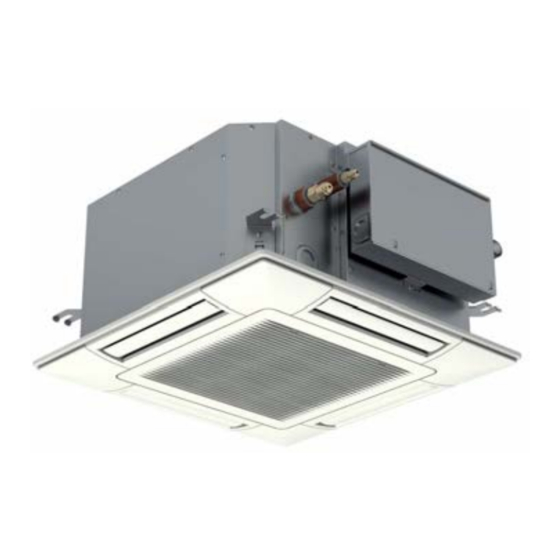
INDOOR UNITS SYSTEM
RAI-25RPE, RAI-35RPE, RAI-50RPE, RAI-60RPE
MANUAL DE INSTALAÇÃO E DE FUNCIONAMENTO
INSTALLATIONS- OG BETJENINGSVEJLEDNING
INSTALLATIE- EN BEDIENINGSHANDLEIDING
INSTALLATION- OCH DRIFTHANDBOK
4-way cassette - R32

Advertisement

Table of Contents
loading

Summary of Contents for Hitachi RAI-25RPE

  • Page 1 INSTALLATION AND OPERATION MANUAL INSTALLATIONS- OG BETJENINGSVEJLEDNING MANUAL DE INSTALACIÓN Y FUNCIONAMIENTO INSTALLATIONS- UND BETRIEBSHANDBUCH INSTALLATIE- EN BEDIENINGSHANDLEIDING MANUEL D’INSTALLATION ET DE FONCTIONNEMENT INSTALLATION- OCH DRIFTHANDBOK MANUALE D’INSTALLAZIONE E D’USO INDOOR UNITS SYSTEM 4-way cassette - R32 RAI-25RPE, RAI-35RPE, RAI-50RPE, RAI-60RPE...
  • Page 3 English Español Deutsch Français Italiano Português Dansk Nederlands Svenska...
  • Page 4 C A U T I O N This product shall not be mixed with general house waste at the end of its life and it shall be retired according to the appropriated local or national regulations in a environmentally correct way. Due to the refrigerant, oil and other components contained in Air Conditioner, its dismantling must be done by a profes- sional installer according to the applicable regulations.
  • Page 5 DANGER PELIGRO GEFAHR DANGER PERICOLO PERIGO FARE GEVAAR FARA KINAYNO CAUTION PRECAUCIÓN VORSICHT PRECAUTION ATTENZIONE CUIDADO FORSIGTIG LET OP VARNING NOTE NOTA HINWEIS REMARQUE NOTA NOTA BEMÆRK OPMERKING...
  • Page 6 WA R N U N G Dieses auf dem Gerät angezeigte Symbol zeigt an, dass das Gerät WA R N I N G ist mit dem R32 geruchlosen brennbaren Kältemittel mit niedriger Brenngeschwindigkeit gefüllt (Klasse A2L gemäß ISO 817). Bei ei- BURST HAZARD nem Kältemittelaustritt besteht die Gefahr der Entzündung, wenn das Do not allow air or any gas mixture containing oxygen into refrigerant...
  • Page 7 AV V E R T E N Z A WA A R S C H U W I N G Dit symbool op het apparaat geeft aan dat het apparaat is gevuld met R32, een geurloos ontvlambaar koelmiddel met een lage brandsnel- heid (klasse A2L volgens ISO 817).
  • Page 8 This product contains biocidal substances according to EU Reg. 528/2012 Dieses Produkt enthält Biozide nach EU Verordnung 528/2012 Conformément à la Reg UE 528/2012, ce produit contient des substances biocides Questo prodotto contiene sostanze biocidi ai sensi del Reg. UE 528/2012 Este produto contém substâncias biocidas de acordo com o Regulamento (UE) N.º...
  • Page 9 INHALTSVERZEICHNIS ÍNDICE INDHOLDSFORTEGNELSE INDEX INHOUDSOPGAVE INDICE...
  • Page 10 INNEHÅLLSFÖRTECKNING English Original version...
  • Page 11: General Information

    GENERAL INFORMATION 1 GENERAL INFORMATION 1.1 GENERAL NOTES HITACHI makes every effort to offer correct, up-to-date or transmitted in any shape or form without the permission of documentation. Despite this, printing errors cannot be controlled Johnson Controls-Hitachi Air Conditioning Spain, S.A.U.
  • Page 12: Important Notice

    For use in other applications, of the collection tray and into the electrical box. Water leaks or please contact your HITACHI dealer or service contractor. electrical faults may eventually be caused. Do not install the unit in a place where the current of expelled...
  • Page 13 IMPORTANT NOTICE Low temperature solder alloys, such as lead/tin alloys, are not acceptable for pipe connections. or inlet. As the fan is rotating at high speed, it will cause Brazed, welded or mechanical connection shall be made injury. Before cleaning, be sure to stop the operation and turn the breaker OFF.
  • Page 14 IMPORTANT NOTICE or explosion, including cigarette smoking, must be kept damage. The check shall also take into account the effect of ageing or continual vibration from sources such as may be released to the surrounding space. The area around compressors of fans. the equipment shall be checked before beginning the work refrigerants, but the sensitivity may not be adequate, or may Smoking”...
  • Page 15: Before Operation

    BEFORE OPERATION or lines shall be as short as possible to minimise the with OFN. The system shall be leak tested on completion amount of refrigerant contained in them. of charging but prior to commissioning. A follow up leak test shall be carried out prior to leaving the site.
  • Page 16: Maintenance

    MAINTENANCE 4.2 EFFICIENT USE OF COOLING AND HEATING COOLING HEATING direction. Pay attention to dew drop which may occur due to direction. the long cooling operation with low louvre angle. 60° 60° 35° 35° Louver Louver angle angle Air outlet angle (above center) Air outlet angle (above center) N O T E 5 MAINTENANCE...
  • Page 17: Daily Maintenance

    MAINTENANCE 5.1 DAILY MAINTENANCE 5.1.1 Cleaning Air Filter 5.1.2 Removing, attaching and cleaning air inlet grille 1 Open the air inlet grille. N O T E While sliding the knobs on both side of the air inlet grille in the arrow direction, open the air inlet grille. The air inlet grille can be removed and cleaned.
  • Page 18: Name Of Parts

    NAME OF PARTS 5.2 MAINTENANCE AT BEGINNING AND END OF USE At beginning of use At end of use Remove obstacles around the air inlet grilles and the air outlet of the indoor unit and outdoor unit. 6 NAME OF PARTS Nº...
  • Page 19: Before Installation

    BEFORE INSTALLATION 7 BEFORE INSTALLATION 7.1 TRANSPORTATION AND HANDLING 7.1.2 Handling of indoor unit C A U T I O N D A N G E R 7.1.1 Transportation of indoor unit Transport the product as close to the installation location as possible before unpacking.
  • Page 20: Factory-Supplied Accessories

    INDOOR UNIT INSTALLATION 8.1 FACTORY-SUPPLIED ACCESSORIES Check to ensure that the following accessories are packed with the indoor unit. The hose band, screws, washers and plastic bands are put in the pipe insulation. Accessory Qty. Purpose Checking scale For adjusting space of false ceiling opening and position of (cut and take out it from the carton board) the unit Washer with insulation material (M10)
  • Page 21: Initial Check

    INDOOR UNIT INSTALLATION 8.2 INITIAL CHECK Suspension bolt for Install the indoor unit with a proper clearance around it indoor unit paying careful attention of installation direction for the piping, wiring and maintenance working space, as shown below. The electrical box is located to the side surface of the unit body.
  • Page 22: Opening Of False Ceiling And Location Of Suspension Bolts

    INDOOR UNIT INSTALLATION 8.3 INSTALLATION Opening of false ceiling and location of suspension bolts Install the indoor unit to the tie beam (for single-storied building) the indoor unit paying attention to the space for the piping, wiring and maintenance. Interval between beams Squared timber Then cut out the false ceiling for the indoor unit installation <...
  • Page 23 INDOOR UNIT INSTALLATION b. The positional relation between the indoor unit and the 4 Mounting indoor unit a. Lift up the indoor unit by a hoist, and do not apply any (mm) force to the drain pan (the air outlet portions and the 4-positions of suspension bolts (M10 or W3/8) drain pan portion).
  • Page 24: Installation Of Remote Control Switch

    INDOOR UNIT INSTALLATION b. For false ceiling without opening 7 The upper surface of the unit is protected by corrugated cardboard to prevent the unit from being damaged by If there is no opening in the existing false ceiling, provide spatter, etc.
  • Page 25: Refrigerant Piping

    REFRIGERANT PIPING 9 REFRIGERANT PIPING Before refrigerant piping work, drain piping work and insulation are required. Refer to the for details. D A N G E R 9.1 PIPING POSITION (Drain pipe) N O T E (Liquid pipe) (Gas pipe) Drain pipe connection Refrigerant liquid pipe...
  • Page 26 REFRIGERANT PIPING 9.3 PIPING CONNECTION SIZE Required tightening torque Flare pipe dimensions Pipe Size Tightening Torque 14 - 18 (N-m) mm (in.) 34 - 42 (N-m) Diameter ( Ø12.7 mm (1/2) 49 - 61 (N-m) -0.4 68 - 82 (N-m) 13.2 0.4 ~ 0.8R N O T E...
  • Page 27: Drain Piping

    DRAIN PIPING If coating the optional air panel with a forming agent insulations to prevent dew condensation. Then insulate each refrigerant pipe as well. forming agent does not contact it. Otherwise, it could cause a breakage of the panel, resulting in the panel falling. If the Fasten securely cord clamps and forming agent contacts the air panel, completely wipe it off.
  • Page 28 DRAIN PIPING 6 Insert the drain hose completely. If it is not inserted properly, or if it is twisted, water leakage may occur. On-site drain piping work CORRECT Connect the factory-supplied drain hose to the drain pipe connection using the polyvinyl chloride adhesive. Drain pipe connection When cleaning the connection surface, applying the...
  • Page 29 DRAIN PIPING Drainage and water leakage check After performing drain piping work and the electrical wiring and up mechanism. smoothly according to the following procedure. a. Turn OFF the power supply. operation. to "TEST" position. a. Turn ON the power supply. c.
  • Page 30: Electrical Wiring

    ELECTRICAL WIRING 11 ELECTRICAL WIRING 11.1 GENERAL INFORMATION D A N G E R C A U T I O N General check (main power switches, circuit breakers, wires, conduit connectors and wire terminals) have been properly selected. Make sure that the components comply with National Electrical Code (NEC).
  • Page 31: Position Of Electrical Wiring Connection

    ELECTRICAL WIRING 11.3 POSITION OF ELECTRICAL WIRING CONNECTION C A U T I O N Connect the cable for the optional remote control switch or the optional extension cable to the terminals inside the electrical box through the connecting hole in the cabinet. Connect the power supply and the earth wires to the terminals in the electrical box.
  • Page 32: Electrical Wiring Capacity

    ELECTRICAL WIRING 11.4 ELECTRICAL WIRING CAPACITY 11.4.1 Field minimum wire sizes for power N O T E source Use an ELB (Earth Leakage Breaker). If not used, it will Do not operate the system until all the check points have Check to ensure that the electrical resistance is more than 1 megohm, by measuring the resistance between ground and the terminal of the electrical parts.
  • Page 33: Applicable Model

    12 INSTALLATION OF OPTIONAL AIR PANEL: P-AP56NAMS 12.1 APPLICABLE MODEL Air panel Indoor unit model 12.2 TRANSPORTATION AND HANDLING 1 Transport the air panel without unpacking as close to the In addition, if the air panel is placed with the surface installation location.
  • Page 34 The operation is continued even if there is no person in a room. Pay attention that the detecting function is decreased if the lens for sensor smudges. Object such as a curtain or a leafy plant is swaying in the wind in the detecting area.
  • Page 35 4 Remove the corner pocket covers. The corner pocket covers can be removed pulling part Do not use the impact driver or big torque tools using panel mounting work. Refrigerant pipe Indoor unit Electrical box Fixing plate (Indoor unit) Indication Mounting sheet 5 Check to ensure that the distance between the indoor unit "PIPE SIDE"...
  • Page 36 10 Attachment of corner pocket cover N O T E Attach the corner pocket covers (4 portions) after the air panel is mounted completely. Air leakage a. Catch the band at the rear side of the corner pocket cover onto the projection at the air panel as shown in the Smudge Projection Dewing...
  • Page 37 12.5 ELECTRICAL WIRING C A U T I O N CN10 Cable for motion sensor Cable for auto swing motor N O T E After completing the wiring connection of the air panel, attach This motion sensor can be installed to any four corners of the air the air inlet grille.
  • Page 38: Optional Part

    OPTIONAL PART 12.6 TEST RUN 1 After completing the installation of the air panel, the test run Do not move the louvre by hand. If moved, the auto-swing should be performed. mechanism will be damaged. 2 Perform the checking work for the louvre during the test run. 12.7 ADJUSTING LOUVRES Louvre N O T E...
  • Page 39 Johnson Controls-Hitachi Air Conditioning Spain, S.A.U. Ronda Shimizu, 1 - Políg. Ind. Can Torrella 08233 Vacarisses (Barcelona) Spain © Copyright 2019 Johnson Controls-Hitachi Air Conditioning Spain, S.A.U. – All rights reserved. Printed in Spain...

This manual is also suitable for:

Rai-35rpeRai-50rpeRai-60rpe

Table of Contents