Hitachi RAI-25NH5 Service Manual
Room air conditioner
Hide thumbs
Also See for RAI-25NH5:
- Instruction manual (23 pages) ,
- Service manual (371 pages) ,
- Information booklet & user manual (68 pages)
Table of Contents
Advertisement
SERVICE MANUAL
TECHNICAL INFORMATION
FOR SERVICE PERSONNEL ONLY
RAI-ECPM
RAI-25NH5
RAI-35NH5
NOTE:
This manual describes only points that differ from
RAK-18NH5, 25NH5, 35NH5 (PM NO. 0269E) and
RAM-40QH5 (PM NO. 0270E) for items not described
in this manual.
SPECIFICATIONS
TYPE
MODEL
POWER SOURCE
TOTAL INPUT
TOTAL AMPERES
COOLING
CAPACITY
TOTAL INPUT
TOTAL AMPERES
HEATING
CAPACITY
DIMENSIONS
(mm)
NET WEIGHT
SPECIFICATIONS AND PARTS ARE SUBJECT TO CHANGE FOR IMPROVEMENT
ROOM AIR CONDITIONER
SEPTEMBER 2005
RAI-25NH5
1 PHASE, 50 Hz, 220-240V
(W)
(A)
(kW)
(B.T.U./h)
(W)
(A)
(kW)
(B.T.U./h)
W
H
D
(kg)
INDOOR UNIT
Refrigeration & Air-Conditioning Division
PM
RAI-25NH5
RAI-35NH5
REFER TO THE FOUNDATION MANUAL
SPECIFICATIONS ------------------------------------------------------------------- 4
HOW TO USE ------------------------------------------------------------------------ 6
CONSTRUCTION AND DIMENSIONAL DIAGRAM --------------------- 27
MAIN PARTS COMPONENT --------------------------------------------------- 28
WIRING DIAGRAM ---------------------------------------------------------------- 29
CIRCUIT DIAGRAM --------------------------------------------------------------- 31
PRINTED WIRING BOARD LOCATION DIAGRAM --------------------- 35
BLOCK DIAGRAM ----------------------------------------------------------------- 37
BASIC MODE ----------------------------------------------------------------------- 39
REFRIGERATING CYCLE DIAGRAM --------------------------------------- 53
AUTO SWING FUNCTION ------------------------------------------------------ 55
DESCRIPTION OF MAIN CIRCUIT OPERATION ----------------------- 56
TROUBLE SHOOTING ----------------------------------------------------------- 64
PARTS LIST AND DIAGRAM -------------------------------------------------- 69
DC INVERTER (CEILING CASSETTE TYPE)
INDOOR UNIT
REFER TO THE SPECIFICATIONS PAGE (5)
580
285
580
20
NO. 0271E
CONTENTS
RAI-35NH5
1 PHASE, 50 Hz, 220-240V
580
285
580
20
Advertisement
Table of Contents

Related Manuals for Hitachi RAI-25NH5


Summary of Contents for Hitachi RAI-25NH5
-
Page 1: Table Of Contents
NO. 0271E RAI-25NH5 RAI-35NH5 SERVICE MANUAL REFER TO THE FOUNDATION MANUAL TECHNICAL INFORMATION FOR SERVICE PERSONNEL ONLY CONTENTS SPECIFICATIONS ------------------------------------------------------------------- 4 HOW TO USE ------------------------------------------------------------------------ 6 CONSTRUCTION AND DIMENSIONAL DIAGRAM --------------------- 27 MAIN PARTS COMPONENT --------------------------------------------------- 28 WIRING DIAGRAM ---------------------------------------------------------------- 29... - Page 2 SAFETY DURING REPAIR WORK 1. In order to disassemble and repair the unit in question, be sure to disconnect the power cord plug from the power outlet before starting the work. 2. If it is necessary to replace any parts, they should be replaced with respective genuine parts for the unit, and the replacement must be effected in correct manner according to the instructions in the Service Manual of the unit.
- Page 3 WORKING STANDARDS FOR PREVENTING BREAKAGE OF SEMICONDUCTORS 1. Scope The standards provide for items to be generally observed in carrying and handling semiconductors in relative manufacturers during maintenance and handling thereof. (They apply the same to handling of abnormal goods such as rejected goods being returned).
- Page 4 (6) Use a three wire type soldering iron including a grounding wire. Metal plate (of aluminium, stainless steel, etc.) Working table Resistor of 1 M (1/2W) Staple Earth wire Bare copper wire (for body earth) Fig. 3. Grounding of the working table Soldering iron Grounding wire...
- Page 5 CAUTION In quiet operation or stopping the running, slight flowing noise of refrigerant in the refrigerating cycle is heard occasionally, but this noise is not abnormal for the operation. When it thunders near by, it is recommend to stop the operation and to disconnect the power cord plug from the power outlet for safety.
-
Page 6: Specifications
SPECIFICATIONS RAI-25NH5 MODEL RAI-35NH5 FAN MOTOR FAN MOTOR CAPACITOR FAN MOTOR PROTECTOR COMPRESSOR – COMPRESSOR MOTOR CAPACITOR OVERLOAD PROTECTOR OVERHEAT PROTECTOR FUSE (for MICROPROCESSOR) POWER RELAY POWER SWITCH TEMPORARY SWITCH SERVICE SWITCH TRANSFORMER VARISTOR NOISE SUPPRESSOR THERMOSTAT YES(IC) REMOTE CONTROL SWITCH (LIQUID CRYSTAL) - Page 7 SPECIFICATIONS FOR INDOOR UNITS COMBINATIONS CEILING CASSETTE TYPE DC INVERTER QUADRUPLE TYPE SYSTEM MULTI COOLING AND HEATING INDOOR UNIT RAI-25NH5 RAI-35NH5 MODEL RAM-40QH5 OUTDOOR UNIT PHASE/VOLTAGE/FREQUENCY 1ø, 220V-240V, 50Hz CIRCUIT AMPERES TO CONNECT (A) 2.50 (1.00 ~ 3.00) 3.50 (1.00 ~ 4.00) CAPACITY (kW) (B.T.U./h)
-
Page 8: Safety Precaution
SAFETY PRECAUTION Please read the “Safety Precaution” carefully before operating the unit to ensure correct usage of the unit. Pay special attention to signs of “ Warning” and “ Caution”. The “Warning” section contains matters which, if not observed strictly, may cause death or serious injury. The “Caution” section contains matters which may result in serious consequences if not observed properly. - Page 9 PRECAUTIONS DURING OPERATION The product shall be operated under the manufacturer specification and not for any other intended use. Do not attempt to operate the unit with wet hands, this could cause fatal accident. When operating the unit with burning equipments, regularly ventilate the room to avoid oxygen insufficiency.
-
Page 10: Names And Functions Of Each Part
MODEL WIDTH (mm) HEIGHT (mm) DEPTH (mm) RAI-25NH5 / RAI-35NH5 MULTI-AIR CONDITIONER With this multi-air conditioner, several indoor units can be connected to one outdoor unit to be driven. You can operate the required number of indoor units. Combination of Operations:... -
Page 11: Indoor Unit Indicators
OPERATION INDICATOR TEMPORARY SWITCH TEMPORARY SWITCH Use this switch to start and stop when the remote controller does not work. Temporary Switch [Use non-conductor stick (example toothpick)] By pressing the temporary switch, the operation is done in previously set Press operation mode. -
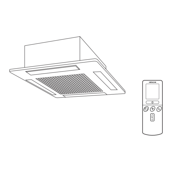
Page 12: Names And Functions Of Remote Control Unit
NAMES AND FUNCTIONS OF REMOTE CONTROL UNIT REMOTE CONTROLLER Operate by pointing towards the signal receptor on the indoor unit. The range of control is about 7 meters. Signal receivable angle range is approximately 70°. However, if there is an electronic light sensor device (inverter) in the room, signal may not be received or receivable distance may become shorter. -
Page 13: Automatic Operation
VARIOUS FUNCTIONS I Auto Restart Control If there is a power failure, operation will be automatically restarted when the power is resumed with previous operation mode and airflow direction. (As the operation is not stopped by remote controller.) If you intend not to continue the operation when the power is resumed, switch off the power supply. When you switch on the circuit breaker, the operation will be automatically restarted with previous operation mode and airflow direction. -
Page 14: Heating Operation
HEATING OPERATION Use the device for heating when the outdoor temperature is under 21°C. When it is too warm (over 21°C), the heating function may not work in order to protect the device. In order to keep reliability of the device, please use this device above -15°C of the outdoor temperature. Press the FUNCTION selector so that the display indicates (HEAT). -
Page 15: Dehumidifying Operation
DEHUMIDIFYING OPERATION Use the device for dehumidifying when the room temperature is over 16°C. When it is under 15°C, the dehumidifying function will not work. Press the FUNCTION selector so that the display indicates (DEHUMIDIFY). ˚ The FAN SPEED is set at LOW automatically. The FAN SPEED button does not work. -
Page 16: Cooling Operation
COOLING OPERATION Use the device for cooling when the outdoor temperature is 22-42°C. If in doors humidity is very high (80%), some dew may form on the air outlet grille of the indoor unit. Press the FUNCTION selector so that the display indicates (COOL). -
Page 17: Fan Operation
FAN OPERATION You can use the device simply as an air circulator. Use this function to dry the interior of the indoor unit at the end of summer. Press the FUNCTION selector so that the display indicates (FAN). Press the (FAN SPEED) button. -
Page 18: How To Set The Timer
HOW TO SET THE TIMER Time, Day, Month Set the current month and TIME, DAY, day with the TIMER control After you change the MONTH button. batteries; (current time, day, month) OFF TIMER RESET ON TIMER OFF-Timer Press the (OFF-TIMER) button. - Page 19 Set the current time with the Press the (TIME) button again. Press the TIMER control button. The time indication starts lighting (TIME) button. instead of flashing. The time indication will disappear automatically in 10 second. To check the current time setting, press the (TIME) button twice.
-
Page 20: How To Set The Sleep Timer
HOW TO SET THE SLEEP TIMER Set the current time at first if it is not set before (see the pages for setting the current time). Press the (SLEEP) button, and the display changes as shown below. Mode Indication 1 hour 2 hours 3 hours 7 hours... -
Page 21: Adjusting The Air Deflector
ADJUSTING THE AIR DEFLECTOR Adjustment of the conditioned air in the upward and downward directions. According to “Dehumidifying” or “Cooling” operation, the horizontal air deflector is automatically set to the proper angle suitable for each operation. The deflector can be RESET swung up and down and also set to the desired angle using the “... -
Page 22: How To Exchange The Batteries In The Remote Controller
HOW TO EXCHANGE THE BATTERIES IN THE REMOTE CONTROLLER Remove the cover as shown in the figure and take out the Push and pull to the old batteries. direction of arrow Install the new batteries. The direction of the batteries should match the marks in the case. -
Page 23: Suitable Room Temperature
THE IDEAL WAYS OF OPERATION Suitable Room Temperature Install curtain or blinds Warning It is possible to Freezing temperature reduce heat is bad for health and a entering the waste of electric power. room through windows. Ventilation Effective Usage Of Timer At night, please use the “OFF or ON timer Caution operation mode”, together with your wake up... - Page 24 FOR USER’S INFORMATION The Air Conditioner And The Heat Source In The Room Caution If the amount of heat in the room is above the cooling capability of the air conditioner (for example: more people entering the room, using heating equipments and etc.), the preset room temperature cannot be achieved.
- Page 25 MAINTENANCE CAUTION Cleaning and maintenance must be carried out by qualified service personnel. Before the cleaning, stop operation and disconnect the power supply. Clean the filter at least once every one month. This helps save electricity cost. CLEANING OF AIR FILTER REMOVAL AND ATTACHMENT OF AIR FILTER PROCEDURE PUSH...
-
Page 26: Cleaning Of Front Panel
2. CLEANING OF FRONT PANEL Wipe it with a soft dry cloth. When it is excessively dirty, wipe with soft cloth soaked in lukewarm water or neutral detergent. Then wipe thoroughly with a soft dry cloth. CAUTION Do not splash or direct water to the body of the unit when cleaning it as this may cause short circuit. - Page 27 AFTER SALES SERVICE AND WARRANTY WHEN ASKING FOR SERVICE, CHECK THE FOLLOWING POINTS. CONDITION CHECK THE FOLLOWING POINTS Is the fuse blown out or the circuit breaker tripped? Is the voltage normal? When it does not operate Is the circuit breaker “ON”? Is the air filter blocked with dust? Does sunlight fall directly on the outdoor unit? Is the air flow of the outdoor unit obstructed?
- Page 28 Please note: On switching on the equipment, particularly when the room light is dimmed, a slight brightness fluctuation may occur. This is of no consequence. The conditions of the local Power Supply Companies are to be observed. Note Avoid to use the room air conditioner for cooling operation when the outside temperature is below 21°C (70°F).
-
Page 29: Construction And Dimensional Diagram
CONSTRUCTION AND DIMENSIONAL DIAGRAM MODEL RAI-25NH5, RAI-35NH5 650 (Panel) Unit : mm 600 (Opening on ceiling) 580 (Indoor unit) 400 (Suspension bolt) Wireless remote controller 97 (Drain) Narrow pipe fl6.35 Drain outlet Wide pipe fl12.7 Panel (Optional part RAI-ECPM) Ceiling... -
Page 30: Main Parts Component
MAIN PARTS COMPONENT THERMOSTAT Thermostat Specifications THERMOSTAT MODEL OPERATION MODE COOL HEAT MODEL RAI-25NH5 RAI-35NH5 RAI-25NH5, RAI-35NH5 15.0 (59.0) 13.0 (55.4) 20.0 (68.0) INDICATION 14.7 (58.5) 12.7 (54.9) 20.3 (68.5) TEMPERATURE 23.0 (73.4) 21.0 (69.8) 28.0 (82.4) INDICATION °C (°F) 22.7 (72.9) - Page 31 – 29 –...
-
Page 32: Circuit Diagram
CIRCUIT DIAGRAM Remote Control Key matrix table Output Input Door open Start/Stop Operation selection Fan speed selection Automatic swing Door shut Start/Stop Automatic swing – – SEG5 SEG20 Door open On timer Hour up Hour down present time • SEG0 SEG19 SEG18 SEG1... - Page 33 CIRCUIT DIAGRAM MODEL RAI-25NH5, RAI-35NH5 – 33 –...
-
Page 34: Printed Wiring Board Location Diagram
PRINTED WIRING BOARD LOCATION DIAGRAM MODEL RAI-25NH5, RAI-35NH5 MAIN P.W.B. Marking on P.W.B. COMPONENT SIDE SOLDERING SIDE – 35 –... - Page 35 RAI-25NH5, RAI-35NH5 INDOOR UNIT 1 SPM2 Wireless receive LCD wireless circuit Filter. Outdoor Operation. unit Room temperature Timer. Terminal thermistor board Drain Pump Motor Heat exchanger thermistor Auto sweep motor for Air deflector Temporary switch Trip signal synthesis circuit Initial setting circuit...
- Page 36 RAI-25NH5, RAI-35NH5 – 39 –...
- Page 37 Table 1 Mode data file RAI-25NH5 RAI-35NH5 LABEL NAME VALUE –1 –1 WMAX 4400 min 6000 min –1 –1 WMAX2 4500 min 6000 min –1 –1 WSTD 3300 min 4250 min –1 –1 WBEMAX 2800 min 3500 min –1 –1...
- Page 38 ∆ Table 2 TCMAX Temperature Calculated difference compressor rpm 1.66 2265 min –1 –1 2435 min 2.33 2600 min –1 2.66 2765 min –1 2935 min –1 –1 3.33 3100 min 3.66 3265 min –1 3435 min –1 –1 4.33 3600 min 4.66 3765 min...
- Page 39 Cooling Sleep Operation Final set temperature (Cooling/dehumidifying set temperature (+) sleep shift) (Cooling/dehumidifying set 0.5hr 1.5hr 2.5hr 3.5hr temperature = Remote control set temperature (+) SHIFTC) Set to 7 hours Sleep key Operation lamp Timer lamp Indoor fan See basic operation Lo (sleep) Outdoor fan Horizontal air...
- Page 40 Delay Notes: (1) If the room temperature is (cooling preset temperature) - (1.33°C) or less after 30 seconds from starting the operation, the operation is done assuming as the preset temperature = (room temperature at the time) - (2°C). (2) The indoor fan is operated in the “Lo” mode. During thermo OFF indoor fan will be OFF for 5 minutes and ON for 1 minute. (3) When the operation is started by the themostat turning ON, the start of the indoor fan is delayed 32 seconds after the start of compressor operation.
- Page 41 ∆ Table 3 TWMAX Basic Heating Operation Temperature Calculated difference compressor rpm –1 1.66 1965 min –1 2135 min 2.33 2300 min –1 Heating set temperature 2.66 2465 min –1 (remote control set temperature (+)) –1 2635 min 3.33 2800 min –1 Dash period 18˚C...
- Page 42 TDF TDF TDF 1 min WMIN Notes: The sleep operation starts when the sleep key is pressed. When the sleep key is set, the maximum compressor speed is limited to WSTD+2000/2, and the indoor fan is set to “sleep Lo”. 30 minutes after the sleep key is set, the sleep shift of set temperature starts.
- Page 43 – 53 –...
- Page 44 – 54 –...
- Page 45 – 55 –...
-
Page 46: Description Of Main Circuit Operation
DESCRIPTION OF MAIN CIRCUIT OPERATION MODEL RAI-25NH5, RAI-35NH5 1. Reset Circuit NORMAL : HI RESET : LO Microcomputer R522 IC521 Fig. 1-1 Voltage 5.0V Voltage supply to of IC521 Reset enter at 4.2V Reset release at 4.4V voltage 5.0V Voltage at pin of microcomputer Fig. - Page 47 2. Receiver Circuit R412 R411 R413 R611 13 RECEIVER I/P Microcomputer Fig. 2-1 The light receiver unit receives the infrared signal from the wireless remote control. The receiver amplifies and shapes the signal and outputs it. 3. Buzzer Circuit R722 Microcomputer Buzzer output Q722...
- Page 48 4. Auto Sweep Motor Circuit D712 Auto sweep motor for horizontal air deflector Rotor R711 AUTO SWEEP Q711 MOTOR Q712 R712 C712 Microcomputer IC711 AUTO SWEEP MOTOR AUTO SWEEP MOTOR P.W.B. MAIN Fig.4-1 Fig. 4-1 shows the Auto sweep motor drive circuit; the signals shown in Fig.4-2 are output from pins –...
- Page 49 5. Room Temperature Thermistor Circuit Fig. 5-1 shows the room temperature The voltage at depends on the room thermistor circuit. temperature as shown in Fig. 5-2. Room Microcomputer temperature thermistor R305 Room temp. input C302 R301 Fig. 5-1 Room temperature (˚C) Fig.
- Page 50 7. Initial Setting Circuit (IC401) When power is supplied, the microcomputer reads the data in IC401 (E PROM) and sets the preheating activation value and the rating and maximum speed of the compressor, etc. to their initial values. Data of self-diagnosis mode is stored in IC401; data will not be erased even when power is turned off. Microcomputer C401 External ROM...
-
Page 51: Service Call Q & A
SERVICE CALL Q & A Model RAI-25NH5 RAI-35NH5 COOLING MODE The compressor has Check if the indoor heat If the air conditioner operates stopped suddenly during exchanger is frosted. in cooling mode when it is cooling operation. Wait for 3-4 minutes cold, the evaporator may get until it is defrosted. - Page 52 AUTO FRESH DEFROSTING Auto Fresh Defrosting is carried out : the After the ON/OFF button is pressed system checks the outdoor heat exchanger to stop heating, the outdoor unit is and defrosts it as necessary before stopping still working with the OPERATION operation.
- Page 53 OTHERS The heat exchanger temperature The indoor fan varies among This is because the cool is sensed in the auto speed mode. high air flow, low air flow and wind prevention function When the temperature is low, the breeze in the auto fan speed is operating, and does fan speed varies among high air mode.
-
Page 54: Trouble Shooting
TROUBLESHOOTING WHEN TIMER LAMP BLINKS. Model RAI-25NH5, RAI-35NH5 Perform troubleshooting according to the number of times the indoor timer lamp and outdoor LD301 blink. SELF-DIAGNOSIS LIGHTING MODE Model: RAI-25NH5, RAI-35NH5 Timer indicator flashing mode Reason for display Section of estimated fault Four-way valve faulty (1) Four-way valve faulty. -
Page 55: Checking Indoor Unit Electrical Parts
CHECKING INDOOR UNIT ELECTRICAL PARTS 1. Power does not come on (no operation) Is AC 220-240V AC being generated Is DC 35V being generated between Check AC outlet and breaker, and between terminals L and N on the terminals C and D on the terminal repair any defective part. - Page 56 2. Only indoor fan does not operate (other is normal) Is approx 20 V DC generated Is 5 V DC generated between pins between pins (blue) and (red) Replace indoor fan motor. (blue) and (yellow) of CN10? of CN 10 when operated at high fan speed during cooling? Check disconnection, etc of lead wires.
- Page 57 5. All systems stop from several seconds to several minutes after operation is started (all indicators are also off) Set to the "Hi" fan mode. The operation lamp lights once and goes out in 5-10 seconds. Disconnect, CN10 and set to the fan mode again. Check to see if shorting, etc.
- Page 58 CHECKING THE REMOTE CONTROLLER – 68 –...
-
Page 59: Parts List And Diagram
PARTS LIST AND DIAGRAM INDOOR UNIT MODEL : RAI-25NH5 RAI-35NH5 & " & " – 69 –... - Page 60 MODEL RAI-25NH5 PART N0. Q’TY / UNIT PARTS NAME RAI-25NH5 PMRAI-25NH4R 25W MOTOR RAMD-350BW FLOAT SWITCH PMRAI-32CNH2 THERMISTOR (HEAT EXCHANGER) PMRAI-32CNH2 THERMISTOR (ROOM TEMPERATURE) PMRAI-32CNH2 TURBO FAN PMRAI-32CNH2 DRAIN PAN ASSEMBLY PMRAS-51CHA1 REMOTE CONTROL ASSEMBLY PMRAS-10C3M REMOTE CONTROL SUPPORT PMRAI-32CNH2...
- Page 61 MODEL RAI-35NH5 PART N0. Q’TY / UNIT PARTS NAME RAI-35NH5 PMRAI-25NH4R 25W MOTOR RAMD-350BW FLOAT SWITCH PMRAI-32CNH2 THERMISTOR (HEAT EXCHANGER) PMRAI-32CNH2 THERMISTOR (ROOM TEMPERATURE) PMRAI-32CNH2 TURBO FAN PMRAI-32CNH2 DRAIN PAN ASSEMBLY PMRAS-51CHA1 REMOTE CONTROL ASSEMBLY PMRAS-10C3M REMOTE CONTROL SUPPORT PMRAI-32CNH2 DRAIN CAP PMRAI-25NH4 DRAIN PUMP ASSEMBLY...
- Page 62 HITACHI RAI-25NH5 PM NO. 0271E RAI-35NH5 Printed in Malaysia...
Need help?
Do you have a question about the RAI-25NH5 and is the answer not in the manual?
Questions and answers