Table of Contents
Advertisement
Quick Links
Advertisement
Table of Contents

Related Manuals for CYBEX Eagle 20040-999-4 AB


Summary of Contents for CYBEX Eagle 20040-999-4 AB
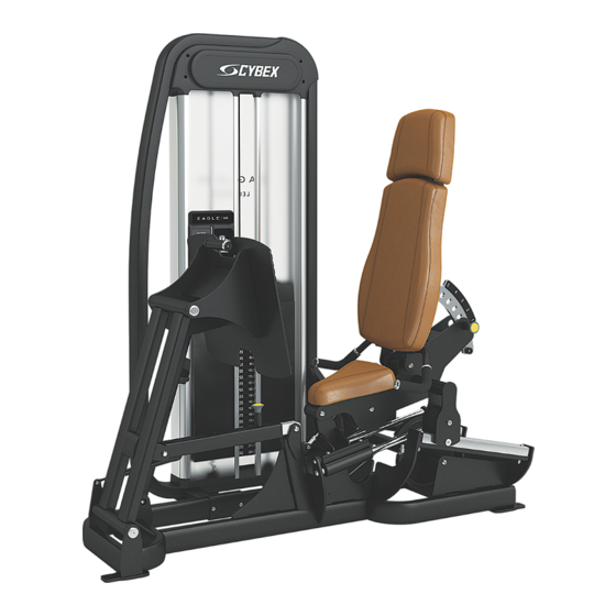
- Page 1 ® NX Leg Press Eagle Owner's Manual Part Number 20040-999-4 AB...
-
Page 3: Table Of Contents
Cybex DISCLAIMER: Cybex International, Inc. makes no representations or warranties regarding the contents of this manual. We reserve the right to revise this document at any time or to make changes to the product described within it without notice or obligation to notify any person of such revisions or changes. -
Page 4: Safety Guidelines And Practices
• Fasteners must have a minimum of 500 lbs. tensile capacity. Cybex recommends .3/8” grade 2 bolts or better. A minimum pull force of 220 lbs/100 kgs is required for each anchor position. -
Page 5: User Safety Precautions
• DO NOT pin weights on selectorized equipment in an elevated position or use the machine if found in this position • DO NOT increase weight resistance on equipment by any means other than those provided by Cybex. • DO NOT wear loose or dangling clothing or jewelry while using equipment. Stay clear of moving parts. -
Page 6: Warnings And Cautions
Caution labels indicate a potentially hazardous situation that could result in serious injury or damage to machine if the precautions are not observed. Contact Cybex Customer Service to replace any worn or damaged labels. Page 6 of 25... -
Page 7: Label Placement
Label Placement The following diagram shows where each label is located. Description DE000023-X 8500-025-X Page 7 of 25... -
Page 8: Assembly
Assembly Machine Specifications Total Weight and Size 20040 Leg press Weight Machine Dimensions at Rest Machine Dimensions in Use 1045Lbs 68” L × 42” W × 73” H 100” L × 42” W × 73” H 474 Kg 172 cm L × 107 cm W × 185 cm H 254 cm L ×... -
Page 9: Environment
Environment Humidity and Static Electricity The unit is designed to function normally in an environment with a relative humidity range of 30% to 75%. The unit can be shipped and stored in a relative humidity range of 10% to 90%. Climatic dry air may cause static electricity. -
Page 10: Assembly Procedure
• Fasteners must have a minimum of 500 lbs. tensile capacity. Cybex recommends .3/8” grade 2 bolts or better. A minimum pull force of 220 lbs/100 kgs is required for each anchor position. - Page 11 2. Remove ten screws securing top covers (front and back) to frame using a Phillips screwdriver. Description 10-32 screw # 8 screw Top cover Back panel 3. Guide front top cover down cable to gain access to pulley assembly. 4. Slide back panel upward and remove. 5.
- Page 12 4. Repeat above step for opposite guide rod. 5. Lean guide rods slightly outward, away from machine. DO NOT put excessive pressure on guide rods, it will damage lower guide rod caps. 6. Slide top weight up and out of the machine and set aside. 7.
- Page 13 Separate Frame 1. Remove four bolts, four locknut, and two connectors securing two halves of the frame using a 7/32” Allen wrench and 9/16” wrench. Description Bolt Connector Locknut 2. Move each half through the doorway to the desired location. Assemble Frame 1.
- Page 14 4. Install each weight plate, one at a time, so wide edge of bushing faces upward (1) and narrow edge of bushing (2) faces downward. Correct: Wide bushing edge upward Incorrect: Narrow bushing edge downward. 5. Slide top weight onto guide rods. 6.
- Page 15 Description Backing Front sheet Weight decals 2. Place decals front sheet in the correct position on weight plates. 3. Insert a guide pin through each hole of the decals front sheet. (A guide pin can be anything that fits through the weight stack hole, such as a weight stack selector pin.) 4.
- Page 16 3. Turn cam assembly to gain access to the cam notch. 4. Install cable end in cam notch. 5. Push the clamp ends together securing cable in place. Description Cable Clamp Cam notch 6. Repeat above procedure for weight cable. Install Guard Plate Install three Phillips head screws securing guard plate to frame using a Phillips screwdriver.
- Page 17 • Fasteners must have a minimum of 500 lbs. tensile capacity. Cybex recommends .3/8” grade 2 bolts or better. A minimum pull force of 220 lbs/100 kgs is required for each anchor position.
-
Page 18: Exercise
Exercise Intended Use The intended commercial use of this machine is to aid exercise and improve general physical fitness. Instructions Read and understand all instructions and warnings prior to using this machine in the Safety section of the Owner’s Manual. Use only in manner depicted. -
Page 19: Maintenance
Not inhale or swallow any cleaning product. Protect surrounding area/clothing from exposure. Use in well ventilated area. Follow all product manufacturer’s warnings. Cybex and its vendors cannot be held responsible for damage or injuries resulting from the use or misuse of cleaning products. -
Page 20: Weekly Procedures
Then Prepare a solution of 10% household bleach (sodium hypochlorite) and 90% water. Dampen a soft white cloth in the solution. Rub gently on the stained area. Dampen a clean soft cloth in water and rinse area. More Difficult Stains If stains are still present, a full strength household bleach may be used. -
Page 21: Yearly Procedures
Tools Required 9/16" Wrench (2) Four types of cable tension adjustment are used on Cybex Strength Systems: Jam Nut Adjustment This type of adjustment uses a jam nut and a tension adjustment nut at the cable cam end as the primary adjustment. - Page 22 Description Qty. Jam nut Tension adjustment nut Rod End Adjustment This type of adjustment uses a socket head cap screw (SHCS) securing a cable rod end bearing to the machine. Primary adjustment is by turning the rod end bearing. The other end of the cable usually contains a roll pin cable adjustment.
-
Page 23: Customer Service
To speak with a customer service representative, call 800-351-3737 (for customers living within the USA) or 847-288-3700 (for customers outside the USA). The following information located on the serial number decal will assist our Cybex representatives in serving you. • Unit Serial Number, Product Name and Model Number •... -
Page 24: Damaged Parts
Provide the model and serial number of your Cybex equipment. At Cybex’s discretion, the technician may request that you return the problem part(s) to Cybex for evaluation and repair or replacement. The technician will assign you a RMA number and will send you an ARS label. The ARS label and the RMA numbers must be clearly displayed on the outside of the package that contains the item(s) to be returned. - Page 25 Columbia Center III - 9525 West Bryn Mawr Ave, Rosemont, IL 60018 • 800-351-3737 • 847-288-3700 • FAX 800-216-8893 www.cybexintl.com...
Need help?
Do you have a question about the Eagle 20040-999-4 AB and is the answer not in the manual?
Questions and answers