Table of Contents
Advertisement
Quick Links
This user's guide provides an overview of the OPT3101 time-of-flight (ToF) proximity sensor evaluation
module (EVM). The OPT3101EVM is a single-pixel implementation of the OPT3101 device consisting of a
printed-circuit board (PCB) and an accompanying software package. The EVM is intended for prototyping
and evaluation. This user's guide includes an overview of the EVM hardware and software in addition to
the schematic diagram, layout, and bill of materials. Throughout this document, the abbreviation EVM and
the term evaluation module are synonymous with the OPT3101EVM.
The following related documents are available through the Texas Instruments web site at www.ti.com.
Introduction to Time-of-Flight and Optical Proximity Sensor
OPT3101 Distance Sensor System Calibration Guide
...................................................................................................................
1
1.1
1.2
2
3
3.1
2
3.2
I
3.3
3.4
3.5
4
4.1
4.2
5
5.1
5.2
5.3
5.4
6
6.1
7
7.1
7.2
7.3
....................................................................................................................
8
8.1
8.2
SBAU309A - February 2018 - Revised June 2018
Submit Documentation Feedback
Table 1. Related Documentation
Document Name
OPT3101 Data Sheet
System Design Guide
...........................................................................................................
..............................................................................................................
..................................................................................................................
...................................................................................................
...........................................................................................
..................................................................................
.................................................................................................
........................................................................................................
...........................................................................................
.............................................................................................................
..................................................................................
.......................................................................................
.............................................................................................
............................................................................................................
®
®
.......................................................................................
......................................................................................
..................................................................................
.....................................................................................
Copyright © 2018, Texas Instruments Incorporated
SBAU309A - February 2018 - Revised June 2018
OPT3101 Evaluation Module
Literature Number
Contents
..............................................................................
........................................................................
.........................................................
...........................................................
........................................................................
........................................................................
List of Figures
User's Guide
SBAS883
SBAU305
SBAU310
.................................
OPT3101 Evaluation Module
3
3
3
4
5
5
5
7
7
8
8
8
9
11
11
11
11
13
17
17
25
25
27
29
31
31
36
1
Advertisement
Table of Contents

Related Manuals for Texas Instruments OPT3101


Summary of Contents for Texas Instruments OPT3101
-
Page 1: Table Of Contents
This user’s guide provides an overview of the OPT3101 time-of-flight (ToF) proximity sensor evaluation module (EVM). The OPT3101EVM is a single-pixel implementation of the OPT3101 device consisting of a printed-circuit board (PCB) and an accompanying software package. The EVM is intended for prototyping and evaluation. - Page 2 ......................Installation Directory ......................Additional Steps ......................Installation Page ...................... Installation Complete ..............OPT3101 Control and Data Ports in Device Manager ................OPT3101EVM Connection Problem Error ....................OPT3101 Profile Selector ........................ Gui Window ..............Composite Plot Showing Amplitude and Distance ............
-
Page 3: Disclaimers
Corp.) that contains > 0.1% of lead titanium zirconium oxide CAS# 12626-81-2 listed in EU REACH as a substance of very high concern. These uses from Texas Instruments do not exceed 1 ton per year. For more information, contact the component manufacturer. -
Page 4: Introduction
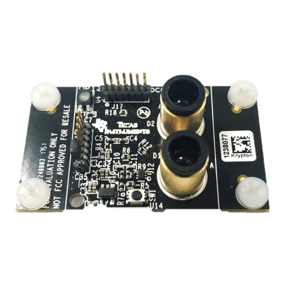
The PCB is a single-pixel system that uses the OPT3101 device for ToF proximity sensing. The PCB connects to a computer running the Latte software through USB. The Latte software allows visualization and logging of the OPT3101 readings, setting... -
Page 5: Opt3101Evm Hardware
The MSP430 registers 2 USB COM ports with the PC it is plugged in to. The OPT3101 Control Port is used for sending control commands to the MSP430. This includes reading and writing registers on the OPT3101 and interfacing with the MSP430 flash storage. -
Page 6: Labeled Opt3101Evm - Top Side
OPT3101EVM Hardware www.ti.com Figure 3. Labeled OPT3101EVM – Top Side Figure 4. Labeled OPT3101EVM – Bottom Side OPT3101 Evaluation Module SBAU309A – February 2018 – Revised June 2018 Submit Documentation Feedback Copyright © 2018, Texas Instruments Incorporated... -
Page 7: Light-Emitting Diode (Led) And Photodiode (Pd) For Tof Measurements
As the introduction states, this EVM is a single-pixel system. There is a single LED-photodiode pair that connects to the OPT3101 and is used for ToF measurements. The EVM uses a 850-nm centroid (860-nm peak) wavelength IR LED (SFH 4550), and a 900-nm peak sensitivity IR photodiode (SFH 213 FA). -
Page 8: Other Components
The following components are also used on the PCB: • The LDO creates a 3.3-V supply, which powers both the MSP430 and the OPT3101. • The programming switch puts the EVM in bootloader mode. This works by holding down the switch during power up. -
Page 9: Installing The Software (Pc Application)
The full installation steps are shown step by step in the following screenshots. Figure 7. Accepting the License Agreement Figure 8. Installation Directory SBAU309A – February 2018 – Revised June 2018 OPT3101 Evaluation Module Submit Documentation Feedback Copyright © 2018, Texas Instruments Incorporated... -
Page 10: Additional Steps
Software Installation www.ti.com Figure 9. Additional Steps Figure 10. Installation Page OPT3101 Evaluation Module SBAU309A – February 2018 – Revised June 2018 Submit Documentation Feedback Copyright © 2018, Texas Instruments Incorporated... -
Page 11: Using The Evm
Figure 12. OPT3101 Control and Data Ports in Device Manager If the OPT3101 Control and OPT3101 Data ports do not show up in the device manager when the board is plugged in or the device drivers show up differently than pictured in... -
Page 12: Opt3101Evm Connection Problem Error
Using the EVM www.ti.com Figure 13. OPT3101EVM Connection Problem Error If multiple OPT3101 profiles are downloaded and saved onto your PC, you will be asked to select a profile before the GUI will launch. Figure 14 shows what the profile selector looks like. -
Page 13: Using Latte Software
Clicking the Start Capture button begins capture. This sends a capture start command over the OPT3101 Control Port to the MSP430 on the EVM. The EVM then begins streaming data over the OPT3101 Data Port. This data is displayed live on the left side of the window. Distance is plotted on the graph. The axis of the plot can be changed by right clicking on the plot itself. -
Page 14: Gui Controls Panel
EVM to 2 ksps. In 3 register mode, there is too much data to send at higher speeds than 2 ksps. 2 register mode omits the 0Ah register. The OPT3101 device can run at up to 4 ksps, but due to the speed of the MSP430, the maximum speed of the EVM is 3 ksps. -
Page 15: Gui Data Capture Fields
The derived data from the FRAME_COUNT0, FRAME_COUNT1, and FRAME_COUNT2 registers. Indicates the current data frame that is being received from the OPT3101. This value starts at 0 and increments with each frame the OPT3101 reads. After reaching 31 this value loops back to 0. -
Page 16: Composite Plot Showing Amplitude And Distance
If capture is running this data updates in real-time along with the data in the Live column. OPT3101 Evaluation Module SBAU309A – February 2018 – Revised June 2018 Submit Documentation Feedback Copyright © 2018, Texas Instruments Incorporated... -
Page 17: Troubleshooting
® ® This section outlines the manual driver installation process. If you are using Windows 7 or if the Windows device manager shows the OPT3101 Control and OPT3101 Data as other devices instead of COM ports as shown in Figure 17, use the following steps. - Page 18 Troubleshooting www.ti.com 3. Click the Update Driver… button. 4. Click Browse my computer for driver software OPT3101 Evaluation Module SBAU309A – February 2018 – Revised June 2018 Submit Documentation Feedback Copyright © 2018, Texas Instruments Incorporated...
- Page 19 5. Click Let me pick from a list of device drivers on my computer. 6. Select Show All Devices and click the Next button. SBAU309A – February 2018 – Revised June 2018 OPT3101 Evaluation Module Submit Documentation Feedback Copyright © 2018, Texas Instruments Incorporated...
- Page 20 Troubleshooting www.ti.com 7. Click the Have Disk… button. 8. Click the Browse… button. OPT3101 Evaluation Module SBAU309A – February 2018 – Revised June 2018 Submit Documentation Feedback Copyright © 2018, Texas Instruments Incorporated...
- Page 21 Troubleshooting www.ti.com 9. Navigate to “C:\Users\<username>\Documents\Texas Instruments\Latte\projects\opt3101\drivers” and choose MSP430_CDC. Click the Open button. 10. Click the OK button SBAU309A – February 2018 – Revised June 2018 OPT3101 Evaluation Module Submit Documentation Feedback Copyright © 2018, Texas Instruments Incorporated...
- Page 22 Troubleshooting www.ti.com 11. Select OPT3101 Control and click the Next button. 12. Click the Yes button. OPT3101 Evaluation Module SBAU309A – February 2018 – Revised June 2018 Submit Documentation Feedback Copyright © 2018, Texas Instruments Incorporated...
- Page 23 13. The driver should now install properly. 14. Now repeat this process (steps 1 to 13) for OPT3101 Data. All steps are the same except for step 2 and step 11. In step 2 make sure to right click OPT3101 Data instead of OPT3101 Control. Likewise, on step 11 make sure to select OPT3101 Data instead of OPT3101 Control when installing the driver as the following figure shows.
- Page 24 15. When the OPT3101 Data driver is installed, you will see the following message. 16. OPT3101 Control and OPT3101 Data should now appear in the device manager under Ports (COM & LPT) as the following image shows. OPT3101 Evaluation Module SBAU309A –...
-
Page 25: Opt3101Evm Schematics, Layout, And Bom
This section contains the schematic diagrams, printed circuit board (PCB) layouts and complete bill of materials for the OPT3101EVM. OPT3101EVM Schematics Figure 18 illustrates the EVM schematics. SBAU309A – February 2018 – Revised June 2018 OPT3101 Evaluation Module Submit Documentation Feedback Copyright © 2018, Texas Instruments Incorporated... -
Page 26: Evm Schematic
100nF 100nF 10pF VSS_IN USB_5V 4.7uF 100nF VSS_IN TPD2E001DRLR 220nF 220nF VSS_IN VSS_IN USB_Connector Micro USB-B Figure 18. EVM Schematic OPT3101 Evaluation Module SBAU309A – February 2018 – Revised June 2018 Submit Documentation Feedback Copyright © 2018, Texas Instruments Incorporated... -
Page 27: Opt3101Evm Pcb Layout
Figure 22 illustrate the EVM PCB layouts. Figure 19. PCB Layout Top Layer Figure 20. PCB Layout Inner Layer 1 SBAU309A – February 2018 – Revised June 2018 OPT3101 Evaluation Module Submit Documentation Feedback Copyright © 2018, Texas Instruments Incorporated... -
Page 28: Pcb Layout Inner Layer
OPT3101EVM Schematics, Layout, and BOM www.ti.com Figure 21. PCB Layout Inner Layer 2 Figure 22. PCB Layout Bottom Layer OPT3101 Evaluation Module SBAU309A – February 2018 – Revised June 2018 Submit Documentation Feedback Copyright © 2018, Texas Instruments Incorporated... -
Page 29: Opt3101Evm Bill Of Materials
SFH213FA SFH 4550 OSRAM EMITTER IR 860NM 100MA RADIAL SFH 213 FA SFH213FA SFH 213 FA OSRAM PHOTODIODE 5MM 900NM SBAU309A – February 2018 – Revised June 2018 OPT3101 Evaluation Module Submit Documentation Feedback Copyright © 2018, Texas Instruments Incorporated... - Page 30 49n_a FLASH 48VQFN TPD2E001DRLR SOT553 TPD2E001DRLR Texas Instruments TVS DIODE 5.5VWM 100VC SOT5 OPT3101-QFN28 QFN50P400X500X10 OPT3101RHFR Texas Instruments OPT3101 0_EPA-29N OPT3101 Evaluation Module SBAU309A – February 2018 – Revised June 2018 Submit Documentation Feedback Copyright © 2018, Texas Instruments Incorporated...
-
Page 31: Appendix
(IDE) window that is minimized when TI-Latte is launched. The IDE window allows advanced users to customize the existing scripts or write new scripts SBAU309A – February 2018 – Revised June 2018 OPT3101 Evaluation Module Submit Documentation Feedback Copyright © 2018, Texas Instruments Incorporated... -
Page 32: Ide Window
Customization of the 01-variableSetup.py scripts allows for initialization paremeters of the device to be changed. Latte also provides functionality to write custom Python scripts for testing and evaluation purposes with the OPT3101. The example scripts provided can be used as a reference to write custom scripts. - Page 33 Running the Scripts After launching Latte, expand the OPT3101 directory on the left hand side of the window under Files by clicking the triangle to the left of the directory name. This displays the calibData, drivers, and OPT3101EVMrevE3_Demo folders. Further expanding the OPT3101EVMrevE3_Demo...
-
Page 34: Demo Scripts In Latte Software
Appendix www.ti.com Figure 24. Demo Scripts in Latte Software OPT3101 Evaluation Module SBAU309A – February 2018 – Revised June 2018 Submit Documentation Feedback Copyright © 2018, Texas Instruments Incorporated... -
Page 35: After Running Devinit.py
Additional info is also displayed in the log window in the lower left- hand corner of the main window. Figure 25 shows the register view and log output added to the main window. Figure 25. After Running devInit.py SBAU309A – February 2018 – Revised June 2018 OPT3101 Evaluation Module Submit Documentation Feedback Copyright © 2018, Texas Instruments Incorporated... -
Page 36: Capture Gui: Launchgui.py
Capture GUI: launchGUI.py A liveview GUI window is launched when running the devInit.py script. This allows data from the OPT3101 to be viewed on a graph in real time. The GUI is created in the launchGUI.py example script. When running devInit.py, the launchGUI.py script is automatically run. However, if the GUI window is closed it can be re-launched by directly running the launchGUI.py script. - Page 37 SBAU309A – February 2018 – Revised June 2018 OPT3101 Evaluation Module Submit Documentation Feedback...
- Page 38 IMPORTANT NOTICE FOR TI DESIGN INFORMATION AND RESOURCES Texas Instruments Incorporated (‘TI”) technical, application or other design advice, services or information, including, but not limited to, reference designs and materials relating to evaluation modules, (collectively, “TI Resources”) are intended to assist designers who are developing applications that incorporate TI products;...
- Page 39 STANDARD TERMS FOR EVALUATION MODULES Delivery: TI delivers TI evaluation boards, kits, or modules, including any accompanying demonstration software, components, and/or documentation which may be provided together or separately (collectively, an “EVM” or “EVMs”) to the User (“User”) in accordance with the terms set forth herein.
- Page 40 FCC Interference Statement for Class B EVM devices NOTE: This equipment has been tested and found to comply with the limits for a Class B digital device, pursuant to part 15 of the FCC Rules. These limits are designed to provide reasonable protection against harmful interference in a residential installation.
- Page 41 【無線電波を送信する製品の開発キットをお使いになる際の注意事項】 開発キットの中には技術基準適合証明を受けて いないものがあります。 技術適合証明を受けていないもののご使用に際しては、電波法遵守のため、以下のいずれかの 措置を取っていただく必要がありますのでご注意ください。 1. 電波法施行規則第6条第1項第1号に基づく平成18年3月28日総務省告示第173号で定められた電波暗室等の試験設備でご使用 いただく。 2. 実験局の免許を取得後ご使用いただく。 3. 技術基準適合証明を取得後ご使用いただく。 なお、本製品は、上記の「ご使用にあたっての注意」を譲渡先、移転先に通知しない限り、譲渡、移転できないものとします。 上記を遵守頂けない場合は、電波法の罰則が適用される可能性があることをご留意ください。 日本テキサス・イ ンスツルメンツ株式会社 東京都新宿区西新宿6丁目24番1号 西新宿三井ビル 3.3.3 Notice for EVMs for Power Line Communication: Please see http://www.tij.co.jp/lsds/ti_ja/general/eStore/notice_02.page 電力線搬送波通信についての開発キットをお使いになる際の注意事項については、次のところをご覧ください。http:/ /www.tij.co.jp/lsds/ti_ja/general/eStore/notice_02.page 3.4 European Union 3.4.1 For EVMs subject to EU Directive 2014/30/EU (Electromagnetic Compatibility Directive): This is a class A product intended for use in environments other than domestic environments that are connected to a low-voltage power-supply network that supplies buildings used for domestic purposes.
- Page 42 Notwithstanding the foregoing, any judgment may be enforced in any United States or foreign court, and TI may seek injunctive relief in any United States or foreign court. Mailing Address: Texas Instruments, Post Office Box 655303, Dallas, Texas 75265 Copyright © 2018, Texas Instruments Incorporated...
- Page 43 IMPORTANT NOTICE FOR TI DESIGN INFORMATION AND RESOURCES Texas Instruments Incorporated (‘TI”) technical, application or other design advice, services or information, including, but not limited to, reference designs and materials relating to evaluation modules, (collectively, “TI Resources”) are intended to assist designers who are developing applications that incorporate TI products;...
- Page 44 Mouser Electronics Authorized Distributor Click to View Pricing, Inventory, Delivery & Lifecycle Information: Texas Instruments OPT3101EVM...
Need help?
Do you have a question about the OPT3101 and is the answer not in the manual?
Questions and answers