Table of Contents
Advertisement
Quick Links
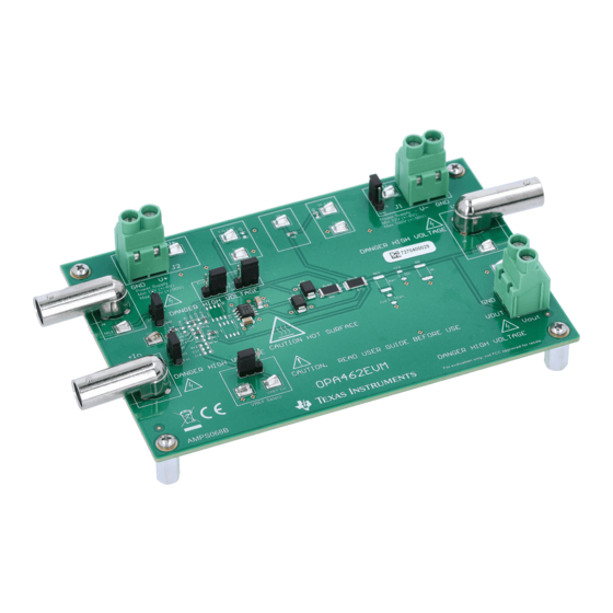
This user's guide describes the characteristics, operation, and use of the evaluation module (EVM) for the
OPA462. The EVM is designed to evaluate the performance of the devices in both single and dual-supply
configurations. This document also includes the schematic, printed circuit board (PCB) layout, and a bill of
materials (BOM). Throughout this document the terms evaluation board, evaluation module, and EVM are
synonymous with OPA462EVM.
Danger: HIGH VOLTAGE! This evaluation board is intended for
professional use only. It has exposed high voltages. Do not
operate this board without proper high-voltage/high-current safety
practices. Read
SBOU175 – October 2019
Submit Documentation Feedback
WARNING
Section 1.4
before using the EVM.
Copyright © 2019, Texas Instruments Incorporated
User's Guide
SBOU175 – October 2019
OPA462EVM
1
OPA462EVM
Advertisement
Table of Contents

Related Manuals for Texas Instruments OPA462EVM


Summary of Contents for Texas Instruments OPA462EVM
- Page 1 Danger: HIGH VOLTAGE! This evaluation board is intended for professional use only. It has exposed high voltages. Do not operate this board without proper high-voltage/high-current safety practices. Read Section 1.4 before using the EVM. SBOU175 – October 2019 OPA462EVM Submit Documentation Feedback Copyright © 2019, Texas Instruments Incorporated...
-
Page 2: Table Of Contents
Related Documentation ......................... Jumper Table ......................OPA462EVM BOM Trademarks PowerPAD is a trademark of Texas Instruments. All other trademarks are the property of their respective owners. OPA462EVM SBOU175 – October 2019 Submit Documentation Feedback Copyright © 2019, Texas Instruments Incorporated... -
Page 3: Overview
This device is designed to avoid phase inversion problems that are typically found in similar op amps. The OPA462 is unity-gain stable, and comes in an SO PowerPAD™ package. OPA462EVM The OPA462EVM is intended to provide basic functional evaluation of the OPA462. The EVM provides the following features: •... -
Page 4: Getting Started
Power Supplies The OPA462EVM can be configured from ±6 V to ±90 V for dual supply operation, or from 12 V to 180 V for single-supply operation. Shorting pins 2 and 3 of J5 sets the EVM to single supply, and shorting pins 1 and 2 of J5 sets up the EVM for dual supplies. -
Page 5: Status Flag
2.6.1 Circuit Protection The OPA462EVM is protected from inductive surges and power supply transients with the use of Schottkey diodes on the amplifier output and transient voltage suppressors on the power supply inputs. See D1, D2, D3 and D4 on the schematic shown in... -
Page 6: Application Circuits
Improved Howland Current Pump The OPA462EVM can be configured as an improved Howland current pump that provides an output current proportional to a single- or differential-input voltage. The improved Howland current pump is described and analyzed in section 3 of the... -
Page 7: Improved Howland Current Pump Output-Voltage Compliance Range
A 20-mA dc current source using the OPA462 has been demonstrated, and will now be used to show how a 20-mA peak ac-current waveform can be realized. SBOU175 – October 2019 OPA462EVM Submit Documentation Feedback Copyright © 2019, Texas Instruments Incorporated... -
Page 8: Improved Howland Current Pump Applied As A Peak Ac-Current Generator
The OPA462EVM has a number of positions where component may be added to stabilize the various OPA462 amplifier and improved Howland current pump configurations that are supported by the EVM. -
Page 9: Schematic, Pcb Layout, And Bill Of Materials
Schematic, PCB Layout, and Bill of Materials www.ti.com Schematic, PCB Layout, and Bill of Materials This section discusses the OPA462EVM hardware schematics, PCB layout and jumper configurations. EVM Schematic Figure 4 depicts the complete OPA46xEVM schematic. Op Amp Supplies and Bulk Decoupling... -
Page 10: Evm Default Configuration
Schematic, PCB Layout, and Bill of Materials www.ti.com EVM Default Configuration The OPA462EVM ships in a standard amplifier configuration with a noninverting gain of 11. Figure 5 shows the schematic for the default configuration. Any components shown on the complete schematic but not on this schematic are optional and not installed. -
Page 11: Pcb Layout
Figure 6. OPA462EVM PCB Layout NOTE: Board layout is not to scale. This figure is intended to show how the board is laid out, and is not intended to be used for manufacturing OPA462EVM PCBs. SBOU175 – October 2019 OPA462EVM Submit Documentation Feedback Copyright ©... -
Page 12: Bill Of Materials
FID1, FID2, FID3 Optional-Not installed Q1, Q2 JFET, 2-CH, N-CH, V, A, SOIC-8 IF1322A InterFET Optional-Not installed R5, R11, R12 Optional-Not installed R9, R10 Optional-Not installed OPA462EVM SBOU175 – October 2019 Submit Documentation Feedback Copyright © 2019, Texas Instruments Incorporated... - Page 13 TI products. TI’s provision of these resources does not expand or otherwise alter TI’s applicable warranties or warranty disclaimers for TI products. TI objects to and rejects any additional or different terms you may have proposed. IMPORTANT NOTICE Mailing Address: Texas Instruments, Post Office Box 655303, Dallas, Texas 75265 Copyright © 2022, Texas Instruments Incorporated...
Need help?
Do you have a question about the OPA462EVM and is the answer not in the manual?
Questions and answers