Table of Contents
Advertisement
Quick Links
Advertisement
Table of Contents

Related Manuals for Redexim Verti-Drain 7516


Summary of Contents for Redexim Verti-Drain 7516
- Page 1 Operator and Parts Redexim manual Verti-Drain® Model 7516 Serial number: NOTE: IN ORDER TO ENSURE THE SAFE USE AND TO ACHIEVE THE BEST PERFORMANCE, IT IS ESSENTIAL THAT THIS OPERATORS MANUAL IS CAREFULLY READ BEFORE THE VERTI-DRAIN IS USED. 0720 English 911.120.451...
-
Page 2: Foreword
FOREWORD Congratulations on the purchase of your VERTI-DRAIN. To ensure the safe and lasting operations of this VERTI-DRAIN you (and anyone using the machine) should read and understand this user’s manual. A complete knowledge of the contents of the manual is necessary in order to ensure the safe use of this machine. -
Page 3: Safety Instruction
SAFETY INSTRUCTIONS Always use the VERTI-DRAIN with the correct tractor as described in the technical information The user is responsible for a safe Tractor/VERTI-DRAIN combination. The combination must be tested for noise, safety, risk and easy usage. It is also necessary to draw up user instructions. -
Page 4: Table Of Contents
CONTENTS Par. Description Page Foreword Guarantee conditions Registration card Safety instruction Technical specification First setup, Lifting machine from pallet General controls PTO length Use of PTO Slipclutch information and maintenance Working depth adjustment Tine angle adjustment Groundspeed Starting procedures General usage of Verti-Drain 10.0 Transport of Verti-Drain 11.0... -
Page 5: Technical Specification
1.0 TECHNICAL SPECIFICATIONS Model 7516 Working width 1.60 mtr (5’4”) Working depth Up to 400 mm (16”) Tractor speed @ 500 rev’s at PTO Hole spacing 65 mm (2-1/2”) Up to 0.70 km/h (0.45 mph) Hole spacing 130mm( 5”) Up to 1.40 km/h (0.90 mph) Hole spacing 195mm(7-1/2”) Up to 2.10 km/h (1.35 mph) PTO speed... -
Page 6: First Setup, Lifting Machine From Pallet
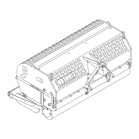
2.0 FIRST SETUP, LIFTING MACHINE FROM PALLET The machine stands vertically up on the pallet. To remove the pallet and get the machine horizontal on the ground, handle as follows (see fig.1 ): 1. Open the rear cover 2. Connect a cable to lift point * ensure the cable/crane/lift truck can lift minimum 4000 Kg.(9000 lbs). -
Page 7: General Controls
3.0 GENERAL CONTROLS In fig.2. some key details of the machine are shown, as follows: 1. Safety decall RA, before using machine read manual. Decall is located at the toolbox with manuals and combi-tool. 2. Safety decall RB, Keep 4 mtr (14' ) distance to the machine 3. -
Page 8: Pto
4.0 PTO. The PTO is a very important item. It drives the machine from the tractor and ensures the safe operations when correctly maintained and installed. The PTO shaft has its own CE certification. Read the PTO shaft manual, which is connected to the shaft itself 4.1 PTO LENGTH. -
Page 9: Use Of Pto
4.2 USE OF PTO For the correct use of the PTO, the following items need to be checked: 1. During work the angle of the joints may never exceed 30 degrees 2. The joints have to be in line all the time 3. -
Page 10: Working Depth Adjustment
5.0 WORKING DEPTH ADJUSTMENT The working depth can be adjusted when the machine is lifted from the ground as follows, see fig. 4: Unscrew nuts 1 at each side of the machine one turn. Screw spindle 3 in or out. Every revolution is 4 mm (0.160"). -
Page 11: Groundspeed
@ From 90 to 75 degrees means more "kick action". This is advised for solid tines, depending on ground conditions, tine size and customer requirements. @ The angle of 90 degrees means that the tines penetrate perpendicular into the ground. This is only true if the machine is correctly set, see fig.1. -
Page 12: Starting Procedures
8.0 STARTING PROCEDURES The starting procedure is VERY important. If the start up is not done as described hereunder, serious damage to the machine may occur. Proceed as follows, see fig.7.: 1. Drive to the spot you want to start the operation. 2. -
Page 13: General Usage Of Verti-Drain
@ NEVER drive backwards, when the lowest tines are less than 120 mm (5") above the ground. If the tines get caught, serious damage will appear on the machine. @ Do not use a hydraulic top link. 9.0 GENERAL USAGE OF VERTI-DRAIN The VERTI-DRAIN can only be used when the circumstances are right. -
Page 14: Problem Analysis
12.0 PROBLEM ANALYSIS Machine vibrates Crankshaft rotates irregular Machine not at 90 degrees. PTO joint angles different. PTO joints not in line. Tough circumstances Adjust working depth. Use thinner/ shorter tines. If dry, irrigate first. Solid/ hollow tines Wrong tine Change tine, use shorter one. -
Page 15: Maintenance
Look closely at machine Grease spindles front roller 14.0 EU-Declaration We, Redexim Utrechtseweg 127 3702 AC Zeist Holland, hereby declare fully on our authority that the product: VERTI-DRAIN 7516, WITH MACHINE NUMBER AS INDICATED ON THE MACHINE AND IN THIS MANUAL, to which this declaration applies, has been manufactured in line with NEN-EN 12100-1, NEN 12100-2 and NEN-EN 294, according to the stipulations of: The Machine Directive 98/37/EG. -
Page 16: Technical Information
15.0 TECHNICAL INFORMATION Generally speaking, this Verti-Drain is not a complicated machine. A couple of technical items will be explained. If you still have questions, please contact your dealer, who is willing to assist you 15.1 TORQUE SETTINGS In fig.8., the torque settings of the most important bolts/nuts are given. For the ones the torque setting is not mentioned, please be sure that they are tightened as a similar size bolt/nut would be tightened. -
Page 17: The Crankshaft
15.2 THE CRANKSHAFT In fig.9. the assembly of the crankshaft is given. Also look at the spare part page for a more clear view and setup. On a 7516 the angle between the handles on the gearbox should be 60 degrees. 15.2.1 REPLACING THE TRANSMISSION OIL SEAL In fig.9. -
Page 18: Alignment Of An Element
3. Repeat this operation with the adjacent crank and continue this way till the crankshaft will operate more smoothly. @ After any repair on the crankshaft, the crankshaft nuts should be checked regularly, see 12.0 @ Don’t assemble the cranks at the wrong side of the machine. See the spare part for the right part numbers 15.3 ALIGNMENT OF AN ELEMENT In the event that an element is no longer in line with the adjacent elements, the alignment can be... -
Page 19: Mounting The Wheelkit To The Machine
16.0.1 MOUNTING THE WHEELKIT TO THE MACHINE Work as follows, see fig.10.: 1. Unpack all parts and lay them down. 2. Put machine horizontal on a hard floor with locked rear roller and in deepest work position. 3. Assemble pins Q in main frame each side and tighten nut inside. 4. -
Page 20: Options, Tines
Never disconnect the hoses from tractor when machine is raised from the ground. Always ensure that machine is tight on the ground with locked rear roller supports and relieved oil pressure, before disconnecting the hoses. (see also par.11.0) When the working depth is adjusted, always reset the machine at 90 degrees with toplinks. Check bolts/nuts regularly. -
Page 21: Hollow Tines
If the root system is weak, don’t try to break the soil much deeper than the root system. Adjust the working depth till the penetration is about 75 mm (3”) more than the root system depth. This allows the roots to grow deeper. Next time penetrate deeper. Using this method will safe you from damaging the turf and will establish a healthy root system. - Page 22 Assembling the core collector itself: Assemble supports 17 with eye bolts 9 and nuts 10/11 to the main collector plate 1 Screw the side panels U with bolts 7 and Bushes 8 to the main collector plate 1 Assemble the rubber strip 12 with bolts 13, washers 14 and nuts 6 to the plate 1 Assemble all the sheet springs 4 , well aligned, to the main plate 1.
-
Page 23: Auxiliary Spring Kit
If the area isn’t clean, check the gap between the rubber seal strip N and the blade spring tension T. Extra weight on top of the core collector may help as well. 16.1.4 AUXILIARY SPRING KIT In some cases, people want more pre tension on the draw rod springs. A complete spring kit per draw rod has the part number 211.752.004.. -
Page 24: Rear Roller Extension Kit
When we apply too much spring force on the tines ( especially in combination with the 12 mm ( ½”)), we may destroy the hole edge, since the spring is pulling hard at the moment the tines are leaving the ground. Extra spring force is not advised for such applications. 16.1.5 Rear roller extension kit The kit 211.752.002 can be mounted at the standard rear roller supports and moves the roller further away from the moving parts inside the machine.
Need help?
Do you have a question about the Verti-Drain 7516 and is the answer not in the manual?
Questions and answers