
Subscribe to Our Youtube Channel
Related Manuals for Redexim VERTI-DRAIN 7416


Summary of Contents for Redexim VERTI-DRAIN 7416
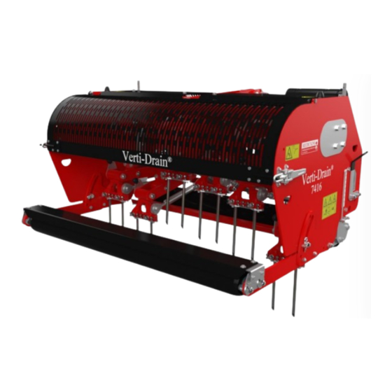
- Page 1 User manual VERTI-DRAIN 7416 Translation of the original user manual 2201 English 911.120.441 EN Kwekerijweg 8 | 3709JA | Zeist | The Netherlands | T: +31 (0)306 933 227 redexim@redexim.com www.redexim.com...
-
Page 2: Eu - Declaration Of Conformity
EU – DECLARATION OF CONFORMITY Redexim Handel- en Exploitatie Maatschappij B.V. Kwekerijweg 8 3709 JA Zeist, The Netherlands declare that this “EU - DECLARATION OF CONFORMITY” is issued under our sole responsibility and belongs to the following product: VERTI-DRAIN® WITH MACHINE NUMBER AS INDICATED ON THE MACHINE AND IN... -
Page 3: Declaration Of Conformity
UK – DECLARATION OF CONFORMITY Redexim Handel- en Exploitatie Maatschappij B.V. Kwekerijweg 8 3709 JA Zeist, The Netherlands declare that this “UK - DECLARATION OF CONFORMITY” is issued under our sole responsibility and belongs to the following product: VERTI-DRAIN® WITH MACHINE NUMBER AS INDICATED ON THE MACHINE AND IN... -
Page 4: Foreword
FOREWORD Congratulations on the purchase of your VERTI-DRAIN. To ensure the safe and lasting operations of this VERTI-DRAIN you (and anyone using the machine) should read and understand this user's manual. A complete knowledge of the contents of the manual is necessary in order to ensure the safe use of this machine. -
Page 5: Safety Instruction
SAFETY INSTRUCTIONS Always use the VERTI-DRAIN with the correct tractor as described in the technical information The user is responsible for a safe Tractor/VERTI-DRAIN combination. The combination must be tested for noise, safety, risk and easy usage. It is also necessary to draw up user instructions. -
Page 6: Table Of Contents
CONTENTS Paragraph Description Page EU – DECLARATION OF CONFORMITY UK – DECLARATION OF CONFORMITY Foreword Guarantee conditions Registration card Safety instruction Technical specification First setup, lifting machine from pallet Safety stickers PTO length Use of PTO Working depth adjustment Tine angle adjustment Ground speed Starting procedures General usage of Verti-Drain... -
Page 7: Technical Specification
TECHNICAL SPECIFICATIONS Model 7416 1.60 m (63”) Working width Tot 350 mm (14”) Working depth Tractor speed @ 500 rev’s at Hole spacing 65 mm (2-1/2”) Up to 0.85 km/h (0.55 mph) Hole spacing 130 mm ( 5”) Up to 1.75 km/h (1.10 mph) Hole spacing 195 mm (7-1/2”) Up to 2.50 km/h (1.56 mph) PTO speed: (max) -
Page 8: First Setup, Lifting Machine From Pallet
Fig. 1 2.0 FIRST SETUP, LIFTING MACHINE FROM PALLET The machine stands vertically up on the pallet. To remove the pallet and get the machine horizontal on the ground, handle as follows (see fig.1): 1. Open the rear cover 2. Connect a cable to lift point * Ensure the cable/crane/lift truck can lift minimum 2000 Kg.(5000 lbs). -
Page 9: Safety Stickers
3.0 SAFETY STICKERS Safety stickers are located on both sides of the machine. These safety stickers must always be clearly visible and legible and must be replaced if they have become damaged (see Figure 2). Fig. 2 In case of maintenance, adjustments and repair, always switch OFF the engine of the towing vehicle and the PTO. -
Page 10: Pto
4.0 PTO The PTO is a very important item. It drives the machine from the tractor and ensures the safe operations when correctly maintained and installed. The PTO shaft has its own CE certification. Read the PTO shaft manual, which is connected to the shaft itself. For specific adjustments see the details given on the PTO page in the parts book. -
Page 11: Use Of Pto
4.2 USE OF PTO For the correct use of the PTO, the following items need to be checked: 1. During work the angle of the joints may never exceed 30 degrees 2. The joints have to be in line all the time 3. -
Page 12: Tine Angle Adjustment
6.0 TINE ANGLE ADJUSTMENT All pins can simultaneously be adjusted with 2 handles 1 located on both sides of the machine; see fig. 5. Lift the machine above the ground and loosen clamping handle / bolts 2 on both sides of the machine. -
Page 13: Starting Procedures
In Fig.6., a graph is drawn in which the relation between the ground speed, the gear setting and the hole spacing is given. If the tractor ground speed is known at 500 rpm's of the PTO, the hole spacing can be determined at different gearbox settings. @ If the machine is not set correctly behind the tractor, see fig.1., different angles at the PTO may cause vibration into the drive line of the VERTI-DRAIN. - Page 14 5. Move to the next spot and start again as described above. @ It is absolutely necessary to proceed as described above. If the machine is put into the ground first, without the PTO running, serious damage may occur. @The machine needs to be lowered GENTLY. @ Be careful with driving backwards.
-
Page 15: General Usage Of Verti-Drain
9.0 GENERAL USAGE OF VERTI-DRAIN The VERTI-DRAIN can only be used when the circumstances are right. Check the following items: 1. Are there any loose objects on the field? If so, these must be removed first. 2. Are there any slopes? The maximum slope for the VERTI-DRAIN is 20 degrees. Always operate the VERTI-DRAIN from the top to the bottom of a slop. -
Page 16: Problem Analysis
12.0 PROBLEM ANALYSIS Machine vibrates Crankshaft rotates irregular Machine not at 90 degrees PTO joint angles different PTO joints not in line Tough circumstances Adjust working depth Use thinner/ shorter tines If dry, irrigate first Solid/ hollow tines Wrong tine Change tine, use shorter one are bending/breaking Use solids first before hollow to break... -
Page 17: Maintenance
Crankshaft bearing collapsed Incorrect assembled after repair. Remove, clean, use Loctite Rear roller shacking Rear roller locked Unlock Change speed and PTO rev’s Rear roller up with hollow coring Put roller free on the ground Tough circumstances Change machine settings. 13.0 MAINTENANCE Pre-Delivery-Inspection Check bolts/ nuts... -
Page 18: Technical Information
14.0 TECHNICAL INFORMATION Generally speaking, this Verti-Drain is not a complicated machine. A couple of technical items will be explained. If you still have questions, please contact your dealer, who is willing to assist you. Fig. 8 14.1 TORQUE SETTINGS In fig.8., the torque settings of the most important bolts/nuts are given. -
Page 19: The Crankshaft
Fig. 9 14.2 THE CRANKSHAFT In fig.9. the assembly of the crankshaft is given. Also look at the spare part page for a more clear view and setup. On a 7416 the angle between the handles on the gearbox should be 60 degrees. -
Page 20: Replacing Of A Crank And Crank Bearing
14.2.2. REPLACEMENT OF A CRANK WITH BEARING Replacing a crank is necessary when it is cracked or when the big end nuts start to come loose on a regular base. Either the crank bearing, the crank bearing fitting or the big end pin holes in the crank are damaged. -
Page 21: Options, Core Collector
Fig. 10 15.0 OPTIONS, CORE COLLECTOR An easy mountable core collector is available for the 7416. The part number is 9200080. ASSEMBLING INSTUCTIONS ( see Fig 10): • Preparation of the Verti-Drain: - Fit eye bolts 24 to the main frame 26 - Assemble bushes 15 with the new longer bolts 18 to the rear roller supports. - Page 22 USER INSTRUCTIONS: When the core collector and the Verti-Drain are well prepared, the core collector supports 17 can be slide (X) onto the bushes 15. Secure it with R pins 19. The rear roller is of the ground, when the core collector is attached. It the clearance is not enough, do NOT remove the rear roller (since the weight is needed) but turn the roller up by taking on bearing bolt out.
-
Page 23: Options, Turf Hold Down Kit
7416. One with fingers lining up with the 12 mm ( ½”) holes of the tine holder ( part # 211.741.002) and one with finger lining up with the 18 mm (3/4”) holes (part # 211.741.004). As a standard the Verti-Drain 7416 already has a pre-mounted main beam the turf hold-down fingers can be mounted on. -
Page 24: Options, Tines
15.2 OPTIONS, TINES Tines are essential for the correct working of the machine. Several tines are available for this machine, see the spare part pages for a total overview. Generally speaking, tines can be divided into two categories: Solids and Hollows. We advise using genuine tines, since they are fully adapted to the machine. -
Page 25: Hollow Tines
Use always tines with the same length and size. Replace a bent tine immediately. When this is not done, the machine can be unstable. Don’t use any thicker/ longer tines as what is offered by Shorter (worn) tines can be used in case shallower penetration is required. The machine doesn’t need to be adjusted that much at that time. -
Page 26: Option, Needle Tines
15.3 OPTIONS, NEEDLE TINES With the needle tines, we can create many holes that are hardly noticeable. A special adapter is required to mount 8 needle tine per tine head from the machine, see fig. 13, left. The adapter blocks are bolted against the bottom of the tine holder with two bolts D. The mark (drilled centre points) should face to the centre of the machine.
Need help?
Do you have a question about the VERTI-DRAIN 7416 and is the answer not in the manual?
Questions and answers