Table of Contents
Advertisement
Quick Links
Operating and Parts
manual
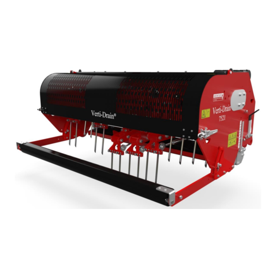
Verti-Drain®
Model 7521
Serial number:
Translation of the original operating instructions
IN ORDER TO ENSURE THE SAFE USE AND TO ACHIEVE THE BEST
PERFORMANCE, IT IS ESSENTIAL THAT THIS OPERATING MANUAL
IS CAREFULLY READ BEFORE THE VERTI-DRAIN IS USED.
NOTE:
1735 English 911.120.461
Kwekerijweg 8
3709JA Zeist
The Netherlands
T: (31)306933227
F: (31)306933228
E:
verti-drain@redexim.com
www.redexim.com
Advertisement
Table of Contents

Related Manuals for Redexim Verti-Drain 7521


Summary of Contents for Redexim Verti-Drain 7521
- Page 1 3709JA Zeist The Netherlands Model 7521 T: (31)306933227 F: (31)306933228 Serial number: verti-drain@redexim.com www.redexim.com Translation of the original operating instructions NOTE: IN ORDER TO ENSURE THE SAFE USE AND TO ACHIEVE THE BEST PERFORMANCE, IT IS ESSENTIAL THAT THIS OPERATING MANUAL IS CAREFULLY READ BEFORE THE VERTI-DRAIN IS USED.
-
Page 2: Foreword
FOREWORD Congratulations on the purchase of your VERTI-DRAIN. To ensure the safe and lasting operations of this VERTI-DRAIN you (and anyone using the machine) should read and understand this user’s manual. A complete knowledge of the contents of the manual is necessary in order to ensure the safe use of this machine. -
Page 3: Safety Instruction
SAFETY INSTRUCTIONS Always use the VERTI-DRAIN with the correct tractor as described in the technical information The user is responsible for a safe Tractor/VERTI-DRAIN combination. The combination must be tested for noise, safety, risk and easy usage. It is also necessary to draw up user instructions. -
Page 4: Table Of Contents
CONTENTS. Par. Page Foreword Guarantee conditions Registration card Safety instruction Technical specification First setup, lifting machine from pallet General controls PTO length Use of PTO Slipclutch information and maintenance Working depth adjustment Tine angle adjustment Groundspeed Starting procedures General usage of Verti-Drain 10.0 Transport of Verti-Drain 11.0... -
Page 5: Technical Specification
1.0 TECHNICAL SPECIFICATIONS Model 7521 Working width 2.10 mtr (7’) Working depth Up to 400 mm (16”) Tractor speed @ 500 rev’s at PTO Hole spacing 65 mm (2-1/2”) Up to 0.70 km/h (0.45 mph) Hole spacing 130mm( 5”) Up to 1.40 km/h (0.90 mph) Hole spacing 195mm(7-1/2”) Up to 2.10 km/h (1.35 mph) PTO speed... -
Page 6: First Setup, Lifting Machine From Pallet
Fig.1. 2.0 FIRST SETUP, LIFTING MACHINE FROM PALLET The machine stands vertically up on the pallet. To remove the pallet and get the machine horizontal on the ground, handle as follows (see fig.1 ): 1. Open the rear cover 2. Connect a cable to lift point * ensure the cable/crane/lift truck can lift minimum 4000 Kg.(9000 lbs). -
Page 7: General Controls
Fig.2. 3.0 GENERAL CONTROLS In fig.2. some key details of the machine are shown, as follows: 1. Safety decall RA, before using machine read manual. Decall is located at the toolbox with manuals and combi-tool. 2. Safety decall RB, Keep 4 mtr (14') distance to the machine 3. -
Page 8: Pto
4.0 PTO The PTO is a very important item. It drives the machine from the tractor and ensures the safe operations when correctly maintained and installed. The PTO shaft has its own CE certification. Read the PTO shaft manual, which is connected to the shaft itself L standard = 33 mm 1.300"... -
Page 9: Use Of Pto
4.2 USE OF PTO For the correct use of the PTO, the following items need to be checked: 1. During work the angle of the joints may never exceed 30 degrees 2. The joints have to be in line all the time 3. -
Page 10: Working Depth Adjustment
Fig.5. Fig.4. 5.0 WORKING DEPTH ADJUSTMENT. The working depth can be adjusted when the machine is lifted from the ground as follows, see fig. 4: Unscrew nuts 1 at each side of the machine one turn. Screw spindle 3 in or out. Every revolution is 4 mm (0.160"). -
Page 11: Groundspeed
@ The length of the draw rod assembly should be 560.00 mm (22.050"), which can be set by the calibrating shims, see the spare part page Combi Tool Fig.6. 7.0 GROUNDSPEED The groundspeed determines the hole spacing D in the drive direction, see fig.6. The VERTI-DRAIN doesn't need a creeper gear, however if the customer wants a close hole spacing, the groundspeed should be low enough, which depends on the tractor. -
Page 12: Starting Procedures
Fig.7. 8.0 STARTING PROCEDURES The starting procedure is VERY important. If the start up is not done as described hereunder, serious damage to the machine may occur. Proceed as follows, see fig.7.: 1. Drive to the spot you want to start the operation. 2. -
Page 13: General Usage Of Verti-Drain
@ NEVER drive backwards, when the lowest tines are less than 120 mm (5") above the ground. If the tines get caught, serious damage will appear on the machine. @ Do not use a hydraulic top link. 9.0 GENERAL USAGE OF VERTI-DRAIN The VERTI-DRAIN can only be used when the circumstances are right. -
Page 14: Problem Analysis
12.0 PROBLEM ANALYSIS Machine vibrates Crankshaft rotates irregular Machine not at 90 degrees. PTO joint angles different. PTO joints not in line. Tough circumstances Adjust working depth. Use thinner/ shorter tines. If dry, irrigate first. Solid/ hollow tines Wrong tine Change tine, use shorter one. -
Page 15: Maintenance
After every 500 operating hours. gearbox. 14.0 EU-DECLARATION We, Redexim Utrechtseweg 127 3702 AC Zeist Holland, hereby declare fully on our authority that the product: VERTI-DRAIN 7521, WITH MACHINE NUMBER AS INDICATED ON THE MACHINE AND IN THIS MANUAL, to which this declaration relates is according to the stipulation of the 2006/42/EC directive for machines as well as the following standards: NEN-EN-ISO 12100 : 2010 and NEN-EN-ISO 13857 : 2008. -
Page 16: Technical Information
15.0 TECHNICAL INFORMATION Generally speaking, this Verti-Drain is not a complicated machine. A couple of technical items will be explained. If you still have questions, please contact your dealer, who is willing to assist you Fig. 8 15.1 TORQUE SETTINGS. In fig.8., the torque settings of the most important bolts/nuts are given. -
Page 17: The Crankshaft
Fig.9. 15.2 THE CRANKSHAFT In fig.9. the assembly of the crankshaft is given. Also look at the spare part page for a more clear view and setup. On a 7521 the angle between the handles on the gearbox should be 45 degrees. 5.2.1 REPLACING THE TRANSMISSION OIL SEAL. -
Page 18: Replacing Of A Crank And Crank Bearing
15.2.2. REPLACEMENT OF A CRANK WITH BEARING Replacing a crank is necessary when it is cracked or when the big end nuts start to come loose on a regular base. Either the crankbearing, the crankbearing fitting or the big end pin holes in the crank are damaged. Replace the crank / bearing as soon as possible, to avoid any more damage to other parts, as follows: 1. -
Page 19: Options, Wheel Kit
16.0 OPTIONS, WHEEL KIT. The part number for a full transport kit for the 7521 is 9500110. This kit will be separately delivered and can be mounted to a standard 3-point linkage machine. Generally speaking, a machine with wheel kit will reduce the minimum horsepower required by 10 HP. -
Page 20: Some Guidelines For The Wheel Kit Use
12. Assemble both top links AC between the top link support AH and the draw bar AB with pins AD. Note one side of the top link is bent AI, which should be mounted at AH. 13. Fix the hoses S (long one) and T (short one) to the hydraulic cylinder and 90 degrees connector Y. 14. -
Page 21: Solid Tines
16.1.1 SOLID TINES Solid tines will break the hard compaction in the ground. The tine angle setting (see par.6.0) determines the amount of “kick”action in the ground. If the angle is adjusted from 90 degrees up to 75 degrees, the “kick”action increases. With a 90 degrees setting we hardly create any tine motion in the ground, with 75 degrees we have the maximum tine action in the ground. -
Page 22: Hollow Tines
We advise to use the solid tines with the sharp point facing to the front roller. This will create the best tine action in the ground. However with a weak turf, it is worth using the tines with the sharp edge facing the rear roller. - Page 23 Next the other clamp 4 can be positioned at a maximum length of 280 mm ( 11”) away from clamp 3. If the length is more ( measured when the draw rod is in its neutral position), damage to the springs and other components may occur.
-
Page 24: Rear Roller Extension Kit
16.1.4 REAR ROLLER EXTENSION KIT The kit 211.752.002 can be mounted at the standard rear roller supports and moves the roller further away from the moving parts inside the machine. Since the rear roller is further away from the machine, special attention for shaking of the rear roller is necessary under tough circumstances.
Need help?
Do you have a question about the Verti-Drain 7521 and is the answer not in the manual?
Questions and answers