Table of Contents
Advertisement
Operator and
Parts manual
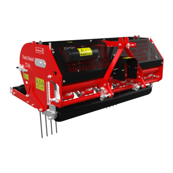
Verti-Drain®
Model 7316
Serial number:
Translation of the original operating instructions
IN ORDER TO ENSURE THE SAFE USE AND TO ACHIEVE THE BEST
PERFORMANCE, IT IS ESSENTIAL THAT THIS OPERATORS MANUAL
IS CAREFULLY READ BEFORE THE VERTI-DRAIN IS USED.
NOTE:
1735 English 911.120.441
Kwekerijweg 8
3709JA Zeist
The Netherlands
T: (31)306933227
F: (31)306933228
E:
verti-drain@redexim.com
www.redexim.com
Advertisement
Table of Contents

Related Manuals for Redexim Verti-Drain 7316


Summary of Contents for Redexim Verti-Drain 7316
- Page 1 Kwekerijweg 8 3709JA Zeist The Netherlands T: (31)306933227 Model 7316 F: (31)306933228 verti-drain@redexim.com Serial number: www.redexim.com Translation of the original operating instructions NOTE: IN ORDER TO ENSURE THE SAFE USE AND TO ACHIEVE THE BEST PERFORMANCE, IT IS ESSENTIAL THAT THIS OPERATORS MANUAL IS CAREFULLY READ BEFORE THE VERTI-DRAIN IS USED.
-
Page 2: Foreword
FOREWORD. Congratulations on the purchase of your VERTI-DRAIN. To ensure the safe and lasting operations of this VERTI-DRAIN you (and anyone using the machine) should read and understand this user's manual. A complete knowledge of the contents of the manual is necessary in order to ensure the safe use of this machine. -
Page 3: Safety Instruction
SAFETY INSTRUCTIONS Always use the VERTI-DRAIN with the correct tractor as described in the technical information The user is responsible for a safe Tractor/VERTI-DRAIN combination. The combination must be tested for noise, safety, risk and easy usage. It is also necessary to draw up user instructions. -
Page 4: Table Of Contents
CONTENTS. Par. Description Page Foreword Guarantee conditions Registration card Safety instruction Technical specification First set up Lifting machine from pallet General controls PTO length Use of PTO Slip clutch information and maintenance Working depth adjustment Tine angle adjustment Ground speed Starting procedures General usage of Verti-Drain 10.0... -
Page 5: Technical Specification
1.0 TECHNICAL SPECIFICATIONS. Model 7316 Working width 1.60 mtr (5’4”) Working depth Up to 300 mm (12”) Tractor speed @ 500 rev’s at PTO Hole spacing 65 mm (2-1/2”) Up to 0.85 km/h (0.55 mph) Hole spacing 130mm( 5”) Up to 1.75 km/h (1.10 mph) Hole spacing 195mm(7-1/2”) Up to 2.60 km/h (1.60 mph) PTO speed: (max) -
Page 6: First Set Up
Fig.1. 2.0 FIRST SETUP, LIFTING MACHINE FROM PALLET The machine stands vertically up on the pallet. To remove the pallet and get the machine horizontal on the ground, handle as follows (see fig.1 ): 1. Open the rear cover 2. Connect a cable to lift point * ensure the cable/crane/lift truck can lift minimum 2000 Kg.(5000 lbs). -
Page 7: General Controls
Fig.2. 3.0 GENERAL CONTROLS In fig.2. some key details of the machine are shown, as follows: 1. Safety decal RA, before using machine read manual. Decal is located at the toolbox with manuals and combi-tool. 2. Safety decal 911.280.402, Keep 4 mtr (14') distance to the machine + Turn engine off when maintaining or repairing machine * All decal should be on the machine and understood all the time 3. -
Page 8: Pto
4.0 PTO. The PTO is a very important item. It drives the machine from the tractor and ensures the safe operations when correctly maintained and installed. The PTO shaft has its own CE certification. Read the PTO shaft manual, which is connected to the shaft itself L standard = 33 mm 1.300"... -
Page 9: Use Of Pto
4.2 USE OF PTO For the correct use of the PTO, the following items need to be checked: 1. During work the angle of the joints may never exceed 30 degrees 2. The joints have to be in line all the time 3. -
Page 10: Working Depth Adjustment
Fig.4. Fig.5. 5.0 WORKING DEPTH ADJUSTMENT. The working depth can be adjusted when the machine is lifted from the ground as follows, see fig. 4: Unscrew nuts 1 at each side of the machine one turn. Screw spindle 3 in or out. Every revolution is 4 mm (0.160"). -
Page 11: Ground Speed
@ The angle of 90 degrees means that the tines penetrate perpendicular into the ground. This is only true if the machine is correctly set, see fig.1. If this isn't correct a push force F, see fig 5. is applied, which can seriously damage the machine. -
Page 12: Starting Procedures
Fig.7. 8.0 STARTING PROCEDURES The starting procedure is VERY important. If the start up is not done as described hereunder, serious damage to the machine may occur. Proceed as follows, see fig.7.: 1. Drive to the spot you want to start the operation. 2. -
Page 13: General Usage Of Verti-Drain
9.0 GENERAL USAGE OF VERTI-DRAIN The VERTI-DRAIN can only be used when the circumstances are right. Check the following items: 1. Are there any loose objects on the field. If so, these must be removed first. 2. Are there any slopes. The maximum slope for the VERTI-DRAIN is 20 degrees. Always operate the VERTI-DRAIN from the top to the bottom of a slop. -
Page 14: Problem Analysis
12.0 PROBLEM ANALYSIS Machine vibrates Crankshaft rotates irregular Machine not at 90 degrees PTO joint angles different PTO joints not in line Tough circumstances Adjust working depth Use thinner/ shorter tines If dry, irrigate first Solid/ hollow tines Wrong tine Change tine, use shorter one Are bending/ breaking Use solids first before hollow to... -
Page 15: Maintenance
Use 80W90 (5 liter). hours. gearbox. 14.0 EU-Declaration We, Redexim Utrechtseweg 127 3702 AC Zeist Holland, hereby declare fully on our authority that the product: VERTI-DRAIN 7316, WITH MACHINE NUMBER AS INDICATED ON THE MACHINE AND IN THIS MANUAL, to which this declaration relates is according to the stipulation of the 2006/42/EC directive for machines as well as the following standards: NEN-EN-ISO 12100 : 2010 and NEN-EN-ISO 13857 : 2008. -
Page 16: Technical Information
15.0 TECHNICAL INFORMATON Generally speaking, this Verti-Drain is not a complicated machine. A couple of technical items will be explained. If you still have questions, please contact your dealer, who is willing to assist you. 15. TORQUE SETTINGS. In fig. 8 the torque settings of the most important bolts/nuts are given. For the ones the torque setting is not mentioned, please be sure that they are tightened as a similar size bolt/nut would be tightened. -
Page 17: The Crankshaft
Fig.9. 15.2 THE CRANKSHAFT In fig.9. the assembly of the crankshaft is given. Also look at the spare part page for a more clear view and set up. On a 7516 the angle between the handles on the gearbox should be 60 degrees. 15.2.1 REPLACING THE TRANSMISSION OIL SEAL. -
Page 18: Replacing Of A Crank And Crank Bearing
15.2.2. REPLACEMENT OF A CRANK WITH BEARING Replacing a crank is necessary when it is cracked or when the big end nuts start to come loose on a regular base. Either the crank bearing, the crank bearing fitting or the big end pin holes in the crank are damaged. -
Page 19: Options, Wheel Kit
Fig.10. 16.0 OPTIONS, WHEEL KIT. The part number for a full transport kit for the 7316 is 9200100. This kit will be separately delivered and can be mounted to a standard 3-point linkage machine. Generally speaking, a machine with wheel kit will reduce the minimum horsepower required by 5 HP It also can be taken off quickly, so the machine can be used either way 16.0.1 MOUNTING THE WHEELKIT TO THE MACHINE On attached pages a detailed sketch is given from the assembly of the wheelkit of the 7316. -
Page 20: Some Guidelines For The Wheel Kit Use
hole at support AD. When the shaft is in place mount bolt S with washer R. Do not tighten the bolt. 6. Continue to do exactly the same at the other side of the machine. Since the wheel kit is symmetric, all parts are the same. -
Page 21: Options, Core Collector
Fig.11. 16.1 OPTIONS, CORE COLLECTOR. An easy mountable core collector is available for the 7316. The part number is 920080. ASSEMBLING INSTUCTIONS ( see Fig 11): Preparation of the Verti-Drain: Fit eye bolts 24 to the main frame 26 Assemble bushes 15 with the new longer bolts I to the rear roller supports. @ These bushes can stay on the machine all the time @ Use washers 16 to align the bushes to the rear roller scraper support. - Page 22 USER INSTRUCTIONS: When the core collector and the Verti-Drain are well prepared, the core collector supports 17 can be slided (X) onto the bushes 15. Secure it with R pins 19. The rear roller is of the ground, when the core collector is attached. It the clearance is not enough, do NOT remove the rear roller ( since the weight is needed) but turn the roller up by taking on bearing bolt out.
-
Page 23: Options, Turf Hold Down Kit
Fig.12. 16.2 OPTIONS, TURF HOLD DOWN KIT. (Old set till serial number A00127) A Turf Hold Down Kit can be used when the turf is coming loose. Two kits are available for the 7316. One with fingers lining up with the 12 mm ( ½”) holes of the tine holder ( part # 9200045) and one with finger lining up with the 18 mm (3/4”) holes (part # 9200047). -
Page 24: Options, Tines
16.3 OPTIONS, TINES Tines are essential for the correct working of the machine. Several tines are available for this machine, see the spare part pages for a total overview. Generally speaking, tines can be divided into two categories: Solids and Hollows. We advise using genuine tines, since they are fully adapted to the machine. -
Page 25: Hollow Tines
Shorter (worn) tines can be used in case shallower penetration is required. The machine doesn’t need to be adjusted that much at that time. Note that the depth reading on the decal is only correct when using the full maximum length tine If oval holes are created, it means that we have a weak top layer and a hard pan underneath. -
Page 26: Mini Needle Tines
Fig.14. 16.4.2. MINI NEEDLE TINES. Mini Needle (solid) tines need another adapter block. The two studs D ( fig 14, right) fit a 12 mm ( ½”) hole C of the standard machine tine head. Per adapter block we have 3 rows with each 8 holes. So per block we can mount 24 mini needle tines. If a full mounted block damages the turf, reduce the number of tines, like is shown in I, II and III.
Need help?
Do you have a question about the Verti-Drain 7316 and is the answer not in the manual?
Questions and answers