
Related Manuals for INHENERGY HI-3K-SL


Summary of Contents for INHENERGY HI-3K-SL
- Page 1 User Manual HI-3K-SL, HI-3.6K-SL, HI-4K-SL,HI-4.6K-SL, HI-5K-SL, HI-6K- V1.3 INHENERGY CO., LTD.
-
Page 2: Table Of Contents
CONTENTS 1 NOTES ON THIS MANUAL .................... - 3 - 1.1 Validity ........................- 3 - 1.2 Symbols in this document ..................- 3 - 2 OVERVIEW ........................- 5 - 2.1 Product Introduction ....................- 5 - 2.2 Appearance ........................ - 5 - 3 INSTALLATION ....................... - Page 3 User Manual 7.3 Check and Set the Standard for Grid Connection ............. - 27 - 7.4 Check and Set the Battery Type ................- 28 - 7.5 Check and Set the CT1 Type ................... - 29 - 7.6 Check and Set CT2 Type (Optional) ................. - 29 - 7.7 Check and Set Off-grid Parameters ................
-
Page 4: Notes On This Manual
The manual and other documents must be stored in a convenient place and be available at all times. We assume no liability for any damage caused by failure to observe these instructions. For changes in this manual, Inhenergy Co., Ltd. accepts no responsibilities to inform the users. - Page 5 User Manual CAUTION indicates a hazardous situation which, if not avoided, could result in minor or moderate injury. NOTICE is used to address practices not related to personal injury Information that you must read and know to ensure optimal operation of the system. Markings on this product Symbol Explanation...
-
Page 6: Overview
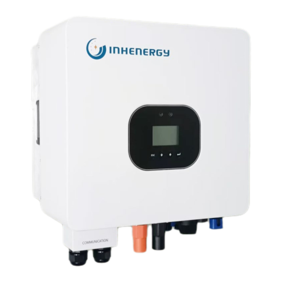
PV power is insufficient to meet self-consumption. If battery power is not sufficient, the system will take power from grid to support loads. Models This document involves the following product models: HI-3K-SL,HI-3.6K-SL,HI-4K-SL,HI-4.6K-SL,HI-5K-SL,HI-6K-SL. Model description (HI-6K-SL is used as an example) Model description Icon... - Page 7 User Manual ① LED indicator ② LCD display ③ Function button ④ Communication port ⑤ GPRS/WIFI output port ⑥ Battery Terminals(+) ⑦ Battery Terminals(-)⑧DC switch ⑨ Grid Port ⑩ DC input terminals (PV1) ⑪DC input terminals (PV2) ⑫ GEN Port ⑬...
-
Page 8: Installation
User Manual Up button: Move cursor to upside or increase value. OK button: Confirm the selection. 3 Installation 3.1 Check for Physical Damage Make sure the inverter is intact during transportation. If there is any visible damage, such as cracks, please contact your dealer immediately. 3.2 Packing List Open the package and take out the product, please check the accessories first. -
Page 9: Mounting
User Manual Bracket PV connectors (2*positive,2*negative) PV pin connectors (2*positive, 2*negative) User manual Expansion tubes Expansion screws Ring terminal Set screw (for mounting,external enclosure grounding) grid output connector Load/GEN connector Lead-acid battery temperature sensor Meter (optional) Wi-Fi module (optional) RJ45 connector * P: When the length of CT wire cannot meet the use requirements, the CT communication wire can be extended through RJ45 connector. -
Page 10: Space Requirement
User Manual ◆ The slope of the wall should be within 15°. 3.4 Space Requirement - 9 -... -
Page 11: Mounting Steps
User Manual 3.5 Mounting Steps 1.Use the wall bracket as a template to mark the position of the 3 holes on the wall(unit: mm). 2.Drill holes with driller, make sure the holes are deep enough (at least 60mm) for installation, and then tighten the expansion tubes. -
Page 12: Electrical Connection
User Manual 4 Electrical Connection ◆ For Australian safety country, the neutral cable of Grid side and Load side must be connected together, otherwise Load function will not work. System connection diagrams - 11 -... -
Page 13: Pv Connection
User Manual 4.1 PV connection ◆ Conditions for DC Connection The inverter has 2 independent inputs: PV1 & PV2 Notice that the connectors are in paired (male and female connectors). The connectors for PV arrays and inverters are H4 connectors. - 12 -... - Page 14 User Manual The solar modules connected to the inverter must conform to the Class A requirements of the IEC 61730 standard. If the inverter is not equipped with a DC switch but this is mandatory in the country of installation, install an external DC switch. The following limit values at the DC input of the inverter must not be exceeded: Model...
-
Page 15: Battery Connection
User Manual Plug the PV connector into the corresponding PV connector on inverter. 4.2 Battery Connection ◆ Lead-Acid and other similar older-technology battery types require experienced and precise design, installation, and maintenance to work effectively. For lead-acid battery bank, the inconformity between battery cells might lead to battery cell over-charge or discharge, and further might damage battery cells and shorten battery bank life. - Page 16 User Manual 4. Tighten the screw cap. 4.3 Grid & GEN & Backup Connection An external AC switch is needed for grid connection to isolate from grid when necessary. ◆ Make sure inverter is totally isolated from any DC or AC power before connecting AC cable.
- Page 17 User Manual Load Connection Diameter 10-14mm Area 6mm²or 10AWG Length 10mm - 16 -...
-
Page 18: Earth Connection
User Manual GEN Connection Diameter 10-14mm Area 6mm²or 10AWG Length 10mm 4.4 Earth Connection Users must additionally earth the inverter to the enclosure of a second earthing or equipotential bonding. This prevents electric shock if the original protective conductor fails. Earth Connection Steps: 1. -
Page 19: Communication Connection
User Manual 4.5 Communication Connection 1.Function port definition Object Category Description RS485/CAN/NTC port for battery communication DRMS For Australia market only Current transformer port1/ Meter communication port Reserve PARA1 Reserve PARA2 Reserve Upgrade firmware program port External devices communication port DIP Switch - 18 -... - Page 20 User Manual Make sure use standard RJ45 cable and plug, as below ◆ DRMS RS485B CT1_RS485B DRM1/5 RS485A CT1_N DRM2/6 GND-S CT1_N DRM3/7 CANH GND-S DRM4/8 CANL CT1_RS485A DRM_REF NTC.BAT CT1_P DRM_COM Wake- CT1_P RS485A Wake+ CT1_ON+ RS485B 2.CT1 Connection ◆...
- Page 21 User Manual Connection Steps: 1.Uninstall the “CT” cable from the accessory bag. 2.Thread the “CT” cable through the cable gland. 3.Insert the RJ45 plug of the network cable into the “CT1” pin connector on the inverter until it snaps into place. the completed appearance is like the below figure. 2.Meter Connection (optional) ◆...
- Page 22 User Manual Description CT1-Pin Meter-Pin CT1_RS485B CT1_RS485A 4.BMS Connection ◆ Using CAN or RS485 communication with lithium batteries. - 21 -...
- Page 23 User Manual ◆ Using lead-acid batteries, a temperature sensor must be connected. ◆If you are using a lead-acid battery, you do not need to install CAN or RS485 communication. ◆The CAN battery communication and RS485 battery communication can't be installed at same time. Connection Steps: 1.Prepare communication cable.
-
Page 24: Powering On The System
User Manual 5 Powering On the System Before turning on the AC switch between the inverter and the power grid, use a multimeter set to the AC position to check that the AC voltage is within the specified range. 5.1 Start-Up the inverter 1.Turn on the DC switch between the battery and the inverter. -
Page 25: Lcd Operation
User Manual Do not disconnect the DC connectors under load. Turn-off the inverter step: 1. Press and hold the "Enter" button for 3S to enter the shutdown interface and select "OFF". 2. Turn off the AC switch between the inverter and the power grid. 3. - Page 26 User Manual System Status System Status Battery Volt / Battery SOC System Time BAT:xx.xV/xxx% 20XX/XX/XX/XX:XX System Status Battery Power Serial Number Pbat: (+/-)XXXX W xxxxxxxxxxxxxxxx System Status System Status PV1 Volt / PV2 Volt System Model Vpv:xx.xV/xx.xV Model:xxxxxxxxxx System Status System Status PV1 Power / PV2 Power Firmware Version...
- Page 27 User Manual System Status System :ON/OFF System Status Charge Set System Status PeakLoadShifting System Status DisCharge Set System Status DisChargeLimit System Status SelfConsumption System Status Prevent BackFlow System Status Backup: Disable System Status System Status AC Volt: 230 V Back-up 240 V 208 V System Status...
-
Page 28: Enter Setting Interface
User Manual When the inverter is operating normally, the current flows between the modules, indicated by ●, with the following details: Blinking ●: Standby connection, no actual energy transfer. Flow ●●●: Normal energy flow transmission. The flow direction of "●" is the current flow direction. -
Page 29: Check And Set The Battery Type
User Manual check or select the required grid standard. User need to long press "Enter" button for 5 seconds and then release it to enter the password verification screen to access "Development" interface. For example, if the grid connection standard is set to "CEI021", inverter will provide automatic self-test function. -
Page 30: Check And Set The Ct1 Type
User Manual CV: Default 58.0V, Range 55.0~59.2V, Constant voltage of lead-acid battery. LV: Default 47V, Range 44~50V, Lead Acid Battery Stop Discharge Voltage Before wiring, please pay attention that neither battery power line positive or negative cannot be reversed in the inverter battery port! 7.5 Check and Set the CT1 Type System Status System Status... -
Page 31: Inverter Used Under Peakloadshifting Mode
User Manual If the user needs to use the Back-up function when there is no utility power, the back-up function should be turned on. Check and set the corresponding Back-up output voltage and frequency. Back-Up: Disable, off-grid function is not enabled. No output from the backup port when grid outage. - Page 32 User Manual System Status Time1 System Status Time2 System Status Time3 System Status System Status Charge Set PeakLoadShifting System Status Stop SOC: 100% System Status Power Rate: 100 % System Status PVchargeOnly:ON/OFF When the utility charging cost is low or the battery SOC is low, user need to force the battery to be charged.
- Page 33 User Manual according to the set discharge power (rated battery power*Power Rate) and stop discharging when the discharge SOC reaches "Stop SOC". "Forced Charge or Forced Discharge Set" is provided with three separate time periods for setting. Users can force charge and force discharge the battery multiple times in one day, just make sure the force charge and force discharge times do not conflict.
-
Page 34: Inverter Used Under Self-Consumption Mode
User Manual and the extra solar energy will charge the battery instead of battery discharge. PeakLoadShifting Mode. When Grid, Battery is available (without PV) During charge time, Grid will charge battery and supply power to the loads at the same time no matter PVchargeOnly is On or Off. - Page 35 User Manual can access the "Discharge Limit" screen in "SelfConsumption" by pressing the "↑" or "↓" and "Enter" buttons, set and enable the limit battery discharge time. During this set time period, the battery is not discharged, and the load is powered directly from the utility. The "self-consumption" mode also supports three settable time periods to limit battery discharge.
-
Page 36: Restore Default Factory Settings
User Manual limit time, the battery can only charge and no discharge. Self-consumption mode. When Grid is available, without PV or Battery. When Pload>0, the loads is going to use Grid power, battery will discharge to reduce Grid consume power. If Pload>Pbat, Grid will supply for loads with battery. -
Page 37: Trouble Shooting
User Manual 3. Checking the DC switch Check for externally visible damage and discoloration of the DC switch and the cables at regular intervals. If there is any visible damage to the DC switch, or visible discoloration or damage to the cables, contact the installer. - Page 38 User Manual Check the frequency is in the range of specification or not. AC Freq Out Restart inverter. Please contact the manufacturer if restart can't solve the problem. Check the positive and negative of battery is reversed or not. Reversed Check the battery connection is good or not.
-
Page 39: Decommissioning
User Manual DSP RX Restart inverter. Please contact the manufacturer if restart can't solve Fault! the problem. BackUp Check the load of BackUp. Short! Check the output of UPS. Especial not connect to grid Restart inverter. Please contact the manufacturer if restart can't solve AuotTest Err! the problem. -
Page 40: Storage And Transportation
User Manual ◆ If the original package is no longer available, you can also use an equivalent carton that meets the following requirements. 9.3 Storage and Transportation ◆ Store the inverter in a dry environment where ambient temperature is always between - 20 °C - +60 °C. - Page 41 User Manual Start voltage/Minimum 100V/80V working voltage Number independent trackers / strings per MPP tracker Max. input current of 15A/15A tracker A/ tracker B AC Output Data ( Gird ): Rated output 3.6KW 4.6KW power Max. AC apparent 4.6KW / 3.3KVA 4KVA 4.4KVA...
- Page 42 User Manual Rated output 3KVA 3.6KVA 4KVA 4.6KVA 5KVA 6KVA power Rated output 230V ±20% voltage Rated output 50/60±0.2% frequency THDV@Rated Linear <3% load Transfer Time <10ms Battery data : Battery Type Lithium /Lead-acid Nominal voltage Battery voltage range 42V-59V Max charging current 100A 100A...
-
Page 43: Appendix
Installation style Wall mounted Self-Consumption <3W Inverter Topology Transformerless Display LCD and App Interfaces Wi-Fi/GPRS Warranty 5 years 11 Appendix Approved battery brand from Inhenergy. Brand RS485 or CAN JOHNRAY PYLON RS485 PYLON 3.0 RS485 DYNESS RS485 RS485 GenixGreen RS485... -
Page 44: Manufacturer's Warranty
2. Modules information 3. Communication method 4. Serial number of Inverters 5. Error code of Inverters 6. Display of inverter LCD INHENERGY CO., LTD. ADD: INHE Smart Power Distribution Industrial Base, Hi-tech Zone, Zhuhai, China. P.C.: 519000 Tel: +86-756-368-9696 Web: www.inhenergy.com Email: info@inhenergy.com...
Need help?
Do you have a question about the HI-3K-SL and is the answer not in the manual?
Questions and answers
i need a manual please