
Related Manuals for INHENERGY SI-3.6K-S2


Summary of Contents for INHENERGY SI-3.6K-S2
- Page 1 User Manual SI-3.6K-S2, SI-4K-S2, SI-4.6K-S2, SI-5K-S2, SI-6K-S2 INHENERGY CO., LTD.
-
Page 2: Table Of Contents
CONTENTS 1 NOTES ON THIS MANUAL......................- 3 - 1.1 VALIDITY........................... - 3 - 1.2 SYMBOLS IN THIS DOCUMENT..................- 3 - 2 OVERVIEW............................- 5 - 2.1 PRODUCT INTRODUCTION....................- 5 - 2.2 APPEARANCE..........................- 5 - 3 INSTALLATION..........................- 6 - 3.1 CHECK FOR PHYSICAL DAMAGE..................- 6 - 3.2 PACKING LIST..........................- 6 - 3.3 MOUNTING.......................... - Page 3 User Manual 8 DECOMMISSIONING........................- 17 - 8.1 REMOVE THE INVERTER....................- 17 - 8.2 PACKAGING........................... - 17 - 8.3 STORAGE AND TRANSPORTATION.................- 17 - 9 TECHNICAL DATA........................- 18 - 10 MANUFACTURER WARRANTY....................- 19 - 11 CONTACT.............................- 19 - - 2 -...
-
Page 4: Notes On This Manual
Additional information Find further information on special topics in the download area at www.inhenergy.com The manual and other documents must be stored in a convenient place and be available at all times. We assume no liability for any damage caused by failure to observe these instructions. - Page 5 User Manual NOTICE is used to address practices not related to personal injury Information that you must read and know to ensure optimal operation of the system. Markings on this product Symbol Explanation Caution,risk of electric shock Caution,hot surface Operation after 5 minutes Read the manual Point of connection for grounding protection CE mark.
-
Page 6: Overview
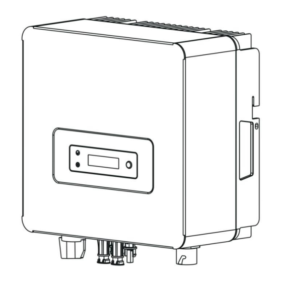
The Inverters is a single-phase grid-tied PV string inverter that converts the DC power generated by PV strings into AC power and feeds the power into the power grid. Models This document involves the following product models: SI-3.6K-S2,SI-4K-S2,SI-4.6K-S2,SI-5K-S2,SI-6K-S; Model description (SI-6K-S2 is used as an example) Model description Icon... -
Page 7: Installation
User Manual LED indicator description Category Status Meaning Blinking green at short intervals waiting status Blinking green at long intervals Self-check Steady green normal status Blinking red at short intervals Alarm Steady red Fault faultless Function button description Status Description Down:Move cursor to downside or decrease value Short press (0.5s) Enter:Confirm the selection. -
Page 8: Mounting
User Manual Object Description Quantity Inverter Bracket AC connector PV connectors (2*positive, 2*negative) PV pin connectors (2*positive, 2*negative) Expansion tubes/Set screw Set screw( for mounting) User manual Wifi/GPRS module (optional) CT connectors (optional) 3.3 Mounting Installation Precaution SI-6-S2 Series inverter is designed for outdoor installation (IP 65). Make sure the installation site meets the following conditions: ◆... - Page 9 User Manual 1.Solid brick/concrete, or strength equivalent mounting surface; 2.Inverter must be supported or strengthened if the wall’s strength isn’t enough(such as wooden wall, the wall covered by thick layer of decoration). Please avoide direct sunlight, rain exposure, snow laying up during. ◆...
-
Page 10: Space Requirement
User Manual 3.4 Space Requirement 3.5 Mounting Steps 1.Use the wall bracket as a template to mark the position of the 3 holes on the wall. 2.Drill holes with driller, make sure the holes are deep enough (at least 60mm) for installation, and then tighten the expansion tubes. -
Page 11: Electrical Connection
User Manual 4 Electrical Connection 4.1Grid Connection SI-6K-S2 Series inverter are designed for single phase grid. Voltage is 220/230/240V, frequency is 50/60Hz. Other technical requests should comply with the requirement of the local public grid.Micro-breaker should be installed between inverter and grid, any load should not be connected with inverter directly. - Page 12 User Manual Connection Steps 1. Choose the appropriate wire(Cable size: refer to Table3). 2.Remove 10mm of insulation from the end of wire. 3.Thread cables through pressure screw, seal ring, threaded sleeve in sequence. 4. insert the stripped and bared conductors L,N,PE into the screw terminals with sign L , N ,PE on the socket element and tighten the screws firmly.
-
Page 13: Earth Connection
User Manual 4.2 Earth Connection Users must addtionally earth the inverter to the enclosure of a second earthing or equipotential bonding. This prevents electric shock if the original protective conductor fails. Earth Connection Steps: 1. Strip the earthing cable insulation and insert the stripped cable into the ring terminal, then clamp it . -
Page 14: W I F I /Gprs Connection
User Manual Danger to life due to lethal voltages! ◆ PV array supplies d.c voltage to inverter when exposed to light,before connecting the PV array, cover some light screens above PV arrays,ensure that the DC switch and AC breaker are disconnect from the inverter. -
Page 15: Turn-Off The Inverter
User Manual 4.4 Turn-off the Inverter Do not disconnect the DC connectors under load. Turn-off the inverter step: 1.Disconect the line circuit breaker from single-phases grid and prevent it from being reactivated. 2.Turn off the dc switch. 3.Check the inverter operating status. 4.Waiting until LED, OLED have go out, the inverter is shut down. -
Page 16: Lcd Operation
User Manual 6 LCD Operation The main interface is the default interface, the inverter will automatically jump to this interface when the system started up successfully or not operated for a period of time. Menu interface - 15 -... -
Page 17: Maintenance And Cleaning
User Manual 7 Maintenance and Cleaning 7.1 Maintain Periodically 1.Checking Heat Dissipation If the inverter regularly reduces its output power due to high temperature, please improve the heat dissipation condition. Maybe you need to clean the heat sink. 2. Cleaning the Inverter If the inverter is dirty, turn-off the AC breaker and DC switch ,waiting the inverter shut down ,then clean the enclosure lid, the display, and the LEDs using only a wet cloth. -
Page 18: Decommissioning
User Manual Amb Temp Over disappear, contact DSP Comm Faul the manufacturer Sink Temp Over Login Fault Replace the AC Relay Fault Clock Warn internal button pool Normal Reserved Power is zero shutdown at low power 8 Decommissioning 8.1 Remove the Inverter ◆... -
Page 19: Technical Data
User Manual 9 Technical Data Model SI -3.6K-S2 SI-4K-S2 SI-4.6K-S2 SI -5K-S2 SI-6K-S2 Input Data Max. DC input power 4700W 5500W 6000W 6500W 7800W Max. DC input voltage 550V Operation voltage range 80V-540V Number of independent 2/1+1 MPPT/strings per MPPT MPPT max. -
Page 20: Manufacturer Warranty
User Manual Weight <10kg Operation temperature –25 °C ... +60 °C range Noise ≤25dB Heat dissipation mode Natural IP Class IP65 Features LCD display Communication WiFi/GPRS/RS485 interface 10 Manufacturer Warranty Please refer to the warranty card 11 Contact If you have technical problems concerning our products, contact your installer or manufacturer. - Page 21 User Manual INHENERGY CO., LTD. ADD: 6/F, Building No.4,No.1, Keji 7th Rd, Xiangzhou District, Zhuhai, Guangdong,China. P.C.: 519000 Tel: +86-756-368-9696 Web: www.inhenergy.com Email: info@inhenergy.com - 20 -...
Need help?
Do you have a question about the SI-3.6K-S2 and is the answer not in the manual?
Questions and answers